CPU Unit Specifications - OMRON Russia ...
CPU Unit Specifications - OMRON Russia ...
CPU Unit Specifications - OMRON Russia ...

Create successful ePaper yourself
Turn your PDF publications into a flip-book with our unique Google optimized e-Paper software.
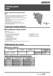
A Wide Range of <strong>CPU</strong> <strong>Unit</strong>s Allows You to Select the Ideal Model.CP-series LineupProgram capacityProcessing speedA program capacity of 20K steps and 0.1 µs high-speed processing providemulti-axis, high-speed positioning control or analog control. CJ-series SpecialI/O <strong>Unit</strong>s and <strong>CPU</strong> Bus <strong>Unit</strong>s can also be used.CP1H SeriesPulse OutputsFour-axis control is a standard feature.CountersFour-axis differential-phase control isa standard feature.Program capacity20K stepsProcessing speed0.1 µs(basic instructions)A Choice of Three Types of CP1H <strong>CPU</strong> <strong>Unit</strong> Lets You Select the Functions You Need.Pulse Outputsfor 4 AxesHigh-speedCounters for4 AxesHigh-speed PositioningCP1H-Y <strong>CPU</strong> <strong>Unit</strong>sTwo axes at 1 MHz and two axes at 100 kHzTwo axes at 1 MHz for single-phase (500 kHz fordifferential phases) and two axes at 100 kHz forsingle-phase (50 kHz for differential phases)Built-in Analog I/OCP1H-XA <strong>CPU</strong> <strong>Unit</strong>sFour axes at 100 kHzStandard TypeCP1H-X <strong>CPU</strong> <strong>Unit</strong>sFour axes at 100 kHz for single-phase(50 kHz for differential phases)150 mmCP1H- 40D -90 mm85 mmUSB Peripheral PortAnother standard feature.Serial CommunicationsTwo ports. Select Option Boards for either RS-232C orRS-485 communications.LCD Displays and SettingsEnabled using Option Board.Built-in Analog I/OXA <strong>CPU</strong> <strong>Unit</strong>s provide 4 input words and 2 output words.Built-inAnalog I/OFour analog inputs andtwo analog outputsSerialCommunicationsRS-232COption BoardRS-422A/485Option BoardUp to two Option Boards can be mounted.Program capacity10K stepsProcessing speed0.55 µs(basic instructions)LCD DisplaySettingsLCDOption BoardOne LCD Option Board can be mounted in option board slot 1.Basic package PLCs with serious functions from simple sequence controlto 2-axis positioning control.CP1L Series130 mmCP1L-M30D -90 mm85 mm90 mm85 mm150mm195 mmCP1L-M40D - CP1L-M60D -90 mm85 mmProgram capacity5K stepsProcessing speed0.55 µs(basic instructions)90 mm85 mm66 mmCP1L-L10D -90 mm85 mm90 mm85 mm86 mm86 mmCP1L-L14D - CP1L-L20D -Pulse OutputsTwo-axis control at 100 kHz isa standard feature.Counters with 2-axis differentialphasecontrol are standard features.Single-phase: 4 axes at 100 kHzUSB Peripheral PortAnother standard feature.Serial CommunicationsTwo ports (See note.). Select Option Boards for either RS-232C orRS-485 communications.Note: CP1L-L <strong>CPU</strong> <strong>Unit</strong>s with 14 and 20 points support only one port.Cannot be used for the CP1L-L10.LCD Displays and SettingsEnabled using Option Board. (See note.)Note: Cannot be used for the CP1L-L10.10 points 14 points 20 points30 points 40 points 60 pointsI/O capacity45
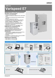
Expansion <strong>Unit</strong>s Provide for a Wider Range of Applications.ExpandabilityApplicationsUsing Only CP1W <strong>Unit</strong>s with the CP1HCP1L-M30D - /CP1L-M40D - /CP1L-M60D -Up to three CP1W/CPM1A Expansion <strong>Unit</strong>sand Expansion I/O <strong>Unit</strong>s can be connected.Up to 7 CP1W/CPM1A Expansion <strong>Unit</strong>s and Expansion I/O <strong>Unit</strong>s can be connected.Note: Some Expansion <strong>Unit</strong>s and Expansion I/O <strong>Unit</strong>s have certain restrictions on use.(For details, refer to page 24.)CP1L-L14D - /CP1L-L20D -Note: Cannot be used for the CP1L-L10.Using CJ-series Special I/O <strong>Unit</strong>s, CJ-series <strong>CPU</strong> Bus <strong>Unit</strong>s, and CP1W <strong>Unit</strong>s with the CP1HOne CP1W/CPM1A Expansion <strong>Unit</strong> or Expansion I/O <strong>Unit</strong> can be connected.Up to two CJ-series <strong>CPU</strong> Bus <strong>Unit</strong>s or Special I/O <strong>Unit</strong>s canbe connected.CP1H/CP1L Communications Interface OptionsCJ <strong>Unit</strong> AdaptorCP1W-EXT01Two Optional Serial PortsOption BoardsUp to 7 CP1W/CPM1A Expansion <strong>Unit</strong>s and Expansion I/O <strong>Unit</strong>s can be connected.CP1W/CPM1A Expansion <strong>Unit</strong>s and Expansion I/O <strong>Unit</strong>s and CJ <strong>Unit</strong>s can be used simultaneously.CP1W-CN811 I/O Connecting Cable is required.Standard Feature:USB peripheral portCP1H/CP1LUp to two communications interface Option Boards(RS-232C or RS-422A/485) can be connected to theCP1H or CP1L <strong>CPU</strong> <strong>Unit</strong>s.RS-232C InterfaceCP1W-ClF01RS-422A/485 InterfaceCP1W-ClF11Two types of communications are available.Either two RS-232C ports or twoRS-422A/485 ports can be used.Note: Only one is supported by CP1L-L <strong>CPU</strong> <strong>Unit</strong>s (14or 20 points).Cannot be used for the CP1L-L10.CP1H Application ExamplesCP1L Application ExamplesBuilt-in Analog I/O:4 Analog Inputs and 2 Analog OutputsFour-axis, 1-MHz High-speedPulse Outputs4-axis, 1-MHz High-speed CountersTwo-axis Pulse Outputs Sequence Control Sequence Control with Clock FunctionForming MachineCP1H-XA <strong>CPU</strong> <strong>Unit</strong>Temperature Sensor <strong>Unit</strong>Electronic Parts AssemblyMachineCapacitor pickingSpinning Machine Packing Machine Air Cleaner Control Shopping Mall Fountain ControlHigh-speed countersProcessdepthProcesspositioningThread winding speedand length control4 analog inputs and2 analog outputsHydraulic pressure controlCP1H-Y <strong>CPU</strong> <strong>Unit</strong>Rotation(final positioning)CP1H-Y <strong>CPU</strong> <strong>Unit</strong>CP1LPulseoutputsPositioning controlvia ServomotorsPulseoutputsSheet feedingcontrol viaServomotorsCP1LAnalog Output <strong>Unit</strong>Cleaner fan motor control(Inverter)CP1L67
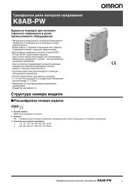
Maximize Efficiency by Selecting the Optimum <strong>CPU</strong> <strong>Unit</strong> for Your Applications.<strong>CPU</strong> <strong>Unit</strong>sCP1HY <strong>CPU</strong> <strong>Unit</strong>s XA <strong>CPU</strong> <strong>Unit</strong>s X <strong>CPU</strong> <strong>Unit</strong>s M Type 60 PointsCP1LM Type 40 Points M Type 30 Points L Type 20 Points L Type 14 Points L Type 10 PointsCP1H-Y20DT-DDC power supply, 12 DC inputs,8 transistor (sinking) outputsTwo line-driver inputsTwo line-driver outputsCP1H-XA40DR-AAC power supply, 24 DC inputs,16 relay outputs, 4 analog inputs,2 analog outputsCP1H-XA40DT-DDC power supply, 24 DC inputs,16 transistor (sinking) outputs,4 analog inputs, 2 analog outputsCP1H-XA40DT1-DDC power supply, 24 DC inputs,16 transistor (sourcing) outputs,4 analog inputs, 2 analog outputsCP1H-X40DR-AAC power supply, 24 DC inputs,16 relay outputsCP1H-X40DT-DDC power supply, 24 DC inputs,16 transistor (sinking) outputsCP1H-X40DT1-DDC power supply, 24 DC inputs,16 transistor (sourcing) outputsCP1L-M60DR-AAC power supply,36 DC inputs, 24 relay outputsCP1L-M60DT-AAC power supply, 36 DC inputs,24 transistor (sinking) outputsCP1L-M60DR-DDC power supply,36 DC inputs, 24 relay outputsCP1L-M60DT-DDC power supply, 36 DC inputs,24 transistor (sinking) outputsCP1L-M60DT1-DDC power supply, 36 DC inputs,24 transistor (sourcing) outputsCP1L-M40DR-AAC power supply, 24 DC inputs,16 relay outputsCP1L-M40DT-AAC power supply, 24 DC inputs,16 transistor (sinking) outputsCP1L-M40DR-DDC power supply, 24 DC inputs,16 relay outputsCP1L-M40DT-DDC power supply, 24 DC inputs,16 transistor (sinking) outputsCP1L-M40DT1-DDC power supply, 24 DC inputs,16 transistor (sourcing) outputsCP1L-M30DR-ADC power supply, 18 DC inputs,12 relay outputsCP1L-M30DT-AAC power supply, 18 DC inputs,12 transistor (sinking) outputsCP1L-M30DR-DDC power supply, 18 DC inputs,12 relay outputsCP1L-M30DT-DDC power supply, 18 DC inputs,12 transistor (sinking) outputsCP1L-M30DT1-DDC power supply, 18 DC inputs,12 transistor (sourcing) outputsCP1L-L20DR-AAC power supply, 12 DC inputs,8 relay outputsCP1L-L20DT-AAC power supply, 12 DC inputs,8 transistor (sinking) outputsCP1L-L20DR-DDC power supply, 12 DC inputs,8 relay outputsCP1L-L20DT-DDC power supply, 12 DC inputs,8 transistor (sinking) outputsCP1L-L20DT1-DDC power supply, 12 DC inputs,8 transistor (sourcing) outputsCP1L-L14DR-AAC power supply, 8 DC inputs,6 relay outputsCP1L-L14DT-AAC power supply, 8 DC inputs,6 transistor (sinking) outputsCP1L-L10DR-AAC power supply,6 DC inputs, 4 relay outputsCP1L-L10DT-AAC power supply, 6 DC inputs,4 transistor (sinking) outputsAvailable soon Available soon Available soon Available soon Available soon Available soonCP1L-L14DR-DDC power supply, 8 DC inputs,6 relay outputsCP1L-L14DT-DDC power supply, 8 DC inputs,6 transistor (sinking) outputsCP1L-L14DT1-DDC power supply, 8 DC inputs,6 transistor (sourcing) outputsCP1L-L10DR-DDC power supply,6 DC inputs, 4 relay outputsCP1L-L10DT-DDC power supply, 6 DC inputs,4 transistor (sinking) outputsCP1L-L10DT1-DDC power supply, 6 DC inputs,4 transistor (sourcing) outputsPulse outputs(only for transistor outputs)1 MHz for two axes(line driver outputs),100 kHz for two axes(four axes total)100 KHz for four axes100 kHz for two axesCountersSerialcommunications1 MHz (single-phase), 500 kHz(differential phases) for two axes(line driver outputs), 100 kHz (singlephase),50 kHz (differential phases)for two axes (four axes total)100 kHz (single-phase), 50 kHz (differential phases)Two serial ports can be added as options(either RS-232C or RS-422A/485 Option Boards).100 kHz (single-phase) for four axes, or 50 kHZ (differential phases) for two axesTwo optional serial ports can be added(either RS-232C or RS-422A/485 Option Boards).One optional serial port can be added(either an RS-232C or RS-422A/485 Option Board).USBperipheral portYesYesYesYesYesYesYesYesYesBuilt-in analog I/O4 analog inputs and2 analog outputs(resolution: 6,000 or 12,000)Memory CassetteYesYesYesYesYesYesYesYesYesLCDLCD display settingsAn LCD Option Board can be added as an option to option board slot 1.An LCD Option Board can be added asan option to option board slot 1.An LCD Option Board can be added asan option to option board slot 1.Function blocks(ladder diagrams orST language)YesYesYesYesYesYesYesYesYesInverter positioningYesYesYesYesYesYes7-segment displayYesYesYesProgram capacity20K steps10K steps5K stepsData memorycapacity32K words32K words10K wordsHigh-speedprocessing0.1 µs/LD instruction, 0.3 µs/MOV instruction0.55 µs/LD instruction, 1.84 µs/MOV instruction89
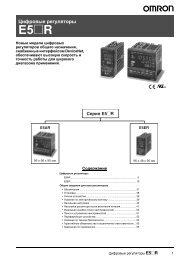
CP1W-series and CJ-series <strong>Unit</strong>s Can Be Use d for Maximum ExpandabilityExpansion <strong>Unit</strong>sOption BoardsOptionsTemperature Sensor <strong>Unit</strong>CompoBus/S I/OLink <strong>Unit</strong>RS-232COption BoardCP1W-ClF01CP1H and CP1LExpansion I/O <strong>Unit</strong>sRS-422A/485Option BoardCP1W-ClF11LCD Option BoardCP1W-DAM01Analog <strong>Unit</strong>sMemory CassetteCP1W-ME05MTemperature Sensor <strong>Unit</strong>CP1W-TS001TemperatureThermocouple inputs: 2•CP1W-TS002Thermocouple inputs: 4•I/O ConnectingCableCP1W-CN811 I/O Connecting Cable: 80 cmNote: CP1W/CPM1A Expansion <strong>Unit</strong>s include I/OConnection Cables (in lengths of approx. 6 cm) forside-by-side connection.Sensor <strong>Unit</strong>CP1W-TS101Platinum-resistance thermometer inputs: 2•CP1W-TS102Platinum-resistance thermometer inputs: 4•CPM1ACPM1AExpansion<strong>Unit</strong> andExpansionI/O <strong>Unit</strong>sCompoBus/S I/O Link <strong>Unit</strong>CP1W-SRT21• Inputs: 8• Outputs: 8Expansion <strong>Unit</strong> andExpansion I/O <strong>Unit</strong>s can beused with CP1H or CP1L <strong>CPU</strong><strong>Unit</strong>s under the sameconditions as for the CP1W.CP1W-8ED• 8 DC inputsCP1W-16ER• 16 relay outputsCP1W-20EDTCP1W-8ERCP1W-16ET• 8 relay outputsCP1W-8ETCP1W-16ET1• 8 transistor outputs(sinking)CP1W-8ET1• 8 Transistor outputs(sourcing)CP1W-32ER Available soon• 32 relay outputsCP1W-32ET Available soon• 32 transistor outputs (sinking)CP1W-32ET1 Available soon• 32 transistor outputs (sourcing)• 16 transistor outputs(sinking)• 16 transistor outputs(sourcing)CP1W-40EDR• 24 DC inputs• 16 relay outputsCP1W-40EDTCP1W-20EDR1• 12 DC inputs• 8 relay outputs• 12 DC inputs• 8 transistor outputs(sinking)CP1W-20EDT1• 12 DC inputs• 8 transistor outputs(sourcing)• 24 DC inputs• 16 transistor outputs (sinking)CP1W-40EDT1• 24 DC inputs• 16 transistor outputs (sourcing)Analog Input <strong>Unit</strong>CP1W-AD041• Analog inputs: 4 (resolution: 6,000)Analog Output <strong>Unit</strong>CP1W-DA041• Analog outputs: 4 (resolution: 6,000)Analog I/O <strong>Unit</strong>CP1W-MAD11• Analog inputs: 2 (resolution: 6,000)• Analog outputs: 1 (resolution: 6,000)AnalogCP1H OnlyCJ-series Special I/O <strong>Unit</strong>s and <strong>CPU</strong> Bus <strong>Unit</strong>sUp to two CJ-series Special I/O <strong>Unit</strong>s or <strong>CPU</strong> Bus <strong>Unit</strong>s can be connected by using a CJ <strong>Unit</strong> Adaptor.(Refer to page 25 for the <strong>Unit</strong>s that can be used. For details on CJ-series <strong>Unit</strong>s, refer to the CJ Series Catalog (Cat. No. P052).CJ <strong>Unit</strong> AdaptorCP1W-EXT01(with End Cover)<strong>CPU</strong> Bus <strong>Unit</strong>sInput <strong>Unit</strong>sCJ1W-ADG41(4 points)Special I/O <strong>Unit</strong>sAnalog Input <strong>Unit</strong>sCJ1W-AD041-V1CJ1W-AD081-V1(4 or 8 points)Position Control <strong>Unit</strong>sCJ1W-NC(1 to 4 axes)Position Control <strong>Unit</strong> withMECHATROLINK-IICommunicationsCJ1W-NCF71Analog Output <strong>Unit</strong>sCJ1W-DA021/041CJ1W-DA08V/08C(2, 4, or 8 points)High-speed Counter <strong>Unit</strong>CJ1W-CT021(2 axes)Motion Control <strong>Unit</strong> withMECHATROLINK-IICommunicationsCJ1W-MCH71Analog I/O <strong>Unit</strong>CJ1W-MAD42(4 analog inputs,2 analog outputs)ID Sensor <strong>Unit</strong>sCJ1W-V680C1CJ1W-V600C1(1 or 2 Heads)SYSMAC SPUHigh-speed DataCollection <strong>Unit</strong>CJ1W-SPU01-V2Process Input <strong>Unit</strong>sCJ1W-PH41UCJ1W-AD04UCJ1W-PTS51/52CJ1W-PTS15/16CJ1W-PDC15CompoBus/SMaster <strong>Unit</strong>CJ1W-SRM21Ethernet <strong>Unit</strong>CJ1W-ETN21(100Base-TX)Temperature Control<strong>Unit</strong>sCJ1W-TC(4 or 2 loops)CompoNet Master <strong>Unit</strong>CJ1W-CRM21Serial Communications<strong>Unit</strong>sCJ1W-SCU41-V1(RS-232C and RS-422/485ports)CJ1W-SCU21-V1(Two RS-232C ports)CJ1W-SCU31-V1(Two RS-422/485 ports)Controller Link <strong>Unit</strong>CJ1W-CLK23FL-Net <strong>Unit</strong>CJ1W-FLN22(100Base-TX)DeviceNet <strong>Unit</strong>CJ1W-DRM2110 11
Pulse OutputsUp to Four Axes Are Standard.Advanced Power for High-precision Positioning Control.Positioning for Electronic ComponentManufacturing EquipmentSheet Feeding for Vertical Pillow PackerPulse OutputsCP1HPulse Output Function for Up to Four Axes.Along with greater precision and more flexibility in multiproductmanufacturing, high-speed multi-axis pulse outputcontrol responds to the increase in servo applications.Programming Is Made Easy Using <strong>OMRON</strong> Function BlocksNote: For a list of function blocks in the <strong>OMRON</strong> Function Block Library, refer to page 60.Just use the CX-Programmer to paste function blocks into the ladder program.Pulse outputsExample: Four-axis Control in ElectronicComponent Manufacturing EquipmentCapacitor removalProcessingdepthProcessingpositioning1 Start the CX-Programmer and 2 Use a function block call to select the 3right-click "Function Block" in desired <strong>OMRON</strong> Function Block.the tree to select the requiredlibrary file.An instance of the function blockwill be created in the ladderprogram.Just insert set values into the <strong>OMRON</strong> Function Block.Rotation (final positioning)Example: Using Positioning <strong>OMRON</strong> Function BlockUsing Interrupt Feeding <strong>OMRON</strong> Function BlockServoDriversServomotorsStart triggerBit ABit BBit DBit AStart triggerBit ABit BBit DBit AA Full Range of FunctionsOrigin Search Function (ORG Instruction)Origin searches are possible with a single ORG instruction.Positioning with Trapezoidal Acceleration andDeceleration (PLS2 Instruction)Easily achieved withspecial positioninginstruction (PLS2).Target speed controlAccelerationDecelerationStartfrequencyS-curve acceleration/S-curvedeceleration can be accelerationused to reduce vibrationin high-speed positioning.Specified numberof travel pulsesS-curvedecelerationInterrupt Feeding (ACC and PLS2 Instructions)Speed control(ACC instruction)Stop after output ofset number of pulsesPLS2 executedThe packing material is fedand stopped at a fixed positionafter the seal mark is detected.Feed Control forPacking MaterialAlways ON (P-On)Axis No.Pulse output 0: &0StartBit APosition command200,000 pulses: +200,000.0Speed command50,000 Hz: +50,000.0Acceleration rate100 Hz/4 ms: +100.0Deceleration rate100 Hz/4 ms: +100.0Pulse output methodCW/CCW: &0Acceleration rate100 Hz/4 ms- NCCP1H010 - MoveAbsolute - REAL(BOOL)(BOOL)ENENO(INT)(BOOL)AxisDone(BOOL)(BOOL)ExecuteBusy(REAL)(BOOL)PositionError(REAL)(WORD)VelocityErrorID(REAL)Acceleration(REAL)Deceleration(INT)OutPulseSelectSpeed: 50,000 HzPosition command200,000 pulsesEnd positioningBit BBusy FlagBit CError FlagBit DError code(Can be omitted.)Deceleration rate100 Hz/4 msCWAlways ON (P-On)Axis No.Pulse output 0: &0StartBit AInterrupt input selection0.00Interrupt positionD0Interrupt feeding amount200,000 pulses: +200,000.0Speed command - 15,000 Hz: +5,000.0Speed command - 21,000 Hz: +1,000.0Acceleration rate100 Hz/4 ms: +100.0Deceleration rate100 Hz/4 ms: +100.0Pulse output methodCW/CCW method: &0Interrupt Task 140Interrupt input 0 (0.00)Always ON (P-On)- NCCP1H110 - MoveInterrupt - REAL(BOOL)(BOOL)ENENO(INT)(BOOL)AxisDone(BOOL)(INT)ExecuteStatus(BOOL)(BOOL)InterruptSelectBusy(DINT)(BOOL)InterruptPositionError(REAL)(WORD)DistanceErrorID(REAL)Velocity - 1(REAL)Velocity - 2(REAL)Acceleration(REAL)Deceleration(INT)OutPulseSelectPRV(881)#0000End positioningBit BOperating statusD10Processing FlagBit CError FlagContact DError Flag(Can be omitted.)Reads High-speed Counter PV.Port designationApplicable <strong>CPU</strong> <strong>Unit</strong>s and FunctionsCP1H/CP1LServoDriver#0000DOControl dataRightmost word of outputdestinationCP1H-Y <strong>CPU</strong> <strong>Unit</strong>CP1H-X <strong>CPU</strong> <strong>Unit</strong>CP1L <strong>CPU</strong> <strong>Unit</strong>Speed: 50,000 HzPulse outputCW/CCWSMARTSTEP 2,R7D Series, Etc.Accelerationrate100 Hz/4 msSpeed1,000 Hz/4 msPosition command200,000 pulsesDecelerationrate100 Hz/4 ms1 MHz for 2 axes and 100 kHz for2 axes, for a total of 4 axes100 kHz for 4 axes100 kHz for 2 axesA positioning <strong>OMRON</strong> Function Block for the CP1H is used in theabove application example. The positioning <strong>OMRON</strong> Function Blocksfor the CP1L are the same as the positioning <strong>OMRON</strong> Function Blocksfor the CJ1M-<strong>CPU</strong>21/22/23.Interrupt input signal 00 (Input word 0, bit 00)12 13
High-speed CountersDifferential Phases for Up to Four Axes Are Standard.Easily Handles Multi-axis Control with a Single <strong>Unit</strong>.Inverter PositioningHigh-speed PositioningOperations Using Inverters Is Made Easy.High-speed CountersInverter PositioningMain-axis Control for Equipment Such asTextile Machinery or Spinning MachineryPositioning Conveyance for Equipment Such as BuildingMaterial Manufacturing Machinery and Stone-cutting MachineryMachinery Such As Ceramics Conveyor EquipmentFour-axis Counter Function (Single-phase or Differential Phases)Multi-axis counter inputs enable calculations for inverter positioning, spindle speed control intextile manufacturing, and much more.PreviouslyThe deceleration position mustbe calculated from the stopposition and the speed.NowOperation is simplified, with noneed to calculate the decelerationposition!Inverter speedInverter speed(command sentvia RS-485)High-speed countersRun/stopcommandLow speedcommandTo avoid position error, positioningmust be stopped from a low speed.Positioning becomes unreliable ifstopped from a high speed.CP1LEven without going to low speed,positioning is accurate!With no need for low speed,positioning is faster!I/OCP1H<strong>CPU</strong> <strong>Unit</strong>RS-485Example: Main-axis Control forEquipment Such as SpinningMachinesCalculations are made inthe ladder program basedon high-speed countervalues.High-speed counterRotaryencoderInverterGeneralpurposemotorRS-485High-speed counterInverterRotaryencoderExample: Machinery Such As CeramicsConveyor EquipmentGeneralpurposemotorInvertersOverview of Inverter PositioningThe CP1L's built-in error counter function enables the following operation.CP1L <strong>CPU</strong> <strong>Unit</strong>Positioning1 commandError counter2Ladder programRS-485/analog outputInverterApplicable <strong>CPU</strong> <strong>Unit</strong>s and Functions3Feedback pulsesCP1H-Y <strong>CPU</strong> <strong>Unit</strong>1 MHz (single-phase), 500 kHz(differential phases) for two axes,100 kHz (single-phase), 50 kHz(differential phases) for two axes(four axes total)CP1H-X <strong>CPU</strong> <strong>Unit</strong>100 kHz (single-phase),50 kHz (differential phases)for four axesCP1L <strong>CPU</strong> <strong>Unit</strong>100 kHz (single-phase) forfour axes, or 50 kHZ (differentialphases) for two axes123Positioning commands are executed by means of pulse outputinstructions. Pulse output instructions normally output pulses from thePLC, but pulses can be output to the error counter according to theoperand setting in the instruction (such as PLS2).The amount of pulses input to the error counter is converted to a speedcommand and output to the inverter. A command to the inverter is createdin the ladder program using this speed command (proportional to thepulses remaining in the error counter). When RS-485 communications areexecuted, ladder programming for communicating with the inverter iscreated. When analog outputs are executed, ladder programming foranalog outputs is created.When a run/stop command is executed for the inverter, the motor isrotated and feedback pulses (for the amount of movement) are output fromthe encoder to the CP1L. The error counter value is decremented by thesefeedback pulses. The CP1L continues sending commands to the inverteruntil positioning is completed. This enables accurate positioning to theposition output by the first position command.RotaryencoderGeneralpurposemotorApplicable <strong>CPU</strong> <strong>Unit</strong>s and FunctionsCP1L <strong>CPU</strong> <strong>Unit</strong>Inverter positioning functionfor two axes14 15
Serial CommunicationsA Standard USB Port and Two Serial Ports Enable Connecti ons andCommunications with a Wide Range of Components.Serial CommunicationsUp to two Option Boards can be mounted for RS-232C or RS-422A/485 communications. A peripheralUSB port has been added to connect to a personal computer for a total of three communications ports,making it easy to simultaneously connect to a PT, various components (such as Inverters, TemperatureControllers, and Smart Sensors), Serial PLC Link for linking to other PLCs, and a personal computer.NS-seriesPTNS-seriesPTSerial PLC LinksUSB cablePersonalcomputerCP1H/CP1L<strong>CPU</strong> <strong>Unit</strong>CP1H/CP1L<strong>CPU</strong> <strong>Unit</strong>CP1H/CP1L<strong>CPU</strong> <strong>Unit</strong>When multiple boilers are being controlled, up to 10words/<strong>Unit</strong> of data for settings and monitoring canbe exchanged using data links between up to nineCP1H, CP1L, and CJ1M <strong>CPU</strong> <strong>Unit</strong>s. Serial PLC Linkscan be used with either serial port 1 or serial port 2.Note: Cannot be used for the CP1L-L10.Setting/monitoring operationSet temperature/presenttemperatureErrorsSlavePTNS-AL002 (for NS Series)MasterMasterSlaveNo. 0SlaveNo. 7Slave No. 0 Slave No. 7MasterSlaveNo. 0SlaveNo. 7MasterSlaveNo. 0SlaveNo. 7The CJ1M can alsobe connected.NS-series PTs can also beincorporated as slaves(1:N NT Link connections)to exchange data usingthe NT Links with only themaster CP1H. Each istreated as one slave node.Smart FB LibraryModbus-RTU Easy MasterModbus-RTU Easy MasterDevices such as <strong>OMRON</strong>Temperature Controllers withCompoWay/FSerial PLC LinksTwo option board slots can be used for either anRS-232C or RS-422A/485 interface.Connecting inverter speed control is made simpleusing the Modbus-RTU Easy Master.When the address, function, and data for a slavedevice are preset in a fixed memory area (DM Area),a message can be sent or received simply by turningON an AR Area bit (A640.00 for port 1 or A641.00 forport 2) in the PLC.Command Port 1: D32200 to D32249Port 2: D32300 to D32349ResponseSlaveaddress(00 to F7 hex)FunctioncodeNumberof bytesData (94 bytes max.)Port 1: D32250 to D32299Port 2: D32350 to D32399SlaveaddressFunctioncodeErrorcodeNumberof bytesAR Area bits ON/OFFData(93 bytes max.)CP1H/CP1L <strong>CPU</strong> <strong>Unit</strong>(except CP1L-L10)Applicable <strong>CPU</strong> <strong>Unit</strong>s and FunctionsCP1H <strong>CPU</strong> <strong>Unit</strong>Serial Option Boards fortwo ports *1*1: Only one port can be used if the LCD Option Board is used.*2: Cannot be used if the LCD Option Board is used.CP1L <strong>CPU</strong> <strong>Unit</strong>RS-232C Option BoardCP1W-CIF01Serial Option Boards fortwo ports *1RS-422A/485 Option BoardCP1W-CIF11(60, 40 or 30 Points) CP1L <strong>CPU</strong> <strong>Unit</strong> (20 or 14 Points)Serial Option Board forone port *2The <strong>OMRON</strong> Function Blocks providefunction blocks for communicating withInverters and Temperature Controllers.CP1H/CP1L<strong>CPU</strong> <strong>Unit</strong>CP1H/CP1L <strong>CPU</strong> <strong>Unit</strong>RS-485Function Blocks forStandard ProgrammingData transferResponseEasy Communications Programming Using <strong>OMRON</strong> Function Blocks<strong>OMRON</strong> Function Blocks are provided for operationssuch as run/stop, frequency settings, and monitoringwhen connected to Inverters by serialcommunications, and for setting SPs and readingPVs for Temperature Controllers.InverterAlways ONInverter No.TemperatureControllerStartFrequencyDirectionAreaArea No._INV032_MoveVelocityHz(BOOL)EN(INT)NodeNo(BOOL)Execute(REAL)Velocity(INT)Direction(WORD)AreaID(INT)AreaNoInverter(e.g., 3G3MX)(BOOL)ENO(BOOL)InVelocity(BOOL)CommandAborted(BOOL)Error(WORD)ErrorIDSpeedcoincidenceAbortErrorError codeNote: Check the version ofthe inverter serial connection<strong>OMRON</strong> Function BlockLibrary that can be used withthe CP1L and CP1H on page60 before using the <strong>OMRON</strong>Function Block Library.16 17
Analog I/OFour Input Words and Two Output Words for XA <strong>CPU</strong> <strong>Unit</strong>s.Analog Control and Monitoring with Only a Single <strong>CPU</strong> <strong>Unit</strong>Surface Inspections UsingInspection DevicesPreviouslyMechanisms to Prevent Careless Mistakes in Cell Production(Such as Forgetting to Tighten Screws)Analog Control without Using Expansion <strong>Unit</strong>sFour analog inputs and two analog outputs are built in.CP1H-XA <strong>CPU</strong> <strong>Unit</strong>s handle a wide range of applications with asingle PLC.Oil Pressure Control inForming MachinesCP1HUp to 4 input wordsand 2 output words.No Expansion <strong>Unit</strong>srequired.USB Peripheral PortAll CP-series <strong>CPU</strong> <strong>Unit</strong>s Provide a USB Port as a Standard Feature.FA Integrated Tool PackageComputerrunningCX-OneCommerciallyavailable USBcableAnalog I/OUSB Peripheral PortThe built-in USB port lets you connect to a personal computerusing a general-purpose cable.Commercially availableUSB cable (A-type maleconnector to B-type femaleconnector) can be used,helping to keep costsdown.(The CP1H/CP1L USB port is used only forconnecting to a Programming Device.)Note: Programming Consoles (CQM1H-PRO01,C200H-PRO027, etc.) cannot be used withCP1H and CP1L <strong>CPU</strong> <strong>Unit</strong>s.The Structured Text (ST) LanguageMakes Math Operations Even Easier.CPM2A <strong>CPU</strong> <strong>Unit</strong>Two CPM1A-MAD11 Analog I/O <strong>Unit</strong>s(2 Analog Inputs and 1 Analog Output)Oil Pressure ControlOil pressure control can also be handled bythis <strong>CPU</strong> <strong>Unit</strong>.HydraulicactuatorPressure Position Control valvesFlow controlvalueAnalog I/OHydraulicpumpApplicable <strong>CPU</strong> <strong>Unit</strong>s and FunctionsCP1H-XA <strong>CPU</strong> <strong>Unit</strong>PressurecontrolvalveCP1H-XAInspection DevicesInspection devices are required more andmore to enhance quality.1/6,000 or1/12,000resolutionDisplacementsensorsInspection forwarping and twistingComplete with CP1W/CPM1A Analog <strong>Unit</strong>s.<strong>Unit</strong> with 4 Analog Inputs<strong>Unit</strong>s with 4 Analog Outputs<strong>Unit</strong>s with 2 Analog Inputsand 1 Analog OutputIn addition to ladder programming, function blocklogic can be written in ST language, whichconforms to IEC 61131-3. Arithmetic processing isalso possible with ST, including processing ofabsolute values, square roots, logarithms, andtrigonometric functions (SIN, COS, and TAN).Processing that is difficult to write in ladderprogramming becomes easy using structured text.High-speed ProcessingUp to Eight Interrupt Inputs Can Be Used.Eight interrupt inputs are built in. Quick-responseinputs for pulse widths of 50 µs. The interruptinputs can also be used as counters. (Responsefrequency: 5 kHz total for 8 interrupt inputs)InterruptinputsQuick-responseinputsCounterinputs8 normal inputsStructured Text Commands (Keywords)TRUE, FALSE.IF, THEN, ELSE, ELSIF, END_IF.DO, WHILE, END_WHILE.REPEAT, UNTIL, END_REPEAT.FOR, TO, BY, DO, END_FOR.CASE, OF, END_CASE.EXIT, RETURN.OperatorsAddition (+), Subtraction (-), Multiplication (*), Division (/)Parenthesis (brackets), Array Indexing (square brackets [ ] )Assignment Operator (:=), Less Than Comparison Operator (=),Equals Comparison Operator (=),Is Not Equal To Comparison Operator (),Bitwise AND (AND or &), Bitwise OR (OR), Exclusive OR (XOR),NOT (NOT), Exponentiation (**)Numerical FunctionsABS, SQRT, SQRT, LN, LOG, EXP, SIN, COS, TAN, ASIN, ACOS,ATAN, EXPTArithmetic FunctionsExponentiation (EXPT)Note: The CP1H/CP1L <strong>CPU</strong> <strong>Unit</strong>s support the same function blocksand ST language as CS/CJ-series <strong>CPU</strong> <strong>Unit</strong>s with unit version 3.0.Compared with the CPM2A, Basic InstructionsAre at Least Six Times Faster and MOV InstructionsAre 26 Times Faster.Processing speed has been increased not only forbasic instructions but also for special instructions aswell. Faster processing of approximately 500instructions speeds up the entire system.CP1HCP1L0.1 µs0.3 µs0.55 µsLD instructionMOV instruction4.1 µsFour analog input wordsTwo analog output wordsThe normal inputs can be set in the PLC Setup as interrupt, quickresponse,or counter inputs. (There are 8 normal inputs for the CP1H-X/XA, 6 for the CP1H-Y, 6 for the CP1L with 20, 30, or 40 points, and 4for the CP1L with 14 points.)CPM2ACPM1A0.64 µs 7.8 µs1.72 µs 16.3 µs18 19
LCD Displays and SettingsCompact Display and Setting Device Available to Mounton <strong>CPU</strong> <strong>Unit</strong> for Easy Maintenance and Startup AdjustmentsData values in the PLC can be easily monitored or changed by adding the new LCD Option Board. Thisenables visually checking the operation status, such as error occurrence and error details. Register inadvance functions that you use often to quickly perform settings and confirm operation. Functionalitycan also be expanded to items not included in the <strong>CPU</strong> <strong>Unit</strong>, such as calendars and timers.Shortened System DesignSupport Softwareand Startup.Increased Program Reusability.Integrated <strong>OMRON</strong> PLCs and Component Support SoftwareFA Integrated Tool PackageCX-OneConfiguration1Network SoftwareLCD Displays and SettingsCX-Integrator CX-FLnetCX-ProtocolCP1H/CP1L(except CP1L-L10)Monitoring and Changing Data ValuesI/O MonitoringAll memory area valuescan be monitored andchanged. Switch betweendecimal and hexadecimalor monitor 2-wordhexadecimal data, such ashigh-speed counter values,in decimal.An LCD Option Board interface canbe used in option board slot 1.CP1W-DAM01LCD Option BoardSimply press the up and down keys to quicklydisplay up to 16 registered monitor screens.User Monitor Settings and MessagesUp to seven fixed characters and the present value ofword data can be displayed. Simply press the up anddown keys from the initial screen to performmonitoring. Of course, you can also change thesettings. Plus, up to 48 characters can be set inadvance and thendisplayed when a specifiedbit turns ON. This makesonsite setting andconfirming faster.The CX-One is an FA Integrated Tool Packagefor connecting, setting, and programming<strong>OMRON</strong> components, including PLCs.CP1H/CP1L programming and settings can bedone with just the CX-Programmer, but theCX-One provides Support Software forsetting and programming NS-series PTs,Temperature Controllers, and many othercomponents. Using the CX-One makesprogramming and setup easy, shortening thetotal lead time required for starting upmachines and equipment.CX-Programmer23456PLC SoftwareHMI SoftwareMotion ControllerSoftwarePLC SoftwareComponent Software(for Temperature Controllers)(for Temperature Controllers)CX-ProgrammerCX-SimulatorSwitchBox UtilityCX-DesignerLadder Monitor software included. (See note.)CX-DriveCX-Motion-NCF CX-Motion-MCHCX-PositionCX-MotionCX-Process ToolNS-series Face Plate Auto-BuilderCX-ThermoNote: The Ladder Monitor is required to monitor ladder programs running on CS/CJ-series PLCs froman NS-series PT.Easy-to-use Programming Software.Programming with Function Blocks (Ladder Diagrams/ST Language) Is Also Standard.Easy Operation Simplifies Programming and Debugging.CP1L except for <strong>CPU</strong> <strong>Unit</strong>s with 60 points: Version 7.2 (CX-One version 2.1) or laterCP1L <strong>CPU</strong> <strong>Unit</strong>s with 10 or 60 points: Version 7.3 (CX-One version 2.13) or laterCP1H: Version 6.2 (CX-One version 1.1) or laterShortcut keys can be easily checked using the ladder key guide.Programming is simplified by key inputs, such as the Key for an NCinput (contact), the Key for an OUT instruction, and theKey for special instructions.Key, address, Key, comment, Key. The CX-Programmerautomatically goes into character input mode when it is time to enter acomment. Special instructions can be input as follows:Visual Checking of Status with Displayof PLC Error DetailsI/O MonitoringThe backlight on the LCDscreen will turn red whenan error occurs to notifyyou of the error status.You can monitor thedisplayed error details andthe error log.Expanded Functionality with Calendar Timers,and Other Items Not Included in the <strong>CPU</strong> <strong>Unit</strong>sVariety of Additional FunctionsYou can use calendartimers, weekly timers, anddaily timers. Sixteen ofeach timer type can be set.Simple key inputs are also available to connect lines.Comments can be added for timer and counter instructionsthrough timer and counter input bits.The Password Function Enables Protecting Important Programs.Eight-character Password ProtectionImportant programs can be protected by setting a passwordfrom the CX-Programmer (with the PLC online).Password setting: Up to8 alphanumeric characters(A-Z, a-z, 0-9)Applicable <strong>CPU</strong> <strong>Unit</strong>s and FunctionsCP1HCP1L<strong>CPU</strong> <strong>Unit</strong>s with 30, 40,or 60 I/O pointsCP1L<strong>CPU</strong> <strong>Unit</strong>s with 14 pointsor 20 I/O pointsImproved Functional Connectivity with HMI Design Software and Integration of Component SoftwareConfigured with an NS-series PTCX-DesignerNS-series PTSmart Active Parts (SAP)NT LinkCan be mounted tooption board slot 1.Can be mounted tooption board slot 1.Can be mounted tooption board slot 1.The CX-Designer can be started from the CX-Integrator's NT Link Window. It can be usedto design HMI screens. In addition, the SmartActive Parts (SAP) Library is provided withthe CX-Designer to enable easily creatingsetting screens for devices such asTemperature Controllers.Exchangingdata withPLCExample:The Temperature Controlleris visible.Serial (CompoWay/F)20 21TemperatureController
<strong>CPU</strong> <strong>Unit</strong> Overview and Built-in Functions<strong>CPU</strong> <strong>Unit</strong> FunctionsCP1W-ME05MMemory CassetteMemory CassetteData, such as programs and initial memory values,can be stored on a Memory Cassette (optional) andcopied to other systems.The Memory Cassette can also be used wheninstalling new versions of application programs.PLC program designClock FunctionMemory CassetteProduction siteStatus Displayed on7-segment Display (CP1H only)The 7-segment display provides two display digits.In addition to displaying error codes for errorsdetected by the PLC, codes can be displayed on thedisplay from the ladder program.The 7-segment display is useful for maintenance aswell, allowing problems that arise during systemoperation to be grasped without using any SupportSoftware.That'sProduction sitea memoryerror.Example display: A memory error occursin the UM (error code 80F1, error details 0001).System developmentCP1H <strong>CPU</strong> <strong>Unit</strong> NomenclatureFrontBattery CoverOperation IndicatorsPeripheral USB PortSeven-segmentLED DisplayAnalog ControlExternal AnalogSettings InputConnectorDIP SwitchBuilt-in Analog I/OTerminal Block (See note.)Built-in AnalogInput Switch (See note.)Note: XA <strong>CPU</strong> <strong>Unit</strong>s only.Option Board Slot 1Input Indicators Terminal Block (Removable) Option Board Slot 2INAC100-240VL1 L2/N COM 01 03 05 07 09 11 01 03 05 07 09 1100 02 04 06 08 10 00 02 04 06 08 10POWERERR/ALMBKUPMemory Cassette SlotEXP00 01 02 03 04 06 00 01 03 04 06COM COM COM COM COM 05 07 02 COM 05 07DC24V0.3A 100CH 101CH1CHOUTPUTOUTTerminal Block(Removable)Output IndicatorsExpansion <strong>Unit</strong> andExpansion I/O <strong>Unit</strong>ConnectorBackCJ <strong>Unit</strong> Adapter ConnectorAll CP1H/CP1L <strong>CPU</strong> <strong>Unit</strong>s have a built-in clock.Shopping Mall Fountain ControlControlling a Fountain for a Period of TimeProgram Example AIf bit A is ON, the fountain pump turns ONfrom 10:00 AM to 7:30 PM.D07 6 5 4 3 2 1 0– – 1 1 1 0 0 0Sets D0 to 0038 hex.Compares seconds data.Compares minutes data.Compares hour data.Masks day data.Masks month data.Masks year data.A 100.00DTDTCS1S2D0A351D100CS1S2D0A351D103FountainpumpTime: 10:00 AM Time: 7:30 PMCompares shaded areas.or later. or earlier.15 8 7 015 8 7 0A351 Min SS2 : D100 00 00A352 Day HourS2 + 1: D101 – 10A353 Year MonthS2 + 2: D102 – –15 8 7 0S2 : D103 30 00S2 +1: D104 – 19S2 +2: D105 – –CP1L <strong>CPU</strong> <strong>Unit</strong>s (M Type) with 40 PointsFrontBatteryCP1L <strong>CPU</strong> <strong>Unit</strong> NomenclaturePeripheralUSB PortAnalog ControlExternal AnalogSettings InputConnectorDIP SwitchMemory Cassette SlotTerminal Block (Removable)INOption Board Slot 1Option Board Slot 2L1 L2/N COM 01 03 05 07 09 11 01 03 05 07 09 1100 02 04 06 08 10 00 02 04 06 08 10A{ 00 01 02 03 04 06 00 01 03 04 06COM A| COM COM COM COM 05 07 02 COM 05 07OUTBackAnalog Inputs Are Made Simple.An analog adjustment and an external analog settinginput connector are provided.Analog AdjustmentThe analog adjustment has aresolution of 256. Values areentered in A642 and can be usedin the ladder program. When thevalue ischanged, it isdisplayed (0to FF) for threeseconds on the7-segmentdisplay.(Only CP1H <strong>CPU</strong><strong>Unit</strong>s provide a7-segment display.)External Analog Setting Input ConnectorThis connector is used for an 0 to 10-V analog input with a 256resolution. Each CP1H/CP1L <strong>CPU</strong> <strong>Unit</strong> has one of theseconnectors built in. A device, such as a potentiometer, can beconnected to enable direct manual operation and control from acontrol panel. The maximum cable length is 3 meters. Aconnecting cable (1 m) is included with the <strong>CPU</strong> <strong>Unit</strong>.Battery-free OperationThe values in the DM Area (32K words) are saved inthe <strong>CPU</strong> <strong>Unit</strong>'s built-in flash memory as initialvalues, and can be read at startup.Battery-free operation can be used to enable savingproduction data and machine parameters in the DMArea, turning OFF the power, and then using thensame data again for the next production run. (Thisis ideal for machinery that is only used seasonally.)Note:• A battery is required for the clock function and to retain thestatus of HR Area bits and counter values.• A battery is provided as a standard feature with the <strong>CPU</strong> <strong>Unit</strong>.• The user program (ladder program) is stored in built-in flashmemory, so no battery is required to back it up.CP1L <strong>CPU</strong> <strong>Unit</strong>s (L Type)with 20 or 14 PointsCP1L <strong>CPU</strong> <strong>Unit</strong>s (L Type)with 10 Points22 23MemoryCassette SlotBatterySYSMACCP1LPERIPHERALBATTERYINTerminal Block (Fixed)L1 L2/N COM 01 03 05 07 09 11OUT00 02 04 06 08 1000 01 02 04 05 07COM COM COM 03 COM 06Terminal Block (Fixed)Terminal Block (Removable)Option Board SlotMemoryCassette SlotBatteryExpansion <strong>Unit</strong> andExpansion I/O <strong>Unit</strong>ConnectorTerminal Block (Fixed)Terminal Block (Fixed)
Connecting Expansion <strong>Unit</strong> and Expansion I/O <strong>Unit</strong>sConnecting Expansion <strong>Unit</strong> and Expansion I/O <strong>Unit</strong>sMaximum Number of CP1W/CPM1A Expansion <strong>Unit</strong> and Expansion I/O <strong>Unit</strong>sCP1H <strong>CPU</strong> <strong>Unit</strong>Using CP1W-CN811 I/O Connecting Cable• I/O Connecting Cable can be connected to any <strong>Unit</strong> from the CP1H/CP1L <strong>CPU</strong> <strong>Unit</strong> to the third Expansion <strong>Unit</strong> orExpansion I/O <strong>Unit</strong> (i.e., the fourth <strong>Unit</strong>).• Only one I/O Connecting Cable can be used in each CP1H or CP1L PLC.• Even when I/O Connecting Cable is used, the above restrictions on the number of connectable CP1W/CPM1AExpansion <strong>Unit</strong>s and Expansion I/O <strong>Unit</strong>s still apply.Expansion: 1st <strong>Unit</strong>2nd <strong>Unit</strong> 3rd <strong>Unit</strong> 4th <strong>Unit</strong> 5th <strong>Unit</strong> 6th <strong>Unit</strong> 7th <strong>Unit</strong>7 max. (Refer to restrictions below.)CP1L (M) <strong>CPU</strong> <strong>Unit</strong>s with 60, 40, or 30 PointsCan be used.Cannot be used.3 max.CP1L (L) <strong>CPU</strong> <strong>Unit</strong>s with 20 or 14 Points1 max.Note: CP1L (L Type) <strong>CPU</strong> <strong>Unit</strong>s with 10 points do not support Expansion <strong>Unit</strong>s.Using CJ-series Special I/O <strong>Unit</strong>s or <strong>CPU</strong> Bus <strong>Unit</strong>s with a CP1H <strong>CPU</strong> <strong>Unit</strong>Up to two CJ-series Special I/O <strong>Unit</strong>s or <strong>CPU</strong> Bus <strong>Unit</strong>s can be connected by using a CP1W-EXT01 CJ <strong>Unit</strong>Adapter. The number of <strong>Unit</strong>s that can be used is as described below.Restrictions on the Number of CP1H Expansion <strong>Unit</strong> and I/O <strong>Unit</strong> ConnectionsUp to seven Expansion <strong>Unit</strong>s and Expansion I/O <strong>Unit</strong>s can be connected when a CP1H <strong>CPU</strong> <strong>Unit</strong> is used, but thefollowing restrictions apply. Observe these restrictions when using the models in the shaded areas in thefollowing tables. A maximum total of 15 input words is allocated for Expansion <strong>Unit</strong>s and a maximum total of 15output words is allocated for Expansion <strong>Unit</strong>s and Expansion I/O <strong>Unit</strong>s.Words Allocated to CP1W Expansion <strong>Unit</strong>s and Expansion I/O <strong>Unit</strong>sNo. of words<strong>Unit</strong> typeModelInput OutputExpansionI/O <strong>Unit</strong>sAnalog <strong>Unit</strong>sTemperatureSensor <strong>Unit</strong>sCompoBus/SI/O Link <strong>Unit</strong>40 I/O points32 outputs20 I/O points16 outputs8 inputs8 outputs2 analog inputs,1 analog output4 analog inputs4 analog outputs2 thermocouple inputs4 thermocouple inputs2 platinum resistancethermometer inputs4 platinum resistancethermometer inputs8 inputs and 8 outputsCP1W-40EDRCP1W-40EDTCP1W-40EDT1CP1W-32ERCP1W-32ETCP1W-32ET1CP1W-20EDR1CP1W-20EDTCP1W-20EDT1CP1W-16ERCP1W-16ETCP1W-16ET1CP1W-8EDCP1W-8ERCP1W-8ETCP1W-8ET1CP1W-MAD11CP1W-AD041CP1W-DA041CP1W-TS001CP1W-TS002CP1W-TS101CP1W-TS102CPM1A-SRT212 241 11212 14 2424241 1For example, the CP1W-TS002 Temperature Sensor <strong>Unit</strong> is allocatedfour words per <strong>Unit</strong>, so no more than three <strong>Unit</strong>s can be connected (4words x 3 <strong>Unit</strong>s = 12 words). It would then be possible to mount acombination of other <strong>Unit</strong>s to use the remaining three input and 15output words.Examples of Possible CombinationsNumber of <strong>Unit</strong>sCP1H-X40DR-AInputOutputCP1W-TS002 x 3 4 words x 3 <strong>Unit</strong>s = 12 words 0 wordsCP1W -TS001 x 1 2 words x 1 <strong>Unit</strong> = 2 words 0 wordsCP1W -20EDR1 x 1 1 word x 1 <strong>Unit</strong> = 1 word 1 word x 1 <strong>Unit</strong> = 1 wordCP1W - DA041 x 2 0 words 4 words x 2 <strong>Unit</strong>s = 8 wordsTotal: 7 <strong>Unit</strong>s Total: 15 words Total: 9 words7 <strong>Unit</strong>s 15 words 15 wordsUse CP1W-CN811 I/O Connecting Cable whenusing CP1W/CPM1A Expansion <strong>Unit</strong>s andExpansion I/O <strong>Unit</strong>s at the same time as a CJ<strong>Unit</strong> Adapter. In this situation, the number ofCP1W/CPM1A Expansion <strong>Unit</strong> and ExpansionI/O <strong>Unit</strong>s that can be connected is subject tothe restrictions described above. Only one I/OConnecting Cable can be used.Based on the current consumption when CJ-series Special I/O <strong>Unit</strong>s or <strong>CPU</strong> Bus <strong>Unit</strong>s are used with aCP1H <strong>CPU</strong> <strong>Unit</strong>, the maximum number of <strong>Unit</strong>s that can be used is two CJ-series <strong>Unit</strong>s and sevenCP1W/CPM1A Expansion <strong>Unit</strong>s and Expansion I/O <strong>Unit</strong>s.The current consumption for the CP1H must be no more than 2 A for 5 V and 1 A for 24 V, and the totalcurrent consumption must be no more than 30 W.Check the total current consumption to be sure these limits are not exceeded referring to page 27 for theCP1H <strong>CPU</strong> <strong>Unit</strong> and CP1W Expansion <strong>Unit</strong> and Expansion I/O <strong>Unit</strong> current consumptions and to the abovetable for CJ-series <strong>Unit</strong> current consumptions.24 25CJ <strong>Unit</strong> AdapterCP1W-EXT017 max.End CoverUp to two CJ-seriesSpecial I/O <strong>Unit</strong>s or<strong>CPU</strong> Bus <strong>Unit</strong>s canbe connected.CJ-series Special I/O <strong>Unit</strong>s and <strong>CPU</strong> Bus <strong>Unit</strong>s (For details, refer to the CJ Series Catalog (Cat. No. P052)).<strong>Unit</strong> nameAnalogInput <strong>Unit</strong>sAnalogOutput <strong>Unit</strong>sAnalogI/O <strong>Unit</strong>ProcessInput <strong>Unit</strong>sTemperatureControl <strong>Unit</strong>sCompoBus/SMaster <strong>Unit</strong>ModelCJ1W-AD081-V1CJ1W-AD041-V1CJ1W-DA08VCJ1W-DA08CCJ1W-DA041CJ1W-DA021CJ1W-MAD42CJ1W-PH41UCJ1W-AD04UCJ1W-PTS51CJ1W-PTS52CJ1W-PTS15CJ1W-PTS16CJ1W-PDC15CJ1W-TC001CJ1W-TC002CJ1W-TC003CJ1W-TC004CJ1W-TC101CJ1W-TC102CJ1W-TC103CJ1W-TC104CJ1W-SRM215 VCurrentconsumption (A)0.42 A0.14 A0.12 A0.58 A0.30 A0.32 A0.25 A0.18 A0.25 A0.15 A*<strong>Unit</strong> namePosition Control<strong>Unit</strong>sHigh-speed Counter<strong>Unit</strong>ID Sensor <strong>Unit</strong>sSerialCommunications<strong>Unit</strong>sEthernet <strong>Unit</strong>DeviceNet <strong>Unit</strong>Controller Link <strong>Unit</strong>MECHATROLINK-IIPosition Control <strong>Unit</strong>MECHATROLINK-IIMotion Control <strong>Unit</strong>FL-net <strong>Unit</strong>Storage/Processing<strong>Unit</strong>CompoNetMaster <strong>Unit</strong>ModelCJ1W-NC113CJ1W-NC213CJ1W-NC413CJ1W-NC133CJ1W-NC233CJ1W-NC433CJ1W-CT021CJ1W-V680C11CJ1W-V680C12CJ1W-V600C11CJ1W-V600C12CJ1W-SCU41-V1CJ1W-SCU21-V1CJ1W-SCU31-V1CJ1W-ETN21CJ1W-DRM21CJ1W-CLK23CJ1W-NCF71CJ1W-MCH71CJ1W-FLN22CJ1W-SPU01-V2CJ1W-CRM215 VCurrentconsumption (A)0.25 A0.36 A0.25 A0.36 A0.25 A0.26 A(24 VDC0.13 A)0.32 A(24 VDC0.26 A)0.26 A(24 VDC0.12 A)0.32 A(24 VDC0.24 A)0.38 A*0.28 A*0.38 A0.37 A0.33 A0.35 A0.36 A0.6 A0.37 A0.56 A0.40 AThe current consumption increases by 0.15 A/Adapterwhen NT-AL001 Link Adapters are used, and by 0.04 A/Converter when CJ1W-CIF11 RS-422A Convertersare used.
<strong>CPU</strong> <strong>Unit</strong> <strong>Specifications</strong>■ I/O Bits and I/O AllocationsWith CP1H and CP1L <strong>CPU</strong> <strong>Unit</strong>s, the beginning input and output words (CIO 0 and CIO 100) are allocated by the <strong>CPU</strong> <strong>Unit</strong> one or two words ata time. I/O bits are allocated in word units in order of connection to Expansion <strong>Unit</strong>s and Expansion I/O <strong>Unit</strong>s connected to a <strong>CPU</strong> <strong>Unit</strong>.Allocated words<strong>CPU</strong> <strong>Unit</strong>InputsOutputsCP1H <strong>CPU</strong> <strong>Unit</strong> with 40 I/O points CIO 0 and CIO 1 CIO 100 and CIO 101CP1L <strong>CPU</strong> <strong>Unit</strong> with 10, 14, or 20 I/O points CIO 0 CIO 100CP1L <strong>CPU</strong> <strong>Unit</strong> with 30 or 40 I/O points CIO 0 and CIO 1 CIO 100 and CIO 101CP1L <strong>CPU</strong> <strong>Unit</strong> with 60 I/O points CIO 0, CIO 1, and CIO 2 CIO 100, CIO 101, and CIO102Note: For details on the number of words allocated to Expansion <strong>Unit</strong>s and Expansion I/O <strong>Unit</strong>s, refer to Words Allocated to CP1W Expansion <strong>Unit</strong>s and Expansion I/O<strong>Unit</strong>s on page 24.● Example: I/O Bit Allocations When Expansion <strong>Unit</strong>s Are Connected<strong>CPU</strong> <strong>Unit</strong> with 40 I/O Points + Temperature Sensor <strong>Unit</strong> + Analog Output <strong>Unit</strong> + Expansion I/O <strong>Unit</strong> with 40 I/O PointsInputs<strong>CPU</strong> <strong>Unit</strong> with 40 I/O PointsCP1H-X@40DCIO 0.00 to CIO 0.11CIO 1.00 to CIO 1.1124 inputs1st <strong>Unit</strong>Temperature Sensor <strong>Unit</strong>CP1W-TS002CIO 2 to 52nd <strong>Unit</strong>Analog Output <strong>Unit</strong>CP1W-DA041None3rd <strong>Unit</strong>Expansion I/O <strong>Unit</strong> with 40 I/O PointsCP1W-40EDCIO 6.00 to CIO 6.11CIO 7.00 to CIO 7.1124 inputsOutputs16 outputsCIO 100.00 to CIO 100.07CIO 101.00 to CIO 101.07NoneCIO 102to CIO 10516 outputsCIO 106.00 to CIO 106.07CIO 107.00 to CIO 107.07■ General <strong>Specifications</strong>Type AC power supply models DC power supply modelsCP1H-@@@-ACP1H-@@@-DModelItemCP1L-@@@-ACP1L-@@@-DPower supply 100 to 240 VAC 50/60 Hz 24 VDCOperating voltage range 85 264 VAC 20.4 to 26.4 VDCPower consumptionInrush current (See note.)External power supplyInsulation resistanceDielectric strength100 VA max. (CP1H-@@@-A)50 VA max. (CP1L-M60/-M40/-M30@@-A) (See next page.)30 VA max. (CP1L-L20/-L14/-L10@@-A)100 to 120 VAC inputs:20 A max. (for cold start at room temperature)8 ms max.200 to 240 VAC inputs:40 A max. (for cold start at room temperature), 8 ms max.300 mA at 24 VDC (CP1H, CP1L-M60/-M40/-M30@@-A)200 mA at 24 VDC (CP1L-L20/-L14/-L10@@-A)20 MΩ min. (at 500 VDC) between the external AC terminalsand GR terminals2,300 VAC at 50/60 Hz for 1 min between the external AC andGR terminals, leakage current: 5 mA max.Conforms to IEC 61000-4-4. 2 kV (power supply line)50 W max. (CP1H-@@@-D)20 W max. (CP1L-M60/-M40/-M30@@-D) (See next page.)13 W max. (CP1L-L20/-L14/-L10@@-D)30 A max. (for cold start at room temperature)20 ms max.Note: The above values are for a cold start at room temperature for an AC power supply, and for a cold start for a DC power supply.• A thermistor (with low-temperature current suppression characteristics) is used in the inrush current control circuitry for the AC power supply. The thermistorwill not be sufficiently cooled if the ambient temperature is high or if a hot start is performed when the power supply has been OFF for only a short time. Inthose cases the inrush current values may be higher (as much as two times higher) than those shown above. Always allow for this when selecting fuses andbreakers for external circuits.• A capacitor charge-type delay circuit is used in the inrush current control circuitry for the DC power supply. The capacitor will not be charged if a hot start isperformed when the power supply has been OFF for only a short time, so in those cases the inrush current values may be higher (as much as two timeshigher) than those shown above.NoneNo insulation between primary and secondary for DC powersupplyNo insulation between primary and secondary for DC powersupplyNoise immunityVibration resistanceConforms to JIS C0040. 10 to 57 Hz, 0.075-mm amplitude, 57 to 150 Hz, acceleration: 9.8 m/s 2 in X, Y, and Z directions for 80minutes each. Sweep time: 8 minutes × 10 sweeps = total time of 80 minutes)Shock resistanceConforms to JIS C0041. 147 m/s 2 three times each in X, Y, and Z directionsAmbient operating temperature0 to 55°CAmbient humidity10% to 90% (with no condensation)Ambient operating environmentNo corrosive gasAmbient storage temperature −20 to 75°C (Excluding battery.)Power holding time 10 ms min. 2 ms min.26
<strong>CPU</strong> <strong>Unit</strong> <strong>Specifications</strong>■ Current ConsumptionThe power consumption shown on page 26 is the maximum power consumption. To obtain the correct power consumption for the system configuration,calculate the power consumption for the external power supply from the current consumption given below for the <strong>CPU</strong> <strong>Unit</strong>, Expansion<strong>Unit</strong>s, and Expansion I/O <strong>Unit</strong>s. (When using CJ-series <strong>Unit</strong>s with the CP1H, add the current consumption for the CJ-series <strong>Unit</strong>s shown on page25.)● <strong>CPU</strong> <strong>Unit</strong>sModelCurrent consumptionExternal power supply5 VDC 24 VDC 24 VDCCP1H-X40DR-A 0.42 A 0.07 A 0.3 A max.CP1H-X40DT-D 0.50 A 0.01 A ---CP1H-X40DT1-D 0.50 A 0.02 A ---CP1H-XA40DR-A 0.43 A 0.18 A 0.3 A max.CP1H-XA40DT-D 0.51 A 0.12 A ---CP1H-XA40DT1-D 0.51 A 0.15 A ---CP1H-Y20DT-D 0.55 A --- ---CP1L-M60DR-A 0.25 A 0.14 A 0.3 A max.CP1L-M60DT-A 0.25 A 0.14 A 0.3 A max.CP1L-M60DR-D 0.39 A 0.03 A ---CP1L-M60DT-D 0.39 A 0.03 A ---CP1L-M60DT1-D 0.39 A 0.03 A ---CP1L-M40DR-A 0.22 A 0.08 A 0.3 A max.CP1L-M40DT-A 0.31 A 0.03 A 0.3 A max.CP1L-M40DR-D 0.22 A 0.08 A ---CP1L-M40DT-D 0.31 A 0.03 A ---CP1L-M40DT1-D 0.31 A 0.03 A ---CP1L-M30DR-A 0.21 A 0.07 A 0.3 A max.CP1L-M30DT-A 0.28 A 0.03 A 0.3 A max.CP1L-M30DR-D 0.21 A 0.07 A ---CP1L-M30DT-D 0.28A 0.03 A ---CP1L-M30DT1-D 0.28 A 0.03 A ---CP1L-L20DR-A 0.20 A 0.05 A 0.2 A max.CP1L-L20DT-A 0.24 A 0.03 A 0.2 A max.CP1L-L20DR-D 0.20A 0.05 A ---CP1L-L20DT-D 0.24 A 0.03 A ---CP1L-L20DT1-D 0.24 A 0.03 A ---CP1L-L14DR-A 0.18 A 0.04 A 0.2 A max.CP1L-L14DT-A 0.21 A 0.03 A 0.2 A max.CP1L-L14DR-D 0.18 A 0.04 A ---CP1L-L14DT-D 0.21 A 0.03 A ---CP1L-L14DT1-D 0.21 A 0.03A ---CP1L-L10DR-A 0.16 A 0.03 A 0.2 A max.CP1L-L10DT-A 0.16 A 0.03 A 0.2 A max.CP1L-L10DR-D 0.18 A 0.03A ---CP1L-L10DT-D 0.18 A 0.03 A ---CP1L-L10DT1-D 0.18 A 0.03 A ---Note 1. The current consumption of the CP1W-ME05M Memory Cassette and the CP1W-CIF01/CIF11 Option Boards are included in the current consumption of the<strong>CPU</strong> <strong>Unit</strong>.2. <strong>CPU</strong> <strong>Unit</strong>s with DC power do not provide an external power supply.3. The current consumptions given in the following table must be added to the current consumption of the <strong>CPU</strong> <strong>Unit</strong> if an Expansion <strong>Unit</strong> or Expansion I/O <strong>Unit</strong> isconnected.4. The external power supply cannot be used if an Expansion <strong>Unit</strong> or Expansion I/O <strong>Unit</strong> is connected to a <strong>CPU</strong> <strong>Unit</strong> with 14 or 20 I/O points.27
<strong>CPU</strong> <strong>Unit</strong> <strong>Specifications</strong>● Expansion <strong>Unit</strong>s and Expansion I/O <strong>Unit</strong>sCurrent consumption<strong>Unit</strong> nameModel5 VDC 24 VDC40 I/O pointsCP1W-40EDR 0.080 A 0.090 A24 inputsCP1W-40EDT16 outputsCP1W-40EDT10.160 A ---CP1W-32ER 0.112 A 0.135 A32 outputsCP1W-32ETCP1W-32ET10.160 A ---20 I/O pointsCP1W-20EDR1 0.103 A 0.044 AExpansion I/O <strong>Unit</strong>s12 inputsCP1W-20EDT8 outputsCP1W-20EDT10.130 A ---CP1W-16ER 0.042 A 0.090 A16 outputsCP1W-16ETCP1W-16ET10.102 A ---8 inputs CP1W-8ED 0.018 A ---CP1W-8ER 0.026 A 0.044 A8 outputsCP1W-8ETCP1W-8ET10.075 A ---Analog Input <strong>Unit</strong> 4 inputs CP1W-AD041 0.080 A 0.120 AAnalog Output <strong>Unit</strong> 4 outputs CP1W-DA041 0.080 A 0.120 AAnalog I/O <strong>Unit</strong> 2 inputs and 1 output CP1W-MAD11 0.083 A 0.110 AK or J thermocoupleCP1W-TS001inputsCP1W-TS0020.040 A 0.059 ATemperature Sensor <strong>Unit</strong>sPt or JPt platinumCP1W-TS101resistance0.054 A 0.073 Athermometer inputsCP1W-TS102CompoBus/S I/O Link <strong>Unit</strong> 8 inputs and 8 outputs CP1W-SRT21 0.029 A ---28
<strong>CPU</strong> <strong>Unit</strong> <strong>Specifications</strong>■ Characteristics● CP1HType CP1H-XA <strong>CPU</strong> <strong>Unit</strong>s CP1H-X <strong>CPU</strong> <strong>Unit</strong>s CP1H-Y <strong>CPU</strong> <strong>Unit</strong>sItem Models CP1H-XA@@@-@ CP1H-X@@@-@ CP1H-Y@@@-@Control methodStored program methodI/O control methodCyclic scan with immediate refreshingProgram languageLadder diagramFunction blocksMaximum number of function block definitions: 128 Maximum number of instances: 256Languages usable in function block definitions: Ladder diagrams, structured text (ST)Instruction length1 to 7 steps per instructionInstructionsApprox. 500 (function codes: 3 digits)Instruction execution time Basic instructions: 0.10 µs min. Special instructions: 0.15 µs min.Common processing time 0.7 msProgram capacity20K stepsNumber of tasks288 (32 cyclic tasks and 256 interrupt tasks)Scheduled interrupttasks1 (interrupt task No. 2, fixed)Input interrupt 8 (interrupt task No. 140 to 147, fixed) 6 (interrupt task No. 140 to 145, fixed)tasks(Interrupt tasks can also be specified and executed for high-speed counter interrupts.)Maximum subroutine number 256Maximum jump number 256Input bits1,600 bits (100 words): CIO 0.00 to CIO 99.15 (The 24 built-in inputs are allocated in CIO 0.00 to CIO 0.11 and CIO 1.00 to CIO1.11.)Output bits1,600 bits (100 words): CIO 100.00 to CIO 199.15 (The 16 built-in outputs are allocated in CIO 100.00 to CIO 100.07 and CIO101.00 to CIO 101.07.)I/O areas(See note.)Built-in AnalogInputsBuilt-in AnalogOutputsSerial PLC LinkAreaCIO 200 to CIO 203 ---CIO 210 to CIO 211 ---1,440 bits (90 words): CIO 3100.00 to CIO 3189.15 (CIO 3100 to CIO 3189)Work bits8,192 bits (512 words): W0.00 to W511.15 (W0 to W511)CIO Area: 37,504 bits (2,344 words): CIO 3800.00 to CIO 6143.15 (CIO 3800 to CIO 6143)TR Area16 bits: TR0 to TR15Holding Area 8,192 bits (512 words): H0.00 to H511.15 (H0 to H511)AR AreaRead-only (Write-prohibited): 7168 bits (448 words): A0.00 to A447.15 (A0 to A447)Read/Write: 8192 bits (512 words): A448.00 to A959.15 (A448 to A959)Timers4,096 bits: T0 to T4095Counters4,096 bits: C0 to C4095DM Area32 Kwords: D0 to D32767Data Register Area16 registers (16 bits): DR0 to DR15Index Register Area16 registers (32 bits): IR0 to IR15Task Flag Area32 flags (32 bits): TK0000 to TK0031Trace Memory4,000 words (500 samples for the trace data maximum of 31 bits and 6 words.)Memory CassetteA special Memory Cassette (CP1W-ME05M) can be mounted.Note: Can be used for program backups and auto-booting.Clock functionSupported. Accuracy (monthly deviation): −4.5 min to −0.5 min (ambient temperature: 55°C),−2.0 min to +2.0 min (ambient temperature: 25°C), −2.5 min to +1.5 min (ambient temperature: 0°C)Communications functionsOne built-in peripheral port (USB 1.1): For connecting Support Software only.A maximum of two Serial Communications Option Boards can be mounted.Flash memory: User programs, parameters (such as the PLC Setup), comment data, and the entire DM Area can be saved to flashMemory backupmemory as initial values.Battery backup: The Holding Area, DM Area, and counter values (flags, PV) are backed up by a battery.Battery service life5 years at 25°C. (Use the replacement battery within two years of manufacture.)Built-in input terminals 40 (24 inputs, 16 outputs)20 (12 inputs, 8 outputs)Line-driver inputs: Two axes for phases A, B, and ZLine-driver outputs: Two axes for CW and CCWNumber of connectableExpansion (I/O) <strong>Unit</strong>sCP Expansion I/O <strong>Unit</strong>s: 7 max.; CJ-series Special I/O <strong>Unit</strong>s or <strong>CPU</strong> Bus <strong>Unit</strong>s: 2 max.Max. number of I/O points 320 (40 built in + 40 per Expansion (I/O) <strong>Unit</strong> × 7 <strong>Unit</strong>s) 300 (20 built in + 40 per Expansion (I/O) <strong>Unit</strong> × 7 <strong>Unit</strong>s)Interrupt inputsInterrupt input counter mode8 inputs (Shared by the external interrupt inputs (counter mode) andthe quick-response inputs.)8 inputs (Response frequency: 5 kHz max. for all interrupt inputs),16 bitsUp or down counters6 inputs (Shared by the external interrupt inputs (countermode) and the quick-response inputs.)6 inputs (Response frequency: 5 kHz max. for all interruptinputs), 16 bitsUp or down countersQuick-response inputs 8 points (Min. input pulse width: 50 µs max.) 6 points (Min. input pulse width: 50 µs max.)Scheduled interrupts 129
<strong>CPU</strong> <strong>Unit</strong> <strong>Specifications</strong>Type CP1H-XA <strong>CPU</strong> <strong>Unit</strong>s CP1H-X <strong>CPU</strong> <strong>Unit</strong>s CP1H-Y <strong>CPU</strong> <strong>Unit</strong>sItem Models CP1H-XA@@@-@ CP1H-X@@@-@ CP1H-Y@@@-@High-speed countersPulse outputs(models withtransistor outputsonly)Note: The memory areas for CJ-series Special I/O <strong>Unit</strong>s and <strong>CPU</strong> Bus <strong>Unit</strong>s are allocated at the same as for the CJ-series. For details, refer to the CJ Series catalog(Cat. No. P052).● CP1LPulse outputsPWM outputsBuilt-in analog I/O terminals4 inputs: Differential phases (4x), 50 kHz orSingle-phase (pulse plus direction, up/down, increment),100 kHzValue range: 32 bits, Linear mode or ring modeInterrupts: Target value comparison or range comparisonTrapezoidal or S-curve acceleration and deceleration(Duty ratio: 50% fixed)4 outputs, 1 Hz to 100 kHz (CCW/CW or pulse plus direction)Duty ratio: 0.0% to 100.0% (<strong>Unit</strong>: 0.1%)2 outputs, 0.1 to 1 kHz (Accuracy: ±5% at 1 kHz)4 analog inputs and 2 analogNoneoutputsAnalog control 1 (Setting range: 0 to 255)External analog input 1 input (Resolution: 1/256, Input range: 0 to 10 V), not isolatedTypeCP1L-M60(60 points)CP1L-M40(40 points)CP1L-M30(30 points)2 inputs: Differential phases (4x),500 kHz or Single-phase,1 MHz and2 inputs: Differential phases (4x), 50 kHz or Single-phase(pulse plus direction, up/down, increment),100 kHzValue range: 32 bits, Linear mode or ring modeInterrupts: Target value comparison or rangecomparisonTrapezoidal or S-curve acceleration and deceleration(Duty ratio: 50% fixed)2 outputs, 1 Hz to 1 MHz (CCW/CW or pulse plusdirection)2 outputs, 1 Hz to 100 kHz (CCW/CW or pulse plusdirection)Duty ratio: 0.0% to 100.0% (<strong>Unit</strong>: 0.1%)2 outputs, 0.1 to 1 kHz (Accuracy: ±5% at 1 kHz)CP1L-L20(20 points)CP1L-L14(14 points)CP1L-L10(10 points)Item Models CP1L-M60@@-@ CP1L-M40@@-@ CP1L-M30@@-@ CP1L-L20@@-@ CP1L-L14@@-@ CP1L-L10@@-@Control methodStored program methodI/O control methodCyclic scan with immediate refreshingProgram languageLadder diagramFunction blocksMaximum number of function block definitions: 128 Maximum number of instances: 256Languages usable in function block definitions: Ladder diagrams, structured text (ST)Instruction length1 to 7 steps per instructionInstructionsApprox. 500 (function codes: 3 digits)Instruction execution time Basic instructions: 0.55 µs min. Special instructions: 4.1 µs min.Common processing time 0.4 msProgram capacity 10K steps 5K stepsNumber of tasks288 (32 cyclic tasks and 256 interrupt tasks)Scheduled interrupttasks1 (interrupt task No. 2, fixed)Input interrupttasksMaximum subroutine number 256Maximum jump number 25636: CIO 0.00 to CIO0.11, CIO 1.00 toInput bitsCIO 1.11, and CIO2.00 to CIO 2.11I/OareasOutput bits4 (interrupt task No.6 (interrupt task No. 140 to 145, fixed)140 to 143, fixed)(Interrupt tasks can also be specified and executed for high-speed counter interrupts and executed.)24: CIO 100.00 toCIO 100.07,CIO 101.00 to CIO101.07, and CIO102.00 to CIO102.0724: CIO 0.00 to CIO0.11 and CIO 1.00to CIO 1.1124: CIO 0.00 to CIO0.11 and CIO 1.00to CIO 1.1118: CIO 0.00 to CIO0.11 and CIO 1.00to CIO 1.0512: CIO 100.00 toCIO 100.07 andCIO 101.00 to CIO101.0312: CIO 0.00 to CIO0.118: CIO 100.00 toCIO 100.078: CIO 0.00 to CIO0.076: CIO 100.00 toCIO 100.052 (interrupt task No.140 to 141, fixed)6: CIO 0.00 to CIO0.054: CIO 100.00 toCIO 100.031:1 Link Area 1,024 bits (64 words): CIO 3000.00 to CIO 3063.15 (CIO 3000 to CIO 3063)Serial PLC LinkArea1,440 bits (90 words): CIO 3100.00 to CIO 3189.15 (CIO 3100 to CIO 3189)Work bits8,192 bits (512 words): W000.00 to W511.15 (W0 to W511)CIO Area: 37,504 bits (2,344 words): CIO 3800.00 to CIO 6143.15 (CIO 3800 to CIO 6143)TR Area16 bits: TR0 to TR15Holding Area 8,192 bits (512 words): H0.00 to H511.15 (H0 to H511)AR AreaRead-only (Write-prohibited): 7168 bits (448 words): A0.00 to A447.15 (A0 to A447)Read/Write: 8192 bits (512 words): A448.00 to A959.15 (A448 to A959)Timers4,096 bits: T0 to T4095Counters4,096 bits: C0 to C4095DM Area 32 Kwords: D0 to D32767 10 Kwords: D0 to D9999, D32000 to D32767Data Register Area16 registers (16 bits): DR0 to DR15Index Register Area16 registers (32 bits): IR0 to IR15Task Flag Area32 flags (32 bits): TK0000 to TK0031Trace Memory4,000 words (500 samples for the trace data maximum of 31 bits and 6 words.)Memory CassetteA special Memory Cassette (CP1W-ME05M) can be mounted. Note: Can be used for program backups and auto-booting.30
<strong>CPU</strong> <strong>Unit</strong> <strong>Specifications</strong>■ Built-in Input Area● CP1LInput terminal block Input operation High-speed counter operation Origin searchNumber ofinputs1014203040WordCIO 0CIO 160 CIO 2Bit00010203040506070809101100NormalinputsNormalinput 0Normalinput 1Normalinput 2Normalinput 3Normalinput 4Normalinput 5Normalinput 6Normalinput 7Normalinput 8Normalinput 9Normalinput 10Normalinput 11Normalinput 12InterruptinputsQuick-response inputs--- ------ ------ ------ ---Interruptinput 0Interruptinput 1Interruptinput 2Interruptinput 3Interruptinput 4Interruptinput 5Quick-response input 0Quick-response input 1Quick-response input 2Quick-response input 3Operation settings• High-speed counters enabled• Phase-Z signal resetSingle-phase(increment pulseinput)High-speedcounter 0(increment)High-speedcounter 1(increment)High-speedcounter 2(increment)High-speedcounter 3(increment)Counter 0, phase-Z/reset inputCounter 1, phase-Z/reset inputCounter 2, phase-Z/reset inputCounter 3, phase-Z/reset inputTwo-phase(differential phase x4,up/down, or pulseplus direction)High-speed counter 0(phase-A, increment,or count input)High-speed counter 0(phase-B, decrement,or count input)High-speed counter 1(phase-A, increment,or count input)High-speed counter 1(phase-B, decrement,or count input)High-speed counter 0(phase-Z/reset)High-speed counter 1(phase-Z/reset)Origin searches enabled forpulse outputs 0 and 1<strong>CPU</strong> <strong>Unit</strong>swith 20 to60 points<strong>CPU</strong> <strong>Unit</strong>swith 14points<strong>CPU</strong> <strong>Unit</strong>swith 10points--- --- ------ --- ---------Pulseoutput 0:OriginproximityinputsignalPulseoutput 1:Originproximityinputsignal---Pulseoutput 0:Originproximityinputsignal--- --- ------ ---Pulse output 0:Origin input signalPulse output 1:Origin input signalPulseoutput 0:Origininputsignal-Quick-response input 4 --- --- --- ---Quick-response input 5 --- --- --- ------ --- ------ --- ---Pulseoutput 0:OriginproximityinputsignalPulseoutput 1:Originproximityinputsignal--------- ------ ------ --- --- --- --- ---to to to to to to to to to0506Normalinput 17Normalinput 18--- --- --- --- --- --- ------ --- --- --- --- --- ---to to to to to to to to to1100Normalinput 23Normalinput 24--- --- --- --- --- --- ------ --- --- --- --- --- ---to to to to to to to to to11Normalinput 35--- --- --- --- --- --- ---35
<strong>CPU</strong> <strong>Unit</strong> <strong>Specifications</strong>■ Input <strong>Specifications</strong>ITEMHigh-speed counter inputs(phases A and B)<strong>Specifications</strong>Interrupt inputs andquick-response inputsCP1L CIO 0.00 to CIO 0.03 CIO 0.04 to CIO 0.09CP1H-XA/X <strong>CPU</strong><strong>Unit</strong>sCIO 0.04 to CIO 0.11CP1H-Y <strong>CPU</strong> <strong>Unit</strong>s CIO 0.04, CIO 0.05, CIO 0.10, CIO 0.11CIO 0.00 to CIO 0.03 andCIO 1.00 to CIO 1.03CIO 0.00, CIO 0.01 andCIO 1.00 to CIO 1.03Input voltage 24 VDC +10%/–15%Applicable sensors 2-wire sensors or 3-wire sensorsInput impedance 3.0 kΩ 4.7 kΩInput current 7.5 mA typical 5 mA typicalON voltage 17.0 VDC min. 14.4 VDC min.OFF voltage/current 1 mA max. at 5.0 VDCON delay 2.5 µs max. 50 µs max. 1 ms max.OFF delay 2.5 µs max. 50 µs max. 1 ms max.Normal inputsCIO 0.10, CIO 0.11,CIO 1.00 to CIO 1.11, andCIO 2.00 to 2.11CIO 1.04 to CIO 1.11CIO 1.04, CIO 1.05INInput LEDINInput LEDINInput LED1000 pF1000 pFCircuit configurationIN3.0 kΩ4.3 kΩInternalcircuitsIN3.0 kΩ910 ΩInternalcircuitsIN4.7 kΩ750 ΩInternalcircuitsCOMCOMCOM● High-speed Counter Function Input <strong>Specifications</strong>CP1L <strong>CPU</strong> <strong>Unit</strong>s (Input bits: CIO 0.00 to CIO 0.03)CP1H-XA/X <strong>CPU</strong> <strong>Unit</strong>s (Input bits: CIO 0.04 to CIO 0.11)CP1H-Y <strong>CPU</strong> <strong>Unit</strong>s (Input bits: CIO 0.04, CIO 0.05, CIO 0.10, CIO 0.11)ItemON/OFF delay• Pulse plus direction input mode• Increment mode• Up/down input mode10.0 µs min.<strong>Specifications</strong>• Differential phase input modeONPhase AOFF20.0 µs min.90%50%10%ONOFF90%50%10%ONPhase AOFF90%50%10%T1 T2 T3 T42.5 µs min.2.5 µs min.T1,T2,T3,T4 : 2.5 µs min● Interrupt Input Counter ModeCP1L <strong>CPU</strong> <strong>Unit</strong>s (Input bits: CIO 0.04 to CIO 0.09)CP1H-XA/X <strong>CPU</strong> <strong>Unit</strong>s (Input bits: CIO 0.00 to CIO 0.03, CIO 1.00 to CIO 1.03)CP1H-Y <strong>CPU</strong> <strong>Unit</strong>s (Input bits: CIO 0.00, CIO 0.11, CIO 1.00 to CIO 1.03)Item<strong>Specifications</strong>ON/OFF delayONOFF90%10%50 µs min. 50 µs min.● High-speed Counter Inputs (Line-driver Inputs)CP1H-Y <strong>CPU</strong> <strong>Unit</strong>sItem<strong>Specifications</strong>High-speed counter inputsPhases A and B Phase ZInput voltageRS-422A line-driver, AM26LS31 or equivalentNote: The power supply voltage on the line-driver must be 5 V±5% max.Input typeLine-driver inputInput current 10 mA typical 13 mA typical330 Ω180 Ω++Circuit configuration−680 Ω 330 pF330 ΩInternalcircuits−560 Ω6800 pF180 ΩInternalcircuits37
<strong>CPU</strong> <strong>Unit</strong> <strong>Specifications</strong>ItemON/OFF delay• Pulse plus direction input mode• Increment mode• Up/down input modeONOFF1 µs min.0.5 µs min. 0.5 µs min.<strong>Specifications</strong>• Differential phase input mode2 µs min.ONPhase AOFFONPhase BOFFT1 T2 T3 T4ONPhase ZOFF90 µs min.T1,T2,T3,T4 : 0.5 µs min.■ Output <strong>Specifications</strong>● <strong>CPU</strong> <strong>Unit</strong>s with Relay OutputsItemMax. switching capacityMin. switching capacityServicelife ofrelayElectricalResistiveloadMechanicalON delayOFF delayCircuit configuration<strong>Specifications</strong>2 A, 250 VAC (cosφ = 1), 2 A, 24 VDC 4 A/common)5 VDC, 10 mA100,000 operations (24 VDC)Inductiveload48,000 operations (250 VAC, cosφ = 0.4)20,000,000 operations15 ms max.15 ms max.Internal circuitsOutput LEDOUTLLOUTNote: Under the worst conditions, the service life of output contacts is as shownon the left.The service life of relays is as shown in the following diagram as a guideline.Life (x 10 4 )500300200100503020105 125 VAC cos φ = 0.43 250 VAC cos φ = 0.42125 VAC resistive load30 VDC/250 VAC resistive load30 VDC τ = 7 ms0.1 0.2 0.3 0.5 0.7 1 2 3 5 10Contact current (A)Common terminal current (A)43047 55Ambient temperature (˚C)COMMaximum250 VAC: 2 A,24 VDC: 2 A● <strong>CPU</strong> <strong>Unit</strong>s with Transistor Outputs (Sinking/Sourcing)Item<strong>Specifications</strong>CP1L <strong>CPU</strong> <strong>Unit</strong>s CIO 100.00 to CIO 100.03 ---CIO 100.04 to CIO 101.07CIO 102.00 to CIO 102.11CP1H-XA/X <strong>CPU</strong> <strong>Unit</strong>s CIO 100.00 to CIO 100.07 CIO 101.00, CIO 101.01 CIO 101.02 to CIO 101.07CP1H-Y <strong>CPU</strong> <strong>Unit</strong>s CIO 100.04 to CIO 100.07 CIO 101.00, CIO 101.01 CIO 101.02, CIO 101.03Max. switching capacity 4.5 to 30 VDC: 300 mA/point, 0.9 A/common, 3.6 A/<strong>Unit</strong> (See notes 3 and 4.)Min. switching capacity 4.5 to 30 VDC, 1 mALeakage current0.1 mA max.Residual voltage 0.6 V max. 1.5 V max.ON delay0.1 ms max.OFF delay 0.1 ms max. 1 ms max.Fuse 1/common (See note 2.)Sinking OutputsSinking OutputsInternalcircuitsInternalcircuitsOUTOUTLL4.5 to 30 VDCInternalcircuitsOUTOUTLL4.5 to 30 VDCCOM (−)COM (−)Circuit configurationSourcing OutputsSourcing OutputsInternalcircuitsInternalcircuitsCOM (+)OUTLOUTL4.5 to 30 VDCInternalcircuitsCOM (+)OUTLOUTL4.5 to 30 VDCNote 1. Do not apply a voltage or connect a load to an output terminal exceeding the maximum switching capacity.2. Fuses cannot be replaced by the user.3. Do not use more than 0.9 A total for CIO 100.00 to CIO 100.03.4. A maximum of 0.9 A per common can be switched at an ambient temperature of 50°C.Commonterminalcurrent(A)0.90.638050 55Ambient temperature (˚C)
<strong>CPU</strong> <strong>Unit</strong> <strong>Specifications</strong>● Pulse outputsCP1L <strong>CPU</strong> <strong>Unit</strong>s: Output bits CIO 100.00 to CIO 100.03CP1H-XA/X <strong>CPU</strong> <strong>Unit</strong>s: Output bits CIO 100.00 to CIO 100.07CP1H-Y <strong>CPU</strong> <strong>Unit</strong>s: Output bits CIO100.04 to CIO 100.07ItemMax. switching capacityMin. switching capacityMax. output frequency<strong>Specifications</strong>30 mA at 4.75 to 26.4 VDC7 mA at 4.75 to 26.4 VDC100 kHzOFF 90%● Pulse outputsCP1L <strong>CPU</strong> <strong>Unit</strong>s: Output bits CIO100.01, CIO 100.03CP1H-XA/X/Y <strong>CPU</strong> <strong>Unit</strong>s: Output bits CIO101.00, CIO 101.01Item<strong>Specifications</strong>Max. switching capacity 30 mA at 4.75 to 26.4 VDCMax. output frequency CP1H: 1 kHz, CP1L: 32.8 kHzPWM output precision ON duty +5%, −0% at output frequency of 1 kHzOFFOutput waveformON10%Output waveformONTtonNote 1. The above values assume a resistive load and do not consider the impedanceof the cable connecting the load.2. The pulse widths during actual use may be smaller than the onesshown above due to pulse distortion caused by connecting cable impedance.● Pulse Outputs (Line-driver Outputs)CP1H-Y <strong>CPU</strong> <strong>Unit</strong>sItemPulse outputsMax. output currentMax. output frequency4 ms min.2 ms min.<strong>Specifications</strong>Line-driver outputs, Am26LS31 or equivalent20 mA1 MHztonON duty = × 100%TNote 1. The above values assume a resistive load and do not consider the impedanceof the cable connecting the load.2. The pulse widths during actual use may be smaller than the onesshown above due to pulse distortion caused by connecting cable impedance.Circuit configurationInternal circuitsCWn+CWn−CCWn+CCWn−Note: Connect a load of 20 mA or less to the output. The <strong>Unit</strong> may be damagedif a current of more than 20 mA is output.39
<strong>CPU</strong> <strong>Unit</strong> <strong>Specifications</strong>■ Analog I/O <strong>Specifications</strong> (CP1H-XA <strong>CPU</strong> <strong>Unit</strong>s Only)Item Voltage I/O Current I/ONumber of analog inputs 4Input signal range 0 to 5 V, 1 to 5 V, 0 to 10 V, or −10 to 10 V 0 to 20 mA or 4 to 20 mAMax. rated input ±15 V ±30 mAExternal input impedance 1 MΩ min. Approx. 250 ΩAnalogInputResolution1/6,000 or 1/12,000 (full scale)Section Overall accuracy 25°C: ±0.3% full scale/0 to 55°C: ±0.6% full scale 25°C: ±0.4% full scale/0 to 55°C: ±0.8% full scaleA/D conversion dataFull scale for −10 to 10 V: F448 (E890) to 0BB8 (1770) hexFull scale for other ranges: 0000 to 1770 (2EE0) hexAveragingSupported (Set for individual inputs in the PLC Setup.)Open-circuit detection Supported (Value when disconnected: 8000 Hex)Number of outputs 2Output signal range 0 to 5 V, 1 to 5 V, 0 to 10 V, −10 to 10 V 0 to 20 mA or 4 to 20 mAAllowable external outputload resistanceAnalog1 kΩ min. 600 Ω max.Output External output impedance 0.5 Ω max. ---SectionResolution1/6000 or 1/12000 (full scale)Overall accuracy25°C±0.4% of full scale, 0 to 55°C±0.8% of full scaleD/A conversion dataFull scale for −10 to 10 V: F448 (E890) to 0BB8 (1770) hexFull scale for other ranges: 0000 to 1770 (2EE0) hexConversion time1 ms/pointIsolation methodPhotocoupler isolation between analog I/O terminals and internal circuits. No isolation between analog I/O signals.Built-in Analog Input Switch (Factory Settings)ONOFFAD1 AD2 AD3 AD4Current inputVoltage inputBuilt-in Analog I/O Terminal Block ArrangementAD1+AD1-- AD2+ AD2-- AD3+ AD3-- AD4+ AD4--VOUT1IOUT1 COM1 VOUT2 IOUT2 COM2 AG AG40
Option <strong>Unit</strong> <strong>Specifications</strong>■ Serial Communications <strong>Specifications</strong> (CP1W-CIF01/-CIF11)ItemApplicable <strong>CPU</strong> <strong>Unit</strong>sCP1H CP1L-M Type CP1L-L14/L20 CP1L-L10Peripheral USB port Yes Yes Yes YesSerial port 1(Option board slot 1)Serial port 2(Option board slot 2)Yes Yes Yes ---Yes Yes --- ---FunctionFor connectingPeripheral Device.Host Link, No-protocol,NT Link (1: N),Serial PLC Link(See note 1.),Serial Gateway(CompoWay/F master,Modbus-RTU master),Modbus-RTU easymaster functionNT Link (1: 1) (See note 2.)1: 1 Link (See note 2.)InterfaceConforms to USB 1.1, B-type connectorThe following can be used for either port.CP1W-CIF01 RS-232C Option BoardCP1W-CIF11 RS-422A/485 Option BoardCan be used with either port.COMMCOMMNote 1. Serial PLC Link can be used with either serial port 1 or serial port 2.2. CP1L <strong>CPU</strong> <strong>Unit</strong>s only.■ LDC Option Board (CP1W-DAM01)● <strong>Specifications</strong>ItemFunctionMounting portCP1H/CP1L: Option board slot 1Note: The LCD Option Board cannot be used for the CP1L-L10.Communications protocol Peripheral bus (Turn ON DIP switch pin 4.)Weight30 g max.Number of display characters4 rows × 12 characters: 48 characters max.Display characters5 × 7 dots (alphanumeric, Japanese kana, and symbols). Display switchable between Japanese katakana and English.BacklightElectroluminescence (EL): Normal: Lit green; Error: Flashing red● LCD FunctionsOperationChanging operating modesI/O memoryPLC Setup operationsAnalog I/O monitorError log displayMemory cassette operationUser monitor settingsMessage display functionsettingsTimersSaving settingLanguageOther functionsDay timerWeekly timerCalendar timerDescriptionChange the PLC operating mode without using the CX-Programmer.Read and change the present values in the memory areas and force-set or force-reset bits.Read and change the PLC Setup.Monitor the analog adjustment and present value for the external analog setting input.Read the log of errors that have occurred.Transfer and verify user programs between the PLC and memory cassette.Read the status of up to 16 words and bits with comments. You can use this setting to read data on the startup display.Display a user-set message of up to 48 characters on the LCD Option Board when a specified bit turns ON.A maximum of 16 screens can be registered for display.Operation:Use this timer for ON/OFF switching at aspecified times every day from the startingday of the week to the ending day of theweek. Sixteen timers cam be set fromtimer 01 to timer 16.Use this timer for ON/OFF operation inintervals of one week that starts one dayand ends another day. Sixteen timers cambe set from timer No. 01 to timer No. 16.Use the calendar timers for ON or OFFoperation in intervals of one year from thestarting day to the ending day. Sixteentimers can be set from timer 01 to timer 16.OFFOperation:Starting day of the weekExample: MondayOperation:ONStarting day of the weekExample: MondayStarting time Ending time Starting time Ending timeExample: 9:00 Example: 17:00 9:00 17:00ONOFFOFFONStarting timeExample: 12:00Starting dayJuly 1Ending timeExample: 8:00Starting time12:00Ending day of the weekExample: FridayStarting time9:00Ending time17:00Ending day of the weekExample: FridayEnding time8:00Ending dayAugust 31Set September 1as the ending day.Save the various settings that you set with the LCD Option Board to the DM Area of the PLC. You can also write the settingssaved in the PLC to the LCD Option Board.Changing the display language (Japanese/English)• Setting the time of the PLC's built-in clock• Reading system data (e.g., unit version and lot number)• Setting the backlight lighting time• Adjusting LCD contrast• Reading cycle time (e.g., average, maximum, and minimum)• Clearing data for the LCD Option Board41
Expansion I/O <strong>Unit</strong> <strong>Specifications</strong>■ CP1W-40EDR/40EDT/40EDT1/32ER/32ET/32ET1/20EDR1/20EDT/20EDT1/16ER/16ET/16ET1/8ED/8ER/8ET/8ET1 Expansion I/O <strong>Unit</strong>sExpansion I/O <strong>Unit</strong>s can be connected to the <strong>CPU</strong> <strong>Unit</strong> to configure the required number of I/O points.● DC Inputs (CP1W-40EDR/40EDT/40EDT1/20EDR1/20EDT/20EDT1/8ED)Item<strong>Specifications</strong>Input voltage 24 VDC +10%/−15%Input impedance 4.7 kΩInput current 5 mA typicalON voltage14.4 VDC min.OFF voltage5.0 VDC max.ON delay 0 to 32 ms max. (Default: 8 ms) (See note 1.)OFF delay 0 to 32 ms max. (Default: 8 ms) (See note 1.)INInput LEDCircuit configurationIN4.7 kΩ750 ΩInternalcircuitsCOMNote 1. Do not apply a voltage exceeding the rated voltage to an input terminal.2. Can be set in the PLC Setup to 0, 0.5, 1, 2, 4, 8, 16 or 32 ms. The CP1W-40EDR/EDT/EDT1 are fixed at 16 ms.● Relay Outputs (CP1W-40EDR/32ER/20EDR1/16ER/8ER)ItemMax. switching capacityMin. switching capacityServicelife ofrelayElectricalMechanicalON delayOFF delayCircuit configurationResistiveloadInductiveload<strong>Specifications</strong>2 A, 250 VAC (cosφ = 1), 24 VDC 4 A/common5 VDC, 10 mA150,000 operations (24 VDC)100,000 operations (24 VAC cos = 0.4)20,000,000 operations15 ms max.15 ms max.InternalcircuitsOutput LEDOUTLLOUTCOMMaximum250 VAC: 2 A,24 VDC: 2 ANote: Under the worst conditions, the service life of output contacts is as shown onthe left. The service life of relays is as shown in the following diagram as aguideline.Life (x10 4 )50030020010050302010532120 VAC resistive load24 VDC τ = 7 mA120 VAC cos φ = 0.4240 VAC cos φ = 0.424 VDC/240- VACresistive load0.1 0.2 0.3 0.5 0.7 1 2 3 5 10Contact current (A)Switching frequency: 1,800 operations/hRelationship betweenOutput Load Current andAmbient Temperature(CP1W-16ER)Output load current (%)10050043 55Ambient temperature (˚C)42
Expansion I/O <strong>Unit</strong> <strong>Specifications</strong>● Transistor Outputs (Sinking/Sourcing)(CP1W-40EDT/-40EDT1/-32ET/-32ET1/-20EDT/-20EDT1/-16ET/-16ET1/-8ET/-8ET1)<strong>Specifications</strong>ItemMax. switching capacity(See note3.)Leakage currentResidual voltageON delayOFF delayFuse (See note 2.)CP1W-40EDTCP1W-40EDT1CP1W-32ECP1W-32ET14.5 to 30 VDC: 0.3 A/point0.9 A/common3.6 A/common0. 1mA max.1.5 V max.0.1ms max.1 ms max. at 24 VDC+10%/−5%, 5 to 300 mA1/commonSinking OutputsCP1W-20EDTCP1W-20EDT124 VAC +10%/−5%: 0.3 A/point0.9 A/common1.8 A/commonCP1W-16ETCP1W-16ET14.5 to 30 VDC:0.3 A/point0.9 A/common3.6 A/commonSourcing OutputsCP1W-8ETCP1W-8ET1• OUT00/OUT01:0.2 A/point at4.5 to 30 VDC• OUT02 toOUT07: 0.3 A/point at 4.5 to30 VDC0.9 A/common1.8 A/commonNote 1. Do not apply a voltage or connect aload to an output terminal exceedingthe maximum switching capacity.2. The fuses cannot be replaced by theuser.3. A maximum of 0.9 A per common canbe switched at an ambient temperatureof 50°C.Commonterminalcurrent(A)0.90.8Circuit configurationOutput LEDInternalcircuitsOUTLLOUT24 VDC/4.5 to30 VDCOutput LEDInternalcircuitsCOM (+)OUTL24 VDC/4.5 to30 VDC0 50 55Ambient temperature (°C)COM (−)LOUT43
Expansion <strong>Unit</strong> <strong>Specifications</strong>■ CP1W-AD041/DA041/MAD11 Analog <strong>Unit</strong>sAnalog values that are input are converted to binary data and stored in the input area, or binary data is output as analog values.■ Analog Input <strong>Unit</strong>: CP1W-AD041ModelCP1W-AD041Item Input voltage Input currentNumber of inputs 4Input signal range0 to 5 V, 1 to 5 V,0 to 10 V, −10 to 10 V0 to 20 mA4 to 20 mAMax. rated input ±15 V ±30 mAExternal inputimpedance1 MΩ min. Approx. 250 ΩResolution 6000Overall 25°C ±0.3% of full scale ±0.4% of full scaleaccuracy55°C0 to±0.6% of full scale ±0.8% of full scaleConversion time 2.0 ms/pointA/D conversiondataAveragingOpen-circuitdetectionInsulation resistanceDielectricstrengthIsolation methodBinary data with resolution of 6,000Full scale for −10 to 10 V: F448 to 0BB8 hexFull scale for other ranges: 0000 to 1770 hexSupported.Supported.20 MΩ. min. (at 250 VDC, between isolated circuits)500 VAC for 1 min (between isolated circuits)Photocoupler isolation (between analog inputs andsecondary internal circuits).No isolation between input signals.■ Analog Output <strong>Unit</strong>: CP1W-DA041ModelCP1W-DA041Item Input voltage Input currentNumber of4outputsOutput signalrangeAllowable externaloutput loadresistanceExternal outputimpedance0 to 5 V, 0 to 10 V,or −10 to 10 V2 kΩ min. 350 Ω max.0.5 Ω max. ---Resolution 6000Overall 25°C ±0.4% of full scaleaccuracy55°C0 to±0.8% of full scaleConversion time 2.0 ms/pointD/A conversiondataInsulation resistanceDielectricstrengthIsolation method0 to 20 mA or 4 to 20 mABinary data with resolution of 6,000Full scale for −10 to 10 V: F448 to 0BB8 hexFull scale for other ranges: 0000 to 1770 hex20 MΩ min. (at 250 VDC between isolated circuits)500 VAC for 1 min between isolated circuitsPhotocoupler isolation between analog inputs andsecondary internal circuits.No isolation between analog input signals.■ Analog I/O <strong>Unit</strong>: CP1W-MAD1144ModelCP1W-MAD11Item Voltage I/O Current I/ONumber o f inputs2 inputsInput signal range 0 to 5 V, 1 to 5V, 0 to 10 V, or −10 to 10V 0 to 20 mA, 4 to 20 mAMax. rated input ±15 V ±30 mAExternal input impedance 1 MΩ min. 250 ΩAnalogInputResolution1/6000 (full scale)Section Overall 25°C ±0.3% of full scale ±0.4% of full scaleaccuracy 0 to 55°C ±0.6% of full scale ±0.8% of full scaleBinary data (hexadecimal, 4 digits)A/D conversion data−10 to 10 V: F448 to 0BB8 hexFull scale for other ranges: 0000 to 1770 hexAveragingSupported (Set for each input using a DIP switch.)Disconnection detection SupportedNumber of outputs1 outputOutput signal range 1 to 5 V, 0 to 10 V, −10 to 10 V 0 to 20 mA, 4 to 20 mAExternal output max. current ---AnalogOutputSection(Seenote 1.)Allowable external outputload resistance1 kΩ min. 600 Ω max.External input impedance 0.5 Ω max. ---Resolution1/6000 (full scale)Overall 25°C ±0.4% of full scaleaccuracy 0 to 55°C ±0.8% of full scaleData setting ---Binary data (hexadecimal, 4 digits)D/A conversion data−10 to 10 V: F448 to 0BB8 hexFull scale for other ranges: 0000 to 1770 hex2 ms/point (6 ms for all points)Photocoupler isolation between analog I/O and internal circuits (There is no isolation between the analog I/O signals.)Conversion time (See note 2.)Isolation methodNote 1. The voltage output and current output can be used at the same time for analog outputs, but the total output current must not exceed 21 mA.2. The conversion time is the total time for 2 analog inputs and 1 analog output.
ONBD H NC(BS+)BD L NC(BS-) NCExpansion I/O <strong>Unit</strong> <strong>Specifications</strong>■ Temperature Sensor <strong>Unit</strong>s: CP1W-TS001/TS002/TS101/TS102By mounting a Temperature Sensor <strong>Unit</strong> to the PLC, inputs can be obtained from thermocouples or platinum resistance thermometers, and temperaturemeasurements can be converted to binary data (4-digit hexadecimal) and stored in the input area of the <strong>CPU</strong> <strong>Unit</strong>.● <strong>Specifications</strong>Item Model CP1W-TS001/002 CP1W-TS101/102Number of inputs 2 (TS001), 4 (TS002) 2 (TS101), 4 (TS102)Input types K, J switchable (Note: Same for all inputs.) Pt100, JPt100 switchable (Note: Same for all inputs.)Indication accuracy(The larger of the indicated value: ±0.5% and ±2°C (See note.)) ±1digit max.(The larger of the indicated value: ±0.5% and ±1°C) ±1 digit max.Conversion time 250 ms/2 points (TS001, TS101); 250 ms/4 points (TS002, TS102)Converted temperaturedataBinary (4-digit hexadecimal)Isolation method Photocoupler isolation between the temperature input signals.Note: The indication accuracy when using a K-type thermocouple for temperature less than −100°C is ±4°C±1 digit max.● Input Temperature Ranges for CP1W-TS001/002(The rotary switch can be used to make the followingrange and input type settings.)Input type Range (°C) Range (°F)K−200 to 1300 −300 to 23000.0 to 500.0 0.0 to 900.0J−100 to 850 −100 to 15000.0 to 400.0 0.0 to 750.0● Input Temperature Ranges for CP1W-TS101/102(The rotary switch can be used to make the followingrange and input type settings.)Input type Range (°C) Range (°F)Pt100 −200.0 to 650.0 −300 to 1200.0JPt100 −200.0 to 650.0 −300 to 1200.0■ CP1W-SRT21 CompoBus/S I/O Link <strong>Unit</strong>The CompoBus/S I/O Link <strong>Unit</strong> functions as a slave for a CompoBus/S Master <strong>Unit</strong> (or an SRM1 CompoBus/S Master Control <strong>Unit</strong>) to form an I/OLink with 8 inputs and 8 outputs between the CompoBus/S I/O Link <strong>Unit</strong> and the Master <strong>Unit</strong>.CompoBus/S Master <strong>Unit</strong>(or SRM1 CompoBus/SMaster Control <strong>Unit</strong>)CS/CJ SeriesC200H@ SeriesCQM1(H) SeriesSRM1 SeriesCPM2C-S SeriesCP1H/CP1LSpecial flat cable or VCTF cableCP1W-SRT21CompoBus/S I/O Link <strong>Unit</strong>No.COMMERR1 2 3 4 5 6SRT21A maximum of 16 <strong>Unit</strong>s can be connected(or 8 <strong>Unit</strong>s for CQM1-SRM21-V1).EXP● <strong>Specifications</strong>Item Model CP1W-SRT21Master/Slave CompoBus/S SlaveNumber of I/O bits 8 input bits, 8 output bitsNumber of wordsoccupied inCP1H/CP1LI/O memoryNode numbersetting1 input word, 1 output word(Allocated in the same way as forother Expansion <strong>Unit</strong>s)Set using the DIP switch (before the<strong>CPU</strong> <strong>Unit</strong> is turned ON.)45
DimensionsDimensions■ <strong>CPU</strong> <strong>Unit</strong>sCP1H <strong>CPU</strong> <strong>Unit</strong>s (X/XA/Y Types)(<strong>Unit</strong>: mm)150140858110 10090Weight:CP1H-@@@-A (AC power supply):740 g max.CP1H-@@@-D DC power supply):590 g max.Four, 4.5 dia.CP1L <strong>CPU</strong> <strong>Unit</strong>s with 60 I/O Points195185858Weight:817 g max.110 10090Four, 4.5 dia.CP1L <strong>CPU</strong> <strong>Unit</strong>s with 40 I/O Points150140858Weight:675 g max.110 10090Four, 4.5 dia.CP1L <strong>CPU</strong> <strong>Unit</strong>s with 30 I/O Points130120858Weight:610 g max.110 10090Four, 4.5 dia.46
DimensionsCP1L <strong>CPU</strong> <strong>Unit</strong>s with 14 or 20 I/O Points8676858Weight:380 g max.110 10090Four, 4.5 dia.CP1L <strong>CPU</strong> <strong>Unit</strong>s with 10 I/O Points6656858Weight:297 g max.110 10090Four, 4.5 dia.47
00000000010101010202020203030303040404040505050506060606070707070808090910101111Dimensions■ Expansion <strong>Unit</strong>s and Expansion I/O <strong>Unit</strong>sCP1W-20ED@CP1W-16E@@CP1W-AD041/CP1W-DA041CP1W-MAD11/CP1W-TS@@@CP1W-8E@@CP1W-SRT21COM 01 03 05 07 09 11NC 00 02 04 06 08 10INCHCH 00 01 02 03 04 05 06 07COM 01 0300 02INCH 00 01 02 0308 09 10 1120EDR19008 09 10 118ED90OUTCH 00 01 02 03 04 05 06 07CHNC 00 01 02 04 05 07NC COM COM COM 03 COM 06EXP04 06COM 05 07EXP86506650CP1W-40ED@CP1W-32E@@110 100 90INOUTNCCHCHCHCHNCNC150140COM 01 03 05 07 09 11 01 03 05 07 09 11NC 00 02 04 06 08 10 00 02 04 06 08 10CHCH40EDRCH CH EXPNC 00 01 02 04 05 07 00 02 04 05 07NC COM COM COM 03 COM 06 COM 01 03 COM 06Four,4.5 dia.508<strong>Unit</strong> name Model number WeightCP1W-40ER380 gCP1W-40EDT/-40EDT1320 gCP1W-32ER465 gCP1W-32ET/-32ET1325 gExpansion I/OCP1W-20EDR1/-20EDT/-20EDT1<strong>Unit</strong>s300 gCP1W-16ER280 gCP1W-16ET/-16ET1225 gCP1W-8ED200 gCP1W-8ER/-8ET/-8ET1250 gAnalog <strong>Unit</strong>sCP1W-AD041/-DA041200 gCP1W-MAD11150 gTemperature CP1W-TS001/-TS002/-TS101/Sensor <strong>Unit</strong>s -TS102250 gCompoBus/SI/O Link <strong>Unit</strong>CP1W-SRT21200 g■ CJ-series Special I/O <strong>Unit</strong>s and <strong>CPU</strong> Bus <strong>Unit</strong>s■ CJ <strong>Unit</strong> AdaptorCP1W-EXT012.72.75.716.47.665.565909095.4 902.731 65892.73165.5■ CP1HExample: Two CJ-series <strong>Unit</strong>s (31-mm widths) Connected Using a CJ <strong>Unit</strong> Adapter234.3SYSMACCP1HINBATTERYL1 L2/N COM 01 03 05 07 09 11 01 03 05 07 09 1100 02 04 06 08 10 00 02 04 06 08 10PERIPHERALPOWERERR/ALMBKUPEXPMEMORY+ 00 01 02 03 04 06 00 01 03 04 06− COM COM COM COM 05 07 COM 02 COM 05 07100CH101CH1CHOUT15031 317.6 14.748
InstructionsA Wealth of InstructionsFloating-point Decimal Instructions, TrigonometricInstruction, and MoreJust like the CS/CJ-series PLCs, the CP1H and CP1L haveapproximately 500 instructions for ladder programming.Flexible PackageCJ SeriesBuilding BlockCS SeriesExample: PID Instructions with AutotuningAutotuning of PID constants is enabled using the PID CONTROLinstruction. The limit cycle method is used for tuning, so tuning iscompleted in a short time.Common ArchitectureAll-in-one PackageCP SeriesNote:The CP1H and CP1L FB(Function Block)/ST languageis compatible with theCS/CJ Series version 3.0.● Sequence Input InstructionsInstruction MnemonicFunctioncodeLOAD LD ---LOAD NOT LD NOT ---AND AND ---AND NOT AND NOT ---OR OR ---OR NOT OR NOT ---AND LOAD AND LD ---OR LOAD OR LD ---NOT NOT 520CONDITION ON UP 521CONDITION OFF DOWN 522LOAD BIT TEST LD TST 350LOAD BIT TEST NOT LD TSTN 351AND BIT TEST AND TST 350AND BIT TEST NOTANDTSTN351OR BIT TEST OR TST 350OR BIT TEST NOT OR TSTN 351● Sequence Output InstructionsInstruction MnemonicFunctioncodeOUTPUT OUT ---OUTPUT NOT OUT NOT ---KEEP KEEP 011DIFFERENTIATE UP DIFU 013DIFFERENTIATEDOWNDIFD 014SET SET ---RESET RSET ---MULTIPLE BIT SET SETA 530MULTIPLE BITRESETRSTA 531SINGLE BIT SET SETB 532SINGLE BIT RESET RSTB 533SINGLE BIT OUTPUT OUTB 534● Sequence Control InstructionsInstruction MnemonicFunctioncodeEND END 001NO OPERATION NOP 000INTERLOCK IL 002INTERLOCK CLEAR ILC 003MULTI-INTERLOCKDIFFERENTIATION MILH 517HOLDMULTI-INTERLOCKDIFFERENTIATION MILR 518RELEASEMULTI-INTERLOCKCLEARMILC 519JUMP JMP 004JUMP END JME 005CONDITIONAL JUMP CJP 510CONDITIONAL JUMPNOTCJPN 511MULTIPLE JUMP JMP0 515MULTIPLE JUMPENDJME0 516FOR LOOP FOR 512BREAK LOOP BREAK 514NEXT LOOPS NEXT 513● Timer and Counter InstructionsTIMERCOUNTERInstructionHIGH-SPEEDTIMERONE-MSTIMERACCUMULA-TIVE TIMERLONG TIMERMULTI-OUT-PUT TIMERREVERSIBLECOUNTERRESET TIMER/COUNTERMnemonicFunctioncodeBCD TIM ---BIN TIMX 550BCD CNT ---BIN CNTX 546BCD TIMH 015BIN TIMHX 551BCD TMHH 540BIN TMHHX 552BCD TTIM 087BIN TTIMX 555BCD TIML 542BIN TIMLX 553BCD MTIM 543BIN MTIMX 554BCD CNTR 012BIN CNTRX 548BCD CNR 545BIN CNRX 547● Data Comparison InstructionsInstructionSymbol Comparison(Unsigned)Symbol Comparison(Double-word,unsigned)Symbol Comparison(Signed)Symbol Comparison(Double-word, signed)Time ComparisonMnemonicLD,AND,OR + =, , , > =LD, AND,OR + =, , , > = + LLD, AND,OR + =, , , > = + SLD, AND,OR + =, , , > = +SLLD, AND,OR + =DT,< > DT,< DT,< = DT,> DT,> = DTCOMPARE CMP 020DOUBLE COMPARE CMPL 060SIGNED BINARYCOMPARECPS 114DOUBLE SIGNEDBINARY COMPARECPSL 115TABLE COMPARE TCMP 085MULTIPLE COMPARE MCMP 019UNSIGNED BLOCKCOMPAREBCMP 068EXPANDED BLOCKCOMPAREBCMP2 502AREA RANGECOMPAREZCP 088DOUBLE AREARANGE COMPAREZCPL 116Functioncode300 (=)305 (< >)310 ()325 (> =)301 (=)306 (< >)311 ()326 (> =)302 (=)307 (< >)312 ()327 (> =)303 (=)308 (< >)313 ()328 (> =)341 (= DT)342 (< >DT)343 (< DT)344 (< =DT)345 (> DT)346 (> =DT)49
Instructions● Data Movement InstructionsInstructionMnemonicMOVE MOV 021DOUBLE MOVE MOVL 498MOVE NOT MVN 022DOUBLE MOVE NOT MVNL 499MOVE BIT MOVB 082MOVE DIGIT MOVD 083MULTIPLE BITTRANSFERXFRB 062BLOCK TRANSFER XFER 070BLOCK SET BSET 071DATA EXCHANGE XCHG 073DOUBLE DATAEXCHANGEXCGL 562SINGLE WORDDISTRIBUTEDIST 080DATA COLLECT COLL 081MOVE TO REGISTER MOVR 560MOVETIMER/COUNTER PVTO REGISTERMOVRW 561Functioncode● Data Shift InstructionsInstruction MnemonicFunctioncodeSHIFT REGISTER SFT 010REVERSIBLE SHIFTREGISTERSFTR 084ASYNCHRONOUSSHIFT REGISTERASFT 017WORD SHIFT WSFT 016ARITHMETIC SHIFTLEFTASL 025DOUBLE SHIFT LEFT ASLL 570ARITHMETIC SHIFTRIGHTASR 026DOUBLE SHIFTRIGHTASRL 571ROTATE LEFT ROL 027DOUBLE ROTATELEFTROLL 572ROTATE LEFTWITHOUT CARRYRLNC 574DOUBLE ROTATELEFT WITHOUT RLNL 576CARRYROTATE RIGHT ROR 028DOUBLE ROTATERIGHTRORL 573ROTATE RIGHTWITHOUT CARRYRRNC 575DOUBLE ROTATERIGHT WITHOUT RRNL 577CARRYONE DIGIT SHIFTLEFTSLD 074ONE DIGIT SHIFTRIGHTSRD 075SHIFT N-BIT DATALEFTNSFL 578SHIFT N-BIT DATARIGHTNSFR 579SHIFT N-BITS LEFT NASL 580DOUBLE SHIFT N-BITS LEFTNSLL 582SHIFT N-BITS RIGHT NASR 581DOUBLE SHIFT N-BITS RIGHTNSRL 583● Increment/Decrement InstructionsInstruction MnemonicFunctioncodeINCREMENT BINARY + + 590DOUBLEINCREMENT BINARY + +L 591DECREMENTBINARY− − 592DOUBLEDECREMENT − −L 593BINARYINCREMENT BCD + +B 594DOUBLEINCREMENT BCD+ +BL 595DECREMENT BCD − −B 596DOUBLEDECREMENT BCD− −BL 597● Symbol Math InstructionsInstruction MnemonicFunctioncodeSIGNED BINARYADD WITHOUT + 400CARRYDOUBLE SIGNEDBINARY ADD +L 401WITHOUT CARRYSIGNED BINARYADD WITH CARRY+C 402DOUBLE SIGNEDBINARY ADD WITH +CL 403CARRYBCD ADD WITHOUTCARRY+B 404DOUBLE BCD ADDWITHOUT CARRY+BL 405BCD ADD WITHCARRY+BC 406DOUBLE BCD ADDWITH CARRY+BCL 407SIGNED BINARYSUBTRACT− 410WITHOUT CARRYDOUBLE SIGNEDBINARY SUBTRACT −L 411WITHOUT CARRYSIGNED BINARYSUBTRACT WITH −C 412CARRYDOUBLE SIGNEDBINARY WITH −CL 413CARRYBCD SUBTRACTWITHOUT CARRY−B 414DOUBLE BCDSUBTRACT−BL 415WITHOUT CARRYBCD SUBTRACTWITH CARRY−BC 416DOUBLE BCDSUBTRACT WITH −BCL 417CARRYSIGNED BINARYMULTIPLY* 420DOUBLE SIGNEDBINARY MULTIPLY* L 421UNSIGNED BINARYMULTIPLY* U 422DOUBLE UNSIGNEDBINARY MULTIPLY* UL 423BCD MULTIPLY * B 424DOUBLE BCDMULTIPLY* BL 425SIGNED BINARYDIVIDE/ 430Instruction MnemonicFunctioncodeDOUBLE SIGNEDBINARY DIVIDE/L 431UNSIGNED BINARYDIVIDE/U 432DOUBLE UNSIGNEDBINARY DIVIDE/UL 433BCD DIVIDE /B 434DOUBLE BCD DIVIDE /BL 435● Data Conversion InstructionsInstruction MnemonicFunctioncodeBCD-TO-BINARY BIN 023DOUBLE BCD-TO-DOUBLE BINARYBINL 058BINARY-TO-BCD BCD 024DOUBLE BINARY-TO-DOUBLE BCDBCDL 0592’S COMPLEMENT NEG 160DOUBLE 2’SCOMPLEMENTNEGL 16116-BIT TO 32-BITSIGNED BINARYSIGN 600DATA DECODER MLPX 076DATA ENCODER DMPX 077ASCII CONVERT ASC 086ASCII TO HEX HEX 162COLUMN TO LINE LINE 063LINE TO COLUMN COLM 064SIGNED BCD-TO-BINARYBINS 470DOUBLE SIGNEDBCD-TO-BINARYBISL 472SIGNED BINARY-TO-BCDBCDS 471DOUBLE SIGNEDBINARY-TO-BCDBDSL 473GRAY CODECONVERSIONGRY 474● Special Math InstructionsInstruction MnemonicFunctioncodeBINARY ROOT ROTB 620BCD SQUARE ROOT ROOT 072ARITHMETICPROCESSAPR 069FLOATING POINTDIVIDEFDIV 079BIT COUNTER BCNT 067● Logic InstructionsInstruction MnemonicFunctioncodeLOGICAL AND ANDW 034DOUBLE LOGICALANDANDL 610LOGICAL OR ORW 035DOUBLE LOGICALORORWL 611EXCLUSIVE OR XORW 036DOUBLE EXCLUSIVEORXORL 612EXCLUSIVE NOR XNRW 037DOUBLE EXCLUSIVENORXNRL 613COMPLEMENT COM 029DOUBLECOMPLEMENTCOML 61450
Instructions● Floating-point Math InstructionsInstruction MnemonicFunctioncodeFLOATING TO 16-BIT FIX 450FLOATING TO 32-BIT FIXL 45116-BIT TO FLOATING FLT 45232-BIT TO FLOATING FLTL 453FLOATING-POINTADD+F 454FLOATING-POINTSUBTRACT−F 455FLOATING- POINTMULTIPLY*F 456FLOATING- POINTDIVIDE/F 457DEGREES TORADIANSRAD 458RADIANS TODEGREESDEG 459SINE SIN 460COSINE COS 461TANGENT TAN 462ARC SINE ASIN 463ARC COSINE ACOS 464ARC TANGENT ATAN 465SQUARE ROOT SQRT 466EXPONENT EXP 467LOGARITHM LOG 468EXPONENTIALPOWERPWR 840Floating SymbolComparisonFLOATING- POINTTO ASCIIASCII TO FLOATING-POINTLD, AND,OR+= F, < > F,< F, < = F,> F, > = FFSTR 448FVAL 449329 (= F)330 (< >F)331 (< F)332 (< =F)333 (> F)334 (> =F)● Double-precision Floating-pointInstructionsInstruction MnemonicFunctioncodeDOUBLE FLOATINGTO 16-BIT BINARYFIXD 841DOUBLE FLOATINGTO 32-BIT BINARYFIXLD 84216-BIT BINARY TODOUBLE FLOATINGDBL 84332-BIT BINARY TODOUBLE FLOATINGDBLL 844DOUBLE+DFLOATINGPOINT ADD845DOUBLE FLOATING-POINT SUBTRACT−D 846DOUBLE FLOATING-POINT MULTIPLY*D 847DOUBLE FLOATING-POINT DIVIDE/D 848DOUBLE DEGREESTO RADIANSRADD 849DOUBLE RADIANSTO DEGREESDEGD 850DOUBLE SINE SIND 851DOUBLE COSINE COSD 852DOUBLE TANGENT TAND 853DOUBLE ARC SINE ASIND 854DOUBLE ARCCOSINEACOSD 855Instruction MnemonicFunctioncodeDOUBLE ARCTANGENTATAND 856DOUBLE SQUAREROOTSQRTD 857DOUBLE EXPONENT EXPD 858DOUBLELOGARITHMLOGD 859DOUBLEEXPONENTIALPOWERPWRD 860DOUBLE SYMBOLCOMPARISONLD, AND,OR+= D, < > D,< D, < = D,> D, > = D● Table Data Processing Instructions● Data Control Instructions● Subroutine Instructions335 (= D)336 (< >D)337 (< D)338 (< =D)339 (> D)340 (> =D)Instruction MnemonicFunctioncodeSET STACK SSET 630PUSH ONTO STACK PUSH 632FIRST IN FIRST OUT FIFO 633LAST IN FIRST OUT LIFO 634DIMENSIONRECORD TABLEDIM 631SET RECORDLOCATIONSETR 635GET RECORDNUMBERGETR 636DATA SEARCH SRCH 181SWAP BYTES SWAP 637FIND MAXIMUM MAX 182FIND MINIMUM MIN 183SUM SUM 184FRAME CHECKSUM FCS 180STACK SIZE READ SNUM 638STACK DATA READ SREAD 639STACK DATAOVERWRITESWRIT 640STACK DATA INSERT SINS 641STACK DATA DELETE SDEL 642Instruction MnemonicFunctioncodePID CONTROL PID 190PID CONTROL WITHAUTO TUNINGPIDAT 191LIMIT CONTROL LMT 680DEAD BANDCONTROLBAND 681DEAD ZONECONTROLZONE 682TIME-PROPORTIONAL TPO 685OUTPUTSCALING SCL 194SCALING 2 SCL2 486SCALING 3 SCL3 487AVERAGE AVG 195Instruction MnemonicFunctioncodeSUBROUTINE CALL SBS 091SUBROUTINE ENTRY SBN 092SUBROUTINERETURNRET 093MACRO MCRO 099InstructionGLOBALSUBROUTINE CALLGLOBALSUBROUTINE ENTRYGLOBALSUBROUTINERETURN● Interrupt Control InstructionsInstruction MnemonicFunctioncodeSET INTERRUPTMASKMSKS 690READ INTERRUPTMASKMSKR 692CLEAR INTERRUPT CLI 691DISABLEINTERRUPTSDI 693ENABLEINTERRUPTSEI 694● High-speed Counter and PulseOutput InstructionsInstruction MnemonicFunctioncodeMODE CONTROL INI 880HIGH-SPEEDCOUNTER PV READPRV 881COUNTERFREQUENCY PRV2 883CONVERTCOMPARISON TABLELOADCTBL 882SPEED OUTPUT SPED 885SET PULSES PULS 886PULSE OUTPUT PLS2 887ACCELERATIONCONTROLACC 888ORIGIN SEARCH ORG 889PULSE WITHVARIABLE DUTY PWM 891FACTOR● Step InstructionsMnemonicGSBN 751GRET 752GSBS 750Instruction MnemonicFunctioncodeSTEP DEFINE STEP 008STEP START SNXT 009● Basic I/O <strong>Unit</strong> InstructionsFunctioncodeInstruction MnemonicFunctioncodeI/O REFRESH IORF 0977-SEGMENTDECODERSDEC 078DIGITAL SWITCHINPUTDSW 210TEN KEY INPUT TKY 211HEXADECIMAL KEYINPUTHKY 212MATRIX INPUT MTR 2137-SEGMENTDISPLAY OUTPUT7SEG 214INTELLIGENT I/OREADIORD 222INTELLIGENT I/OWRITEIOWR 223<strong>CPU</strong> BUS I/OREFRESHDLNK 22651
Instructions● Serial CommunicationsInstructionsInstruction MnemonicFunctioncodePROTOCOL MACRO PMCR 260TRANSMIT TXD 236RECEIVE RXD 235TRANSMIT VIASERIALCOMMUNICATIONSTXDU 256UNITRECEIVE VIA SERIALCOMMUNICATIONS RXDU 255UNITCHANGE SERIALPORT SETUPSTUP 237● Network InstructionsInstruction MnemonicFunctioncodeNETWORK SEND SEND 090NETWORK RECEIVE RECV 098DELIVER COMMAND CMND 490EXPLICIT MESSAGESENDEXPLT 720EXPLICIT GETATTRIBUTEEGATR 721EXPLICIT SETATTRIBUTEESATR 722EXPLICIT WORDREADECHRD 723EXPLICIT WORDWRITEECHWR 724● Display InstructionsInstruction MnemonicFunctioncodeDISPLAY MESSAGE MSG 0467-SEGMENT LEDWORD DATASCH 047DISPLAY7-SEGMENT LEDCONTROLSCTRL 048● Clock InstructionsInstruction MnemonicFunctioncodeCALENDAR ADD CADD 730CALENDARSUBTRACTCSUB 731HOURS TOSECONDSSEC 065SECONDS TOHOURSHMS 066CLOCKADJUSTMENTDATE 735● Debugging InstructionsInstructionTRACE MEMORYSAMPLINGMnemonicTRSM 045● Failure Diagnosis InstructionsFunctioncodeInstruction MnemonicFunctioncodeFAILURE ALARM FAL 006SEVERE FAILUREALARMFALS 007FAILURE POINTDETECTIONFPD 269● Other InstructionsInstruction MnemonicFunctioncodeSET CARRY STC 040CLEAR CARRY CLC 041EXTEND MAXIMUMCYCLE TIMEWDT 094SAVE CONDITIONFLAGSCCS 282LOAD CONDITIONFLAGSCCL 283CONVERT ADDRESSFROM CSFRMCV 284CONVERT ADDRESSTO CVTOCV 285● Block Programming InstructionsInstruction MnemonicFunctioncodeBLOCK PROGRAMBEGINBPRG 096BLOCK PROGRAMENDBEND 801BLOCK PROGRAMPAUSEBPPS 811BLOCK PROGRAMRESTARTBPRS 812CONDITIONALBLOCK EXITCCS 282CONDITIONALBLOCK EXITCONDITIONALBLOCK EXITCONDITIONALBLOCK EXIT (NOT)CONDITIONALBLOCK BRANCHINGCONDITIONALBLOCK BRANCHINGCONDITIONALBLOCK BRANCHING(NOT)CONDITIONALBLOCK BRANCHING(ELSE)CONDITIONALBLOCK BRANCHINGENDONE CYCLE ANDWAITONE CYCLE ANDWAITONE CYCLE ANDWAIT (NOT)TIMER WAITCOUNTERWAITHIGH-SPEEDTIMER WAITCONDITION EXITEXIT BitoperandEXIT NOTBitoperandCONDITION IFIF BitoperandIF NOT Bitoperand806806806802802802ELSE 803IEND 804CONDITION WAITWAIT BitoperandWAIT NOTBitoperand805805805BCD TIMW 813BIN TIMWX 816BCD CNTW 814BIN CNTWX 817BCD TMHW 815BIN TMHWX 818LOOP LOOP 809● Block Programming InstructionsLENDLENDLEND NOTInstructionMnemonicFunctioncodeCONDITION LEND 810LEND Bitoperand810LENDNOT Bit 810operand● Text String Processing InstructionsInstruction MnemonicFunctioncodeMOV STRING MOV$ 664CONCATENATESTRING+$ 656GET STRING LEFT LEFT$ 652GET STRING RIGHT RGHT$ 653GET STRINGMIDDLEMID$ 654FIND IN STRING FIND$ 660STRING LENGTH LEN$ 650REPLACE IN STRING RPLC$ 661DELETE STRING DEL$ 658EXCHANGE STRING XCHG$ 665CLEAR STRING CLR$ 666INSERT INTOSTRINGINS$ 657String ComparisonLD, AND,OR += $,< > $,< $,< = $,> $,> = $670 (= $)671 (< >$)672 (< $)673 (< =$)674 (> $)675 (> =$)● Task Control InstructionsInstruction MnemonicFunctioncodeTASK ON TKON 820TASK OFF TKOF 821● Model Conversion InstructionsInstruction MnemonicFunctioncodeBLOCK TRANSFER XFERC 565SINGLE WORDDISTRIBUTEDISTC 566DATA COLLECT COLLC 567MOVE BIT MOVBC 568BIT COUNTER BCNTC 621● Special Instructions for FunctionBlocksInstruction MnemonicFunctioncodeGET VARIABLE ID GETID 28652
Ordering Information■ <strong>CPU</strong> <strong>Unit</strong>s .....................................................................................................54■ Options for <strong>CPU</strong> <strong>Unit</strong>s ...................................................................................55■ Programming Devices ...................................................................................56■ Expansion <strong>Unit</strong>s ............................................................................................57■ I/O Connecting Cable ....................................................................................57■ Optional Products, Maintenance Products and DIN Track Accessories........57■ CJ-series Special I/O <strong>Unit</strong>s and <strong>CPU</strong> Bus <strong>Unit</strong>s ...........................................58Standards and Directives● International Standards• The standards indicated in the “Standards” columnare those current for UL, CSA, cULus, NK, and Lloydstandards and EC Directives as of the end of April2008. The standards are abbreviated as follows: U:UL, U1: UL (Class I Division 2 Products forHazardous Locations), C: CSA, UC: cULus, UC1:cULus (Class I Division 2 Products for HazardousLocations), CU: cUL, N: NK, L: Lloyd, and CE: ECDirectives• Ask your <strong>OMRON</strong> representative for the conditionsunder which the standards were met.● Low Voltage DirectiveApplicable Standard: EN61131-2Devices that operate at voltages from 50to 1,000 VAC o r 75 to 150 VDC must satisfythe appropriate safety requirements.With PLCs, this applies to Power Supply<strong>Unit</strong>s and I/O <strong>Unit</strong>s that operate in thesevoltage ranges.These <strong>Unit</strong>s have been designed to conformto EN61131-2, which is the applicablestandard for PLCs.● EC DirectivesThe EC Directives applicable to PLCs include the EMCDirectives and the Low Voltage Directive. <strong>OMRON</strong>complies with these directives as described below.● EMC DirectivesApplicable StandardsEMI: EN61000-6-4EMS: EN61131-2 and EN61000-6-2 (See note.)PLCs are electrical devices that are incorporatedin machines and manufacturinginstallations. <strong>OMRON</strong> PLCs conform tothe related EMC standards so that the devicesand machines into which they arebuilt can more easily conform to EMCstandards. The actual PLCs have beenchecked to ensure conformity to EMCstandards. Whether these standards aresatisfied for the actual system, however,must be checked by the customer.EMC-related performance will vary dependingon the configuration, wiring, andother conditions of the equipment or controlpanel in which the PLC is installed.The customer must, therefore, perform finalchecks to confirm that the overall machineor device conforms to EMCstandards.Note: The applicable EMS standardsdepend on the product.53
Ordering Information■ <strong>CPU</strong> <strong>Unit</strong>s● CP1H <strong>CPU</strong> <strong>Unit</strong>s<strong>CPU</strong> <strong>Unit</strong>CP1H-X <strong>CPU</strong> <strong>Unit</strong>sCP1H-XA <strong>CPU</strong> <strong>Unit</strong>sCP1H-Y <strong>CPU</strong> <strong>Unit</strong>sNote 1. CP1H PLCs are supported by CX-Programmer version 6.2 or higher.2. Purchase a separately sold Option <strong>Unit</strong> if you will use RS-232C, RS-422A/485, or LCD.● CP1L <strong>CPU</strong> <strong>Unit</strong>s<strong>CPU</strong> typeMemory capacity: 20K stepsHigh-speed counters:100 kHz, 4 axesPulse outputs: 100 kHz, 4 axes(Models with transistor outputsonly)Memory capacity: 20K stepsHigh-speed counters:100 kHz, 4 axesPulse outputs: 100 kHz, 4 axes(Models with transistor outputsonly)Analog inputs: 4Analog outputs: 2Memory capacity: 20K stepsHigh-speed counters:1 MHz, 2 axes100 kHz, 2 axesPulse outputs:1 MHz, 2 axes100 kHz, 2 axes<strong>Specifications</strong>PowersupplyAC powersupplyDC powersupplyAC powersupplyDC powersupplyDC powersupplyOutput method Inputs OutputsRelay outputTransistor output(sinking)Transistor output(sourcing)Relay outputTransistor output(sinking)Transistor output(sourcing)Transistor output(sinking)24 1624 1612+line-driverinput,2 axes8+line-driveroutput,2 axesModelCP1H-X40DR-ACP1H-X40DT-DCP1H-X40DT1-DCP1H-XA40DR-ACP1H-XA40DT-DCP1H-XA40DT1-DCP1H-Y20DT-DStandardsUC1, N,L, CE<strong>CPU</strong> <strong>Unit</strong>CP1L-M <strong>CPU</strong> <strong>Unit</strong>s with 60PointsCP1L-M <strong>CPU</strong> <strong>Unit</strong>s with 40Points<strong>CPU</strong> typeMemory capacity: 10K stepsHigh-speed counters:100 kHz, 4 axesPulse outputs: 100 kHz, 2 axes(Models with transistor outputsonly)Memory capacity: 10K stepsHigh-speed counters:100 kHz, 4 axesPulse outputs: 100 kHz, 2 axes(Models with transistor outputsonly)<strong>Specifications</strong>PowersupplyOutput method Inputs OutputsAC powersupplyDC powersupplyAC powersupplyDC powersupplyRelay outputTransistor output(sinking)Relay outputTransistor output(sinking)Transistor output(sourcing)Relay outputTransistor output(sinking)Relay outputTransistor output(sinking)Transistor output(sourcing)36 2424 16ModelCP1L-M60DR-AAvailable soonCP1L-M60DT-ACP1L-M60DR-DCP1L-M60DT-DCP1L-M60DT1-DCP1L-M40DR-AAvailable soonCP1L-M40DT-ACP1L-M40DR-DCP1L-M40DT-DCP1L-M40DT1-DStandardsUC1,N, CE---UC1,N, CEUC1, N,L, CE---UC1, N,L, CECP1L-M <strong>CPU</strong> <strong>Unit</strong>s with 30PointsCP1L-L <strong>CPU</strong> <strong>Unit</strong>s with 20PointsMemory capacity: 10K stepsHigh-speed counters:100 kHz, 4 axesPulse outputs: 100 kHz, 2 axes(Models with transistor outputsonly)Memory capacity: 5K stepsHigh-speed counters:100 kHz, 4 axesPulse outputs: 100 kHz, 2 axes(Models with transistor outputsonly)AC powersupplyDC powersupplyAC powersupplyDC powersupplyRelay outputTransistor output(sinking)Relay outputTransistor output(sinking)Transistor output(sourcing)Relay outputTransistor output(sinking)Relay outputTransistor output(sinking)Transistor output(sourcing)18 1212 8CP1L-M30DR-AAvailable soonCP1L-M30DT-ACP1L-M30DR-DCP1L-M30DT-DCP1L-M30DT1-DCP1L-L20DR-AAvailable soonCP1L-L20DT-ACP1L-L20DR-DCP1L-L20DT-DCP1L-L20DT1-DUC1, N,L, CE---UC1, N,L, CEUC1, N,L, CE--UC1, N,L, CE54
Ordering Information<strong>CPU</strong> <strong>Unit</strong>CP1L-L <strong>CPU</strong> <strong>Unit</strong>s with 14PointsCP1L-L <strong>CPU</strong> <strong>Unit</strong>s with 10Point<strong>CPU</strong> typeMemory capacity: 5K stepsHigh-speed counters:100 kHz, 4 axesPulse outputs: 100 kHz, 2 axes(Models with transistor outputsonly)Memory capacity: 5K stepsHigh-speed counters:100 kHz, 4 axesPulse outputs: 100 kHz, 2 axes(Models with transistor outputsonly)<strong>Specifications</strong>PowersupplyOutput method Inputs OutputsAC powersupplyDC powersupplyAC powersupplyDC powersupplyRelay outputTransistor output(sinking)Relay outputTransistor output(sinking)Transistor output(sourcing)Relay outputTransistor output(sinking)Relay outputTransistor output(sinking)8 66 4CP1L-L14DR-AAvailable soonCP1L-L14DT-ACP1L-L14DR-DCP1L-L14DT-DCP1L-L14DT1-DCP1L-L10DR-AAvailable soonCP1L-L10DT-ACP1L-L10DR-DCP1L-L10DT-DTransistor outputCP1L-L10DT1-D(sourcing)Note 1. CP1L PLCs are supported by CX-Programmer version 7.2 or higher, except for 10-point and 60-point <strong>CPU</strong> <strong>Unit</strong>s.The 10-point and 60-point <strong>CPU</strong> <strong>Unit</strong>s are supported by CX-Programmer version 7.3 or higher.Update The CX-Programmer version automatically from the website using CX-Programmer version 7.0 (included with CX-One version 2.0).2. Purchase an Option <strong>Unit</strong> (sold separately) if you will use RS-232C, RS-422A/485, or LCD.ModelStandardsUC1, N,L, CE---UC1, N,L, CEUC1,N, CE---UC1,N, CE■ Options for <strong>CPU</strong> <strong>Unit</strong>sName <strong>Specifications</strong> Model StandardsRS-232C Option BoardCan be mounted in either <strong>CPU</strong> <strong>Unit</strong> Option Board slot 1 or 2.Note: Cannot be used for the CP1L-L10.CP1W-CIF01UC1, N,L, CERS-422A/485 Option BoardCan be mounted in either <strong>CPU</strong> <strong>Unit</strong> Option Board slot 1 or 2.Note: Cannot be used for the CP1L-L10.CP1W-CIF11LCD Option BoardCan be mounted only in the <strong>CPU</strong> <strong>Unit</strong> Option Board slot 1.Note: Cannot be used for the CP1L-L10.CP1W-DAM01UC1,N, CEMemory Cassette Can be used for backing up programs or auto-booting. CP1W-ME05MUC1, N,L, CE55
Ordering Information■ Programming DevicesNameCX-One FA IntegratedTool Package Ver. 2.@(See notes 1, 2 and 3.)CX-ProgrammerVer. 7.@(See note 4.)FA Integrated ToolPackage CX-One LiteVersion 2.@Micro PLC EditionCX-Programmer Ver.7.@(See note 7.)Programming DeviceConnecting Cable forCP1W-CIF01 RS-232COption Board(See note 8.)USB-Serial ConversionCable(See note 8.)<strong>Specifications</strong>Number ofModelStandardsMedialicenses1 licenseCD CXONE-AL01C-EV2DVD CXONE-AL01D-EV2CX-One is a package that integrates the Support Software forCD CXONE-AL03C-EV23 licenses<strong>OMRON</strong>.DVD CXONE-AL03D-EV2PLCs and components. CX-One runs on the following OS.OS: Windows 98SE, Me, NT 4.0 (Service Pack 6a), 2000CD CXONE-AL10C-EV210 licenses(Service Pack 3 or higher), XP, or VistaDVD CXONE-AL10D-EV2---CX-One Ver. 2.@ includes CX-Programmer Ver. 7.@.CD CXONE-AL30C-EV230 licensesFor details, refer to the CX-One catalog (Cat. No. R134).DVD CXONE-AL30D-EV250 licensesCD CXONE-AL50C-EV2DVD CXONE-AL50D-EV2CX-Programmer can still be ordered individually in the following model number.PLC Support Software1 license CD WS02-CXPC1-E-V7@ ---OS: Windows 98SE, Me, NT 4.0 (Service Pack 6a), 2000 3 licenses CD WS02-CXPC1-E03-V7@(Service Pack 3 or higher), XP, or Vista10 licenses CD WS02-CXPC1-E10-V7@CX-One runs on the following OS.Windows 98SE, Me, NT 4.0(Service Pack 6a),2000(Service Pack 3 or higher), XP, or VistaCX-One Lite is a subset (see note 5.) of the complete 1 license CD CXONE-LT01C-EV2 ---CX-One package that provides only the Support Softwarerequired for micro PLC applications. It can be used only withmicro PLCs. (See note 6.)Micro PLC Edition CX-Programmer can still be ordered individually in the following model numbers.PLC Support SoftwareOS: Windows 98SE, Me, NT4.0 (Service Pack 6a), 2000(Service Pack 3 or higher), XP, or Vista1 license CD WS02-CXPC1-EJ-V7@ ---Applicable models: CP1L, CP1H, CPM@@, SRM1Connects DOS computers, D-Sub 9-pin (Length: 2.0 m)XW2Z-200S-CVFor anti-static connectorsConnects DOS computers, D-Sub 9-pin (Length: 5.0 m)XW2Z-500S-CV---Connects DOS computers, D-Sub 9-pin (Length: 2.0 m)XW2Z-200S-VConnects DOS computers, D-Sub 9-pin (Length: 5.0 m)XW2Z-500S-VUSB-RS-232C Conversion Cable (Length: 0.5 m) and PC driver (on a CD-ROM disc) areincluded.Complies with USB Specification 1.1On personal computer side: USB (A plug connector, male)CS1W-CIF31NOn PLC side: RS-232C (D-sub 9-pin, male)Driver: Supported by Windows 98, Me, 2000, and XPNote 1. Site licenses are available for users who must run the CX-One on many computers. Ask your <strong>OMRON</strong> representative for details.2. CX-Thermo Temperature Controller Support Software runs only on Windows 2000 (Service Pack 3 or higher), XP, or Vista.3. When purchasing the DVD format, verify the computer model and DVD drive specifications before purchasing.4. CP1H PLCs are supported by CX-Programmer version 6.2 or higher.CP1L PLCs are supported by CX-Programmer version 7.2 or higher, except for 10-point and 60-point <strong>CPU</strong> <strong>Unit</strong>s.The 10-point and 60-point <strong>CPU</strong> <strong>Unit</strong>s are supported by CX-Programmer version 7.3 or higher.Update The CX-Programmer version automatically from the website using CX-Programmer version 7.0 (included with CX-One version 2.0).5. CX-One Lite provides the following Support Software: CX-Programmer Ver. 7.@ (micro PLCs only), CX-Integrator Ver. 2.@, CX-Simulator Ver. 1.@,CX-Designer Ver. 2.@, CX-Protocol Ver. 1.@, CX-Thermo Ver.3.@, Switch Box Utility Ver.1.@, CX-Drive Ver1.@, and CX-Profibus Ver.1.@.6. The following micro PLCs are supported by CX-One Lite: CP1@, CPM@@, and SRM1.7. CX-Programmer of this model is a special tool for CP1@, CPM@@ (CPM1A/CPM2A/CPM2C) series, and SRM1 series PLC. It is not possible to use it with otherPLC of the CS/CJ series etc. Please do not make a mistake when you order.8. Cannot be used with a peripheral USB port.To connect to a personal computer via a peripheral USB port, use commercially-available USB cable (A or B type, male).56
Ordering Information■ Expansion <strong>Unit</strong>sName Output method Inputs Outputs Model StandardsRelayCP1W-40EDRTransistor (sinking)24 16CP1W-40EDT N, L, CETransistor (sourcing)CP1W-40EDT1RelayAvailable soonCP1W-32ERTransistor (sinking)--- 32Available soonCP1W-32ET---Transistor (sourcing)Available soonCP1W-32ET1Expansion I/O <strong>Unit</strong>sRelayTransistor (sinking)12 8CP1W-20EDR1CP1W-20EDTTransistor (sourcing)CP1W-20EDT1RelayCP1W-16ERTransistor (sinking)--- 16Available soonCP1W-16ETTransistor (sourcing)Available soonCP1W-16ET1--- 8 --- CP1W-8EDRelay8 CP1W-8ERTransistor (sinking)---CP1W-8ET8Transistor (sourcing)CP1W-8ET1U, C, L, CEU, C, N, L, CECE---U, C, N, L, CEAnalog Input <strong>Unit</strong> Analog (resolution: 1/6000) 4 --- CP1W-AD041UC1, N, L, CEAnalog Output <strong>Unit</strong> Analog (resolution: 1/6000) --- 4 CP1W-DA041Analog I/O <strong>Unit</strong> Analog (resolution: 1/6000) 2 1 CP1W-MAD11 U, C, N, L, CECompoBus/S I/O Link<strong>Unit</strong>---8(I/O link input bits)8(I/O link input bits)CP1W-SRT21Temperature Sensor<strong>Unit</strong>CP1L (L Type) <strong>CPU</strong> <strong>Unit</strong>s with 10 points do not support Expansion <strong>Unit</strong>s.2 thermocouple inputs CP1W-TS0014 thermocouple inputs CP1W-TS0022 platinum resistance thermometer inputs CP1W-TS1014 platinum resistance thermometer inputs CP1W-TS102U, C, N, L, CE■ I/O Connecting CableName <strong>Specifications</strong> Model StandardsI/O Connecting Cable 80 cm (for CP1W/CPM1A Expansion <strong>Unit</strong>s) CP1W-CN811 UC1, N, L, CENote: An I/O Connecting Cable (approx. 6 cm) for horizontal connection is provided with CP1W/CPM1A Expansion <strong>Unit</strong>s.■ Optional Products, Maintenance Products and DIN Track AccessoriesBattery SetDIN TrackEnd PlateName <strong>Specifications</strong> Model StandardsFor CP1H <strong>CPU</strong> <strong>Unit</strong>s(Use batteries within two years of manufacture.)CJ1W-BAT01CELength: 0.5 m; Height: 7.3 mmPFP-50NLength: 1 m; Height: 7.3 mmPFP-100NLength: 1 m; Height: 16 mmPFP-100N2---There are 2 stoppers provided with <strong>CPU</strong> <strong>Unit</strong>s and I/O Interface <strong>Unit</strong>s asstandard accessories to secure the <strong>Unit</strong>s on the DIN Track.PFP-M57
Ordering Information■ CJ-series Special I/O <strong>Unit</strong>s and <strong>CPU</strong> Bus <strong>Unit</strong>sCategory Name <strong>Specifications</strong> Model StandardsCP1H <strong>CPU</strong><strong>Unit</strong> options CJ <strong>Unit</strong> Adapter Adapter for connecting CJ-series Special I/O <strong>Unit</strong>s and <strong>CPU</strong> Bus <strong>Unit</strong>s(includes CJ-series End Cover)CP1W-EXT018 inputs (1 to 5 V, 0 to 5 V, 0 to 10 V, –10 to 10 V, 4 to 20 mA)Resolution: 1/8,000, Conversion speed: 250 µs/input max.CJ1W-AD081-V1(Can be set to 1/4,000 resolution and 1 ms/input.)Analog Input <strong>Unit</strong>s4 inputs (1 to 5 V, 0 to 5 V, 0 to 10 V, −10 to 10 V, 4 to 20 mA)Resolution: 1/8,000, Conversion speed: 250 µs/input max.CJ1W-AD041-V1(Can be set to 1/4,000 resolution and 1 ms/input.)8 outputs (1 to 5 V, 0 to 5 V, 0 to 10 V, −10 to 10 V)Resolution: 1/4,000; Conversion speed: 1 ms/output max.CJ1W-DA08V(Can be set to 1/8000, 250 µs/output.)8 outputs (4 to 20 mA)Analog Output <strong>Unit</strong>sResolution: 1/4,000; Conversion speed: 1 ms/output max.CJ1W-DA08C(Can be set to 1/8,000, 250 µs/ output.)4 outputs (1 to 5 V, 0 to 5 V, 0 to 10 V, −10 to 10 V, 4 to 20 mA)Resolution: 1/4,000, Conversion speed: 1ms/point max.CJ1W-DA0412 outputs (1 to 5 V, 0 to 5 V, 0 to 10 V, −10 to 10 V, 4 to 20 mA)Resolution: 1/4,000, Conversion speed: 1ms/point max.CJ1W-DA0214 inputs, 2 outputs (1 to 5 V, 0 to 5 V, 0 to 10 V, −10 to 10 V, 4 to 20 mA)Analog I/O <strong>Unit</strong> Resolution: 1/4000; Conversion speed: 1 ms/point max.CJ1W-MAD42(Can be set to 1/8,000, 500 µs/point.)4 fully universal inputs: Pt100 (3-wire), JPt100 (3-wire), Pt1000 (3-wire), Pt100(4 wire), K, J, T, E, L, U, N, R, S, B, WRe5-26, PLII, 4 to 20 mA,0 to 20 mA, 1 to 5 V, 0 to 1.25 V, 0 to 5 V, 0 to 10 V, ±100-mV selectable range, CJ1W-PH41U−1.25 to 1.25 V, −5 to 5 V, −10 to 10 V, ±10-V selectable rangePotentiometer resolution/conversion speed: 1/256,000 (conversion cycle:(See note 1.)60 ms/4 points), 1/64,000 (conversion cycle: 10 ms/4 points), 1/16,000(conversion cycle: 5 ms/4 points)4 fully universal inputs: Pt100, JPt100, Pt1000, K, J, T, L, R, S, B,4 to 20 mA, 0 to 20 mA, 1 to 5 V, 0 to 5 V, 0 to 10 VCJ1W-AD04UProcess Input <strong>Unit</strong>sConversion speed: 250 ms/4 points4 inputs, B, J, K, L, R, S, T; Conversion speed: 250 ms/4 inputs CJ1W-PTS514 inputs, Pt100 Ω (JIS, IEC), JPt100 Ω, Conversion speed: 250 ms/4 inputs CJ1W-PTS522 inputs, B, E, J, K, L, N, R, S, T, U, W, Re5-26, PL ±100 mV,Resolution: 1/64,000; Conversion speed: 10 ms/2 inputsCJ1W-PTS15CJ-seriesSpecial I/O<strong>Unit</strong>sTemperature Control<strong>Unit</strong>s2 inputs, Pt100, JPt100, Pt50, Ni508.4;Resolution: 1/64,000; Conversion speed: 10 ms/2 inputsCJ1W-PTS162 inputs, 0 to 1.25 V, −1.25 to 1.25 V, 0 to 5 V, 1 to 5 V, −5 to 5 V, 0 to 10 V,−10 to 10 V, ±10-V selectable range, 0 to 20 mA, 4 to 20 mACJ1W-PDC154 loops, thermocouple input, NPN output CJ1W-TC0014 loops, thermocouple input, PNP output CJ1W-TC0022 loops, thermocouple input, NPN output, heater burnout detection function CJ1W-TC0032 loops, thermocouple input, PNP output, heater burnout detection function CJ1W-TC0044 loops, platinum resistance thermometer input, NPN output CJ1W-TC1014 loops, platinum resistance thermometer input, PNP output CJ1W-TC1022 loops, platinum resistance thermometer input, NPN output, heater burnoutdetection functionCJ1W-TC1032 loops, platinum resistance thermometer input, PNP output, heater burnoutdetection functionCJ1W-TC104High-speed Counter<strong>Unit</strong>2 inputs, max. input frequency: 500 kpps CJ1W-CT021Pulse train, open collector output, 1 axisCJ1W-NC113Pulse train, open collector output, 2 axesCJ1W-NC213Position Control <strong>Unit</strong>sPulse train, open collector output, 4 axesCJ1W-NC413Pulse train, line driver output, 1 axisCJ1W-NC133Pulse train, line driver output, 2 axesCJ1W-NC233Pulse train, line driver output, 4 axesCJ1W-NC433Space <strong>Unit</strong> --- CJ1W-SP001For V680 Series, 1 R/W HeadCJ1W-V680C11ID Sensor <strong>Unit</strong>sFor V680 Series, 2 R/W HeadsFor V600 Series, 1 R/W HeadFor V600 Series, 2 R/W HeadsCJ1W-V680C12CJ1W-V600C11CJ1W-V600C12CompoNet Master <strong>Unit</strong> Word slaves: 2,048 points, Bit slaves: 512 points CJ1W-CRM21CompoBus/S Master<strong>Unit</strong>CompoBus/S remote I/O, 256 points max.CJ1W-SRM21UC1, N, L,CEUC1, CEUC1, N, L,CEUC1, CEL, CEUC1, CEUC1, N, L,CEUC1, CEUC pending,CEUC, CEU, U1, CEUC, UC1pendingUC1, N, L,CE58
Category Name <strong>Specifications</strong> Model StandardsCJ-series<strong>CPU</strong> Bus<strong>Unit</strong>sController Link <strong>Unit</strong>sSerial Communications<strong>Unit</strong>sWired (shielded twisted-pair cable)CJ1W-CLK23 UC1, N, L,CE1 RS-232C port and 1 RS-422A/485 port CJ1W-SCU41-V12 RS-232C ports CJ1W-SCU21-V12 RS-422A/485 ports CJ1W-SCU31-V1 UC1, N, L,CEEthernet <strong>Unit</strong> 100Base-TX CJ1W-ETN21DeviceNet <strong>Unit</strong>Functions as master and/or slave; allows control of 32,000 points max. permaster.CJ1W-DRM21Position Control <strong>Unit</strong> MECHATROLINK-II Position Control <strong>Unit</strong> CJ1W-NCF71MECHATROLINK-IIMotion Control <strong>Unit</strong>Real axes: 30, Virtual axes: 2, Special motion control languageCJ1W-MCH71Fl-net <strong>Unit</strong> 100Base-TX CJ1W-FLN22SYSMAC SPUHigh-speed data collection unitCJ1W-SPU01-V2Note 1. If a CJ1W-PH41U is used, do not use a CP1H <strong>CPU</strong> <strong>Unit</strong> with relay contact outputs or Expansion <strong>Unit</strong>s with relay contact outputs.2. Refer to the CJ1 catalog (Cat. No. P052) for information on the CJ1 Special I/O <strong>Unit</strong>s and <strong>CPU</strong> Bus <strong>Unit</strong>s.UC1, CE59
<strong>OMRON</strong> Function Block Library■ <strong>OMRON</strong> Function Block Library for Positioning with Position ControllersWhen using the CP1H, use the CP1H <strong>OMRON</strong> Function Block for positioning.When using the CP1L, use the CP1M-<strong>CPU</strong>21/22/23 <strong>OMRON</strong> Function Block for positioning.FB name (using CP1H) FB name (using CP1L) Function name Description_NCCP1H011_MoveAbsolute_DINT _NC<strong>CPU</strong>011_MoveAbsolute_DINT Absolute move with DINTPositions using absolutemovement._NCCP1H020_MoveRelative_REAL _NC<strong>CPU</strong>020_MoveRelative_REAL Relative move with REALPositions using relativemovement._NCCP1H021_MoveRelative_DINT _NC<strong>CPU</strong>021_MoveRelative_DINT Relative move with DINTPositions using relativemovement._NCCP1H030_MoveVelocity_REAL _NC<strong>CPU</strong>030_MoveVelocity_REAL Velocity control with REAL Controls velocity._NCCP1H031_MoveVelocity_DINT _NC<strong>CPU</strong>031_MoveVelocity_DINT Velocity control with DINT Controls velocity._NCCP1H050_Home_REAL _NC<strong>CPU</strong>050_Home_REAL Origin search with REALExecutes an origin search toestablish the origin._NCCP1H051_Home_DINT _NC<strong>CPU</strong>051_Home_DINT Origin search with DINTExecutes an origin search toestablish the origin._NCCP1H061_Stop_REAL _NC<strong>CPU</strong>061_Stop_REAL Deceleration stop with REALDecelerates operating axis to astop._NCCP1H062_Stop_DINT _NC<strong>CPU</strong>062_Stop_DINT Deceleration stop with DINTDecelerates operating axis to astop._NCCP1H110_MoveInterrupt_REAL _NC<strong>CPU</strong>110_MoveInterrupt_REAL Interrupt feeding with REAL Performs interrupt feeding._NCCP1H111_MoveInterrupt_DINT _NC<strong>CPU</strong>111_MoveInterrupt_DINT Interrupt feeding with DINT Performs interrupt feeding._NCCP1H120_MoveSequence _NC<strong>CPU</strong>120_MoveSequence Continuous move Positions continuously._NCCP1H130_MoveTimeAbsolute_REAL _NC<strong>CPU</strong>130_MoveTimeAbsolute_REAL Timed absolute move with REALPositions using absolutemovement for a specified periodof time._NCCP1H131_MoveTimeAbsolute_DINT _NC<strong>CPU</strong>131_MoveTimeAbsolute_DINT Timed absolute move with DINTPositions using absolutemovement for a specified periodof time._NCCP1H140_MoveTimeRelative_REAL _NC<strong>CPU</strong>140_MoveTimeRelative_REAL Timed relative move with REALPositions using relativemovement for a specified periodof time._NCCP1H141_MoveTimeRelative_DINT _NC<strong>CPU</strong>141_MoveTimeRelative_DINT Timed relative move with DINTPositions using relativemovement for a specified periodof time._NCCP1H200_ReadStatus _NC<strong>CPU</strong>200_ReadStatus Read status Reads the status of the axis._NCCP1H204_ReadActualPosition_REAL _NC<strong>CPU</strong>204_ReadActualPosition_REAL Read present position with REALReads the present position of theaxis._NCCP1H205_ReadActualPosition_DINT _NC<strong>CPU</strong>205_ReadActualPosition_DINT Read present position with DINTReads the present position of theaxis._NCCP1H610_SetPosition_REAL _NC<strong>CPU</strong>610_SetPosition_REAL Shift present position with REAL Changes the present position._NCCP1H611_SetPosition_DINT _NC<strong>CPU</strong>611_SetPosition_DINT Shift present position with DINT Changes the present position.■ <strong>OMRON</strong> Function Block Library for 3G3MV and 3G3RV Inverter Serial CommunicationsFB name Function name Description_INV032_MoveVelocity_Hz (See note 2.) Rotate with frequency in Hz Specifies the RUN signal, direction of rotation, and rotation speed in Hz._INV033_MoveVelocity_RPM Rotate with speed in r/min Specifies the RUN signal, direction of rotation, and rotation speed in r/min._INV060_Stop Deceleration stop Decelerates operating axis to a stop._INV080_Reset Error reset Resets an error._INV200_ReadStatus Read status Reads the status._INV201_ReadParameter Read parameter Reads a parameter._INV203_ReadAxisError Read axis error Reads error information._INV401_WriteParameter Write parameter Writes a parameter._INV600_SetComm Set Communications <strong>Unit</strong> Sets communications.Note 1. <strong>OMRON</strong> Function Block for Inverter serial communications can use either serial port 1 or 2.Cannot be used for the CP1L-L10.2. Use a file of version 2.0 or higher if _INV002_Refresh is used with the CP1L-L14/20.Files including 20 or more number sections (_INV002_Refresh20.cxf) are version 2.0 or higher. Versions 1.2 and lower (_INV002_Refresh12.cxf) cannot be used.For the CP1L-H and CP1L-M, use version 1.2 (_INV002_Refresh12.cxf).Use the latest version of the <strong>OMRON</strong> Function Block Library.Download the latest <strong>OMRON</strong> Function Block Library from the Smart Library download service on the CX-One Web.60
<strong>OMRON</strong> Function Block Library■ <strong>OMRON</strong> Function Block Library for E5CN and E5CN-U-series Temperature Controller SerialCommunicationsFB name Function name Description_E5xx003_Stop Stop Stops operation for Temperature Controller channel._E5xN004_ExecuteAT Execute AT Starts AT for Temperature Controller channel._E5xN005_CancelAT Cancel AT Cancels AT for Temperature Controller channel._E5xx200_ReadVariable Read variable Reads one item from specified variable area._E5xx201_ReadStatus Read status Reads status of specified Temperature Controller channel._E5xx202_ReadPV Read PV Reads PV of specified Temperature Controller channel._E5xx203_ReadSP Read SP Reads SP f specified Temperature Controller channel._E5xx204_ReadCoolingMV Read cooling MV Reads cooling MV of specified Temperature Controller channel._E5xx205_ReadHeatingMV Read heating MV Reads heating MV of specified Temperature Controller channel._E5xx400_WriteVariable Write variable Writes one data item to specified variable area._E5xx403_WriteSP Write SP Sets SP for specified Temperature Controller channel._E5xx600_SetComm Set communications Sets PLC serial port to default communications settings of Temperature Controller.Note: These <strong>OMRON</strong> Function Block can be used for only serial port 2 (the port on the right) for CP1H and CP1L-M30/-M40/-M60 <strong>CPU</strong> <strong>Unit</strong>s.They can be used for serial port 1 only on CP1L-L14/-L20 <strong>CPU</strong> <strong>Unit</strong>s (which have only one serial port).Cannot be used for the CP1L-L10.■ <strong>OMRON</strong> Function Block Library for E5AR and E5ER-series Temperature Controller SerialCommunicationsFB name Function name Description_E5xx003_Stop Stop Stops operation for Temperature Controller channels._E5xN004_ExecuteAT Execute AT Starts AT for Temperature Controller channels._E5xN005_CancelAT Cancel AT Cancels AT for Temperature Controller channels._E5xx200_ReadVariable Read variable Reads one item in specified variable area._E5xx201_ReadStatus Read status Reads status of specified Temperature Controller channel._E5xx202_ReadPV Read PV Reads PV of specified Temperature Controller channel._E5xx203_ReadSP Read SP Reads SP of specified Temperature Controller channel._E5xx204_ReadCoolingMV Read cooling MV Reads cooling MV of specified Temperature Controller channel._E5xx205_ReadHeatingMV Read heating MV Reads heating MV of specified Temperature Controller channel._E5xxR206_ReadValveOpening Read valve opening Reads valve opening monitor value of specified Temperature Controller channel._E5xx400_WriteVariable Write variable Writes one data item to specified variable area._E5xx403_WriteSP Write SP Sets SP for specified Temperature Controller channel._E5xx600_SetComm Set communications Sets PLC serial port to initial communications settings of Temperature Controller.Note: These <strong>OMRON</strong> Function Block can be used for only serial port 2 (the port on the right) for CP1H and CP1L-M30/-M40/-M60 <strong>CPU</strong> <strong>Unit</strong>s.They can be used for serial port 1 only on CP1L-L14/-L20 <strong>CPU</strong> <strong>Unit</strong>s (which have only one serial port).Cannot be used for the CP1L-L10.■ <strong>OMRON</strong> Function Block Library for E5ZN-series Temperature Controller SerialCommunicationsFB name Function name Description_E5xx001_ExeOperation Execute command Executes specified command._E5xx002_Run Run Starts operation for specified Temperature Controller channel._E5xx003_Stop Stop Stops operation for specified Temperature Controller channel._E5xN004_ExecuteAT Execute AT Starts AT for Temperature Controller channels._E5xN005_CancelAT Cancel AT Cancels AT for Temperature Controller channels._E5xx200_ReadVariable Read variable Reads one item in specified variable area._E5xx201_ReadStatus Read status Reads status of specified Temperature Controller channel._E5xx202_ReadPV Read PV Reads PV of specified Temperature Controller channel._E5xx203_ReadSP Read SP Reads SP of specified Temperature Controller channel._E5xx204_ReadCoolingMV Read cooling MV Reads cooling MV of specified Temperature Controller channel._E5xx205_ReadHeatingMV Read heating MV Reads heating MV of specified Temperature Controller channel._E5xx400_WriteVariable Write variable Writes one data item to specified variable area._E5xx403_WriteSP Write SP Sets SP for specified Temperature Controller channel._E5xx600_SetComm Set communications Sets PLC serial port to default communications settings of Temperature Controller.Note: These <strong>OMRON</strong> Function Block can be used for only serial port 2 (the port on the right) for CP1H and CP1L-M30/-M40/-M60 <strong>CPU</strong> <strong>Unit</strong>s.They can be used for serial port 1 only on CP1L-L14/-L20 <strong>CPU</strong> <strong>Unit</strong>s (which have only one serial port).Cannot be used for the CP1L-L10.61
SMARTSTEP 2 AC Servo Drivers with Pulse String InputsR88M-G/R7D-BPAdvanced Functionality and Performance Packed into aSuper-compact Body● Compact AC Servo DrivesCompared to the SMARTSTEP A Series, the SMARTSTEP 2 Series can reduce the installation space by 48% and the installation size by 39%in terms of volume.● Suppressing Vibration of Low-rigidity Mechanisms during Acceleration/DecelerationThe damping control function can suppress vibration of low-rigidity mechanisms or devices whose ends tend to vibrate.● Easy AdjustmentThe realtime autotuning function automatically estimates the load inertia of the machine in realtime and sets the optimal gain.The adaptive filter automatically suppresses vibration caused by resonance.● Compatible with Command Pulse of 90° Phase Difference InputsIn addition to conventional CW/CCW inputs (2 pulse inputs) and SIGN/PULS inputs(1 pulse input), the SMARTSTEP 2 supports 90° phase difference inputs. This makesit possible to input encoder output signals directly into the Servo Drive for simplifiedsynchronization control.● A Wide Range of Pulse Setting FunctionsA wide range of pulse setting functions, such as the command pulse multiplying,electronic gear, and encoder dividing, enable you to perform pulse settings suitable foryour device or system.● Simplified Speed Control with Internal Speed SettingsFour internal speed settings allow the speed to be easily switched by using externalsignals.● Encoder Dividing Output FunctionThe number of motor encoder pulses output by the Servo Drive can be freely set inthe range of 1 to 2,500 pulses per rotation. A parameter can also be set to change the phase.Servo Drive-Servomotor Combinations● Combinations of Cylinder-type 3,000-r/min Servomotors and Servo DriversVoltageSingle-phase 100-VSingle-phase 200-VThree-phase 200-VServo DriverServomotorPulse-string input Rated output Without brake With brakeR7D-BPA5L 50 W R88M-G05030H R88M-G05030H-BR7D-BP01L 100 W R88M-G10030L R88M-G10030L-BR7D-BP02L 200 W R88M-G20030L R88M-G20030L-BR7D-BP01H50 W R88M-G05030H R88M-G05030H-B100 W R88M-G10030H R88M-G10030H-BR7D-BP02HH 200 W R88M-G20030H R88M-G20030H-BR7D-BP-04H 400 W R88M-G40030H R88M-G40030H-BR7D-BP01H50 W R88M-G05030H R88M-G05030H-B100 W R88M-G10030H R88M-G10030H-BR7D-BP02H 200 W R88M-G20030H R88M-G20030H-BR7D-BP04H 400 W R88M-G40030H R88M-G40030H-B● Combinations of Flat-type 3,000-r/min Servomotors and Servo DriversVoltageSingle-phase 100-VSingle-phase 200-VThree-phase 200-VServo DriverServomotorPulse-string input Rated output Without brake With brakeR7D-BP01L 100 W R88M-G10030L R88M-G10030L-BR7D-BP02L 200 W R88M-G20030L R88M-G20030L-BR7D-BP01H 100 W R88M-G10030H R88M-G10030H-BR7D-BP02HH 200 W R88M-G20030H R88M-G20030H-BR7D-BP-04H 400 W R88M-G40030H R88M-G40030H-BR7D-BP01H 100 W R88M-G10030H R88M-G10030H-BR7D-BP02H 200 W R88M-G20030H R88M-G20030H-BR7D-BP04H 400 W R88M-G40030H R88M-G40030H-BNote: For information on SMARTSTEP 2, refer to the SMARTSTEP 2 Catalog (Cat. No. I813).62
Read and Understand this CatalogPlease read and understand this catalog before purchasing the product. Please consult your <strong>OMRON</strong> representative if you haveany questions or comments.Warranty and Limitations of LiabilityWARRANTY<strong>OMRON</strong>'s exclusive warranty is that the products are free from defects in materials and workmanship for a period of one year(or other period if specified) from date of sale by <strong>OMRON</strong>.<strong>OMRON</strong> MAKES NO WARRANTY OR REPRESENTATION, EXPRESS OR IMPLIED, REGARDING NON-INFRINGEMENT,MERCHANTABILITY, OR FITNESS FOR PARTICULAR PURPOSE OF THE PRODUCTS. ANY BUYER OR USERACKNOWLEDGES THAT THE BUYER OR USER ALONE HAS DETERMINED THAT THE PRODUCTS WILL SUITABLYMEET THE REQUIREMENTS OF THEIR INTENDED USE. <strong>OMRON</strong> DISCLAIMS ALL OTHER WARRANTIES, EXPRESS ORIMPLIED.LIMITATIONS OF LIABILITY<strong>OMRON</strong> SHALL NOT BE RESPONSIBLE FOR SPECIAL, INDIRECT, OR CONSEQUENTIAL DAMAGES, LOSS OF PROFITSOR COMMERCIAL LOSS IN ANY WAY CONNECTED WITH THE PRODUCTS, WHETHER SUCH CLAIM IS BASED ONCONTRACT, WARRANTY, NEGLIGENCE, OR STRICT LIABILITY.In no event shall the responsibility of <strong>OMRON</strong> for any act exceed the individual price of the product on which liability is asserted.IN NO EVENT SHALL <strong>OMRON</strong> BE RESPONSIBLE FOR WARRANTY, REPAIR, OR OTHER CLAIMS REGARDING THEPRODUCTS UNLESS <strong>OMRON</strong>'S ANALYSIS CONFIRMS THAT THE PRODUCTS WERE PROPERLY HANDLED, STORED,INSTALLED, AND MAINTAINED AND NOT SUBJECT TO CONTAMINATION, ABUSE, MISUSE, OR INAPPROPRIATEMODIFICATION OR REPAIR.Application ConsiderationsSUITABILITY FOR USE<strong>OMRON</strong> shall not be responsible for conformity with any standards, codes, or regulations that apply to the combination of theproduct in the customer's application or use of the product.Take all necessary steps to determine the suitability of the product for the systems, machines, and equipment with which it willbe used.Know and observe all prohibitions of use applicable to this product.NEVER USE THE PRODUCT FOR AN APPLICATION INVOLVING SERIOUS RISK TO LIFE OR PROPERTY WITHOUTENSURING THAT THE SYSTEM AS A WHOLE HAS BEEN DESIGNED TO ADDRESS THE RISKS, AND THAT THE <strong>OMRON</strong>PRODUCT IS PROPERLY RATED AND INSTALLED FOR THE INTENDED USE WITHIN THE OVERALL EQUIPMENT ORSYSTEM.PROGRAMMABLE PRODUCTS<strong>OMRON</strong> shall not be responsible for the user's programming of a programmable product, or any consequence thereof.DisclaimersCHANGE IN SPECIFICATIONSProduct specifications and accessories may be changed at any time based on improvements and other reasons. Consult withyour <strong>OMRON</strong> representative at any time to confirm actual specifications of purchased product.DIMENSIONS AND WEIGHTSDimensions and weights are nominal and are not to be used for manufacturing purposes, even when tolerances are shown.PERFORMANCE DATAPerformance data given in this catalog is provided as a guide for the user in determining suitability and does not constitute awarranty. It may represent the result of <strong>OMRON</strong>'s test conditions, and the users must correlate it to actual applicationrequirements. Actual performance is subject to the <strong>OMRON</strong> Warranty and Limitations of Liability.
Note: Do not use this document to operate the <strong>Unit</strong>.<strong>OMRON</strong> CorporationIndustrial Automation CompanyControl Devices Division H.Q.PLC DivisionShiokoji Horikawa, Shimogyo-ku,Kyoto, 600-8530 JapanTel: (81)75-344-7084/Fax: (81)75-344-7149Regional Headquarters<strong>OMRON</strong> EUROPE B.V.Wegalaan 67-69-2132 JD HoofddorpThe NetherlandsTel: (31)2356-81-300/Fax: (31)2356-81-388<strong>OMRON</strong> Industrial Automation Global:www.ia.omron.com<strong>OMRON</strong> ELECTRONICS LLCOne Commerce Drive Schaumburg,IL 60173-5302 U.S.A.Tel: (1)847-843-7900/Fax: (1)847-843-7787<strong>OMRON</strong> ASIA PACIFIC PTE. LTD.No. 438A Alexandra Road # 05-05/08 (Lobby 2),Alexandra Technopark, Singapore 119967Tel: (65)6835-3011/Fax: (65)6835-2711<strong>OMRON</strong> (CHINA) CO., LTD.Room 2211, Bank of China Tower,200 Yin Cheng Zhong Road,Pu Dong New Area, Shanghai, 200120, ChinaTel: (86)21-5037-2222/Fax: (86)21-5037-2200Authorized Distributor:© <strong>OMRON</strong> Corporation 2007 All Rights Reserved.In the interest of product improvement,specifications are subject to change without notice.Cat. No. P057-E1-02Printed in Japan0508(0507)
Cat. No. P057-E1-02<strong>OMRON</strong> CorporationIndustrial Automation Companyhttp://www.ia.omron.com/2008.6In the interest of product improvement, specifications are subject to change without notice.(c)Copyright <strong>OMRON</strong> Corporation 2008 All Rights Reserved.