
You also want an ePaper? Increase the reach of your titles
YUMPU automatically turns print PDFs into web optimized ePapers that Google loves.
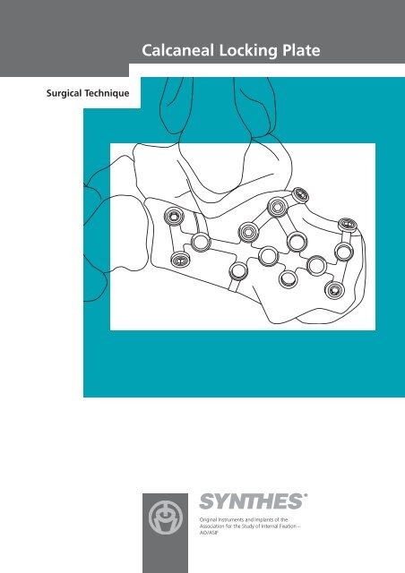
<strong>Calcaneal</strong> <strong>Locking</strong> <strong>Plate</strong>Table of contentsIndications 3Implants 4Instruments 5Surgical technique 6Implant removal 11Image intensifier controlWarningThis description is not sufficient for immediate applicationof the instrumentation. Instruction by a surgeon experiencedin handling this instrumentation is highly recommended.SYNTHES 1
<strong>Calcaneal</strong> <strong>Locking</strong> <strong>Plate</strong>Indications– Extra- and intra-articular calcaneal fractures– Multifragment calcaneal fractures–Tongue-type fractures– Joint depression fracturesSYNTHES 3
<strong>Calcaneal</strong> <strong>Locking</strong> <strong>Plate</strong>Implants<strong>Plate</strong>s– <strong>Calcaneal</strong> <strong>Locking</strong> <strong>Plate</strong> right, 69 mm (X41.622)– <strong>Calcaneal</strong> <strong>Locking</strong> <strong>Plate</strong> left, 69 mm (X41.623)– <strong>Calcaneal</strong> <strong>Locking</strong> <strong>Plate</strong> right, 76 mm (X41.624)– <strong>Calcaneal</strong> <strong>Locking</strong> <strong>Plate</strong> left, 76 mm (X41.625)LCP locking screws– LCP <strong>Locking</strong> Screw 3.5 mm, self-tapping(X13.010–060)– LCP <strong>Locking</strong> Screw Stardrive ® 3.5 mm, self-tapping(X12.101–124)Standard screws– Cortex Screw 2.7 mm, self-tapping(X02.820–860)– Cortex Screw 3.5 mm, self-tapping(X04.810–860)4
<strong>Calcaneal</strong> <strong>Locking</strong> <strong>Plate</strong>InstrumentsBending templates– Bending Template for <strong>Calcaneal</strong> <strong>Locking</strong> <strong>Plate</strong>, 69 mm(329.607)– Bending Template for <strong>Calcaneal</strong> <strong>Locking</strong> <strong>Plate</strong>, 76 mm(329.608)Cutting instrument– Cutting Pliers with Positioning Pin (329.151)Bending instruments– Bending Pliers for <strong>Plate</strong>s (391.963)– Bending Pin for LCP <strong>Plate</strong>s 3.5, with Thread (329.916)Note: The LCP standard instruments and LCP small fragmentinstruments are not listed.SYNTHES 5
<strong>Calcaneal</strong> <strong>Locking</strong> <strong>Plate</strong>Surgical technique1Surgical accessWith the patient in the lateral position, start with an extended,almost right-angled, lateral skin incision. The vertical partof the incision should run just in front of the Achilles tendonand turn with a slight curve to run horizontally along theplantar aspect. The calcaneo-cuboid joint can be reached byextending the incision distally. The skin incision should extenddown to the bone so that a complete flap consisting ofskin and subcutaneous tissue, and containing the peronealtendon, the sural nerve and the detached calcaneofibularligament, can be lifted off the periosteal surface.Alternatively, a no-touch technique, in the sense of theavoidance of constant hook retraction, can be used in whichthe flap is retracted using Kirschner wires inserted into thetalus and cuboid.Note: Prolonged traction on the flap should be avoided,particularly if Kirschner wires are used.2Reduce fractureReduce the fracture under direct vision or under the imageintensifier, and fix temporarily using Kirschner wires or reductionforceps. If Kirschner wires are used as a reduction aid,ensure that they do not interfere with the anatomically correctinsertion of the plate. A bending template (329.607/608)can be used as a guide.Precise reduction of the fracture can also be achieved bymanipulating a Schanz screw, using the universal chuck withT-handle, in the tuber fragment via a dorsal stab incision.6
3Adapt bending template (optional)Place the bending template on the calcaneus, check thelength and contour the template.4Cut plateCut the plate to match the anatomical requirements usingthe Cutting Pliers with Positioning Pin (329.151). Individualholes and either, or both, tabs on the plate can be cut off.To ensure a clean cut, position the plate in the cutting pliersas shown in the illustration. For correct orientation of theplate in the cutting pliers, the positioning pin must be insertedthrough the plate hole adjacent to the cut. Only one holecan be cut per cutting operation. If a pair of cutting plierswith positioning pin is not available, use the Cutting Pliersfor <strong>Plate</strong>s (391.931).5Bend tabsIn order to take account of the soft tissue situation at thecalcaneus, the tabs must be bent before the plate is placedagainst the bone. Bend the tabs in stages using the BendingPliers for <strong>Plate</strong>s (391.963) until the desired shape isachieved. Do not bend the tabs back and forth repeatedly.Note: The proximal tab on the plate should be bent andapplied at the level of Gissane’s angle so that it applies downwardpressure on the fragment of the anterior calcanealprocess.SYNTHES 7
6Contour plateContour the plate with the bending pliers, taking care not todeform the threaded holes, otherwise problems may ariseduring insertion of the LCP locking screws. If possible, bendthe plate between the holes.The Bending Pins (329.916) can be used to adapt the bentplate optimally during the operation. Screw one bendingpin into the desired hole and a second bending pin into theadjacent hole. Bend the plate as desired using the minimumamount of force.The reduction can be maintained even if the plate is notbent sufficiently. Since a LCP locking screw does not behavelike a lag screw, any tendency of the fracture fragment ofbeing pulled up is avoided.Notes:– Do not bend the plate more than 25–30° and do not bend itback and forth.– Do not bend the plate with the centering sleeve as this maydamage the sleeve.– Never bend the plate along its longitudinal axis.7Determine screw type and diameterSelect cortex screws 2.7 mm or 3.5 mm or LCP lockingscrews 3.5 mm. Both screw types may be combined ifdesired.Note: If both cortex and LCP locking screws are used inone plate, the cortex screws must be inserted first in orderto compress the plate against the bone.8
<strong>Calcaneal</strong> <strong>Locking</strong> <strong>Plate</strong>Surgical Technique8Predrill screw holesa. When predrilling for standard screws with the UniversalDrill Guide (323.260 or 323.360) and the matching bit,predrill the screw hole neutrally.Use the following bits:For cortex screw 2.7 mm: Drill Bit 2.0 mm(310.190 or 310.210)For cortex screw 3.5 mm: Drill Bit 2.5 mm(310.230 or 310.250)Note: When using a cortex screw 2.7 mm or 3.5 mmas a lag screw, predrill the cortex of the nearby fragment witha larger bit (Drill Bit 2.7 mm [310.260] for cortex screw 2.7 mm; Drill Bit 3.5 mm [310.350] for cortex screw 3.5 mm).b. When predrilling for LCP locking screws, screw the LCPDrill Sleeve 3.5 (323.027) into the desired threaded hole untilthe sleeve is fully gripped by the thread.The LCP drill sleeve ensures that the LCP locking screwis correctly locked in the plate. The angular stability is reducedif the LCP locking screw is inserted obliquely.Use the following drill bits:For LCP locking screw 3.5 mm: Drill Bit 2.8 mm(310.284)Note: If a gap between the lateral and medial posteriorfacets is apparent under the image intensifier, short-threadedcancellous bone screws instead of LCP locking screws shouldbe inserted subthalamically.9Determine screw lengthDetermine the screw length with the Depth Gauge (319.010).SYNTHES 9
10Insert screwsStandard screwsInsert the cortex screws with the small, hexagonal Screwdriver 2.5 mm (314.070).LCP locking screwsThe LCP locking screws can be inserted mechanically or byhand.a. To insert the LCP locking screws mechanically, attach theTorque Limiter 1.5 Nm (511.770) to the power tool unit(Compact Air Drive 511.701 or Power Drive 530.100). Insertthe Hexagonal Screwdriver Shaft (314.030) or the Stardrive ®Screwdriver Shaft 3.5 (314.116) into the torque limiter.Pick up the LCP locking screw and insert it into the plate hole.To insert the screw, start the power tool unit slowly, increasethe speed and then reduce again before the screw is fullytightened. The torque is automatically limited and a clearlyaudible click signifies that the maximum level has beenreached. Stop the power tool unit immediately and disconnectfrom the screw.Notes: Do not lock the screw at full speed as this risksdamaging the hexagonal or Stardrive recess, making implantremoval more difficult.Ensure that adequate cooling is provided when inserting fairlylong screws into thick cortical bone.With porous bone there is a risk that the LCP locking screwfails to follow the predrilled hole, resulting in a slightly obliquehole during mechanical insertion of the screw with subsequentpartial loss of angular stability. In case of porous bone,manual locking (with the handle for torque limiter) of thescrews is recommended to ensure better guidance throughthe predrilled hole.b. To insert the LCP locking screws manually, attachthe torque limiter 1.5 Nm to the Handle for Torque Limiter(397.705) and insert the screwdriver shaft.Lock the LCP locking screws in the plate.10
<strong>Calcaneal</strong> <strong>Locking</strong> <strong>Plate</strong>Implant removalTo remove the plate, first unlock all screws before removingthem definitively in a second step, otherwise the platemay rotate while the last screw is being removed and causesoft tissue damage.If the screws cannot be removed with the screwdriver (e.g.if the hexagonal or Stardrive recess of the LCP locking screwis damaged or if the screws are stuck in the plate), insert theConical Extraction Screw with Left-handed Thread (309.521)in the screw head using the T-handle with Quick Coupling(311.440) and loosen the locking screw by turning counterclockwise.SYNTHES 11