Green'-synthesized near-infrared PbS quantum dots with silica--PEG ...
Green'-synthesized near-infrared PbS quantum dots with silica--PEG ...
Green'-synthesized near-infrared PbS quantum dots with silica--PEG ...

You also want an ePaper? Increase the reach of your titles
YUMPU automatically turns print PDFs into web optimized ePapers that Google loves.
Home Search Collections Journals About Contact us My IOPscience‘Green’-<strong>synthesized</strong> <strong>near</strong>-<strong>infrared</strong> <strong>PbS</strong> <strong>quantum</strong> <strong>dots</strong> <strong>with</strong> <strong>silica</strong>–<strong>PEG</strong> dual-layer coating:ultrastable and biocompatible optical probes for in vivo animal imagingThis article has been downloaded from IOPscience. Please scroll down to see the full text article.2012 Nanotechnology 23 245701(http://iopscience.iop.org/0957-4484/23/24/245701)View the table of contents for this issue, or go to the journal homepage for moreDownload details:IP Address: 210.32.152.202The article was downloaded on 29/05/2012 at 03:13Please note that terms and conditions apply.
IOP PUBLISHINGNanotechnology 23 (2012) 245701 (9pp)NANOTECHNOLOGYdoi:10.1088/0957-4484/23/24/245701‘Green’-<strong>synthesized</strong> <strong>near</strong>-<strong>infrared</strong> <strong>PbS</strong><strong>quantum</strong> <strong>dots</strong> <strong>with</strong> <strong>silica</strong>–<strong>PEG</strong> dual-layercoating: ultrastable and biocompatibleoptical probes for in vivo animal imagingD Wang 1,2,4 , J Qian 1,2,4 , F Cai 1,2 , S He 1,2 , S Han 3 and Y Mu 31 Centre for Optical and Electromagnetic Research, Zhejiang Provincial Key Laboratory for SensingTechnologies, Zhejiang University, Hangzhou 310058, People’s Republic of China2 JORCEP (Joint Research Center of Photonics of the Royal Institute of Technology (Sweden), LundUniversity (Sweden) and Zhejiang University), Zhejiang University, Hangzhou 310058, People’sRepublic of China3 Research Center for Analytical Instrumentation, Institute of Cyber-Systems and Control, State KeyLaboratory of Industrial Control Technology, Zhejiang University, Hangzhou 310058, People’s Republicof China4 Joint Research Laboratory of Optics of Zhejiang Normal University and Zhejiang University,Hangzhou 310058, People’s Republic of ChinaE-mail: sailing@kth.se (S He)Received 15 January 2012, in final form 9 April 2012Published 28 May 2012Online at stacks.iop.org/Nano/23/245701AbstractIn this paper, <strong>PbS</strong> semiconductor <strong>quantum</strong> <strong>dots</strong> (QDs) <strong>with</strong> <strong>near</strong>-<strong>infrared</strong> (NIR)photoluminescence were <strong>synthesized</strong> in oleic acid and paraffin liquid mixture by using aneasily handled and ‘green’ approach. Surface functionalization of the QDs was accomplished<strong>with</strong> a <strong>silica</strong> and polyethylene glycol (<strong>PEG</strong>) phospholipid dual-layer coating and the excellentchemical stability of the nanoparticles is demonstrated. We then successfully applied theultrastable <strong>PbS</strong> QDs to in vivo sentinel lymph node (SLN) mapping of mice. Histologicalanalyses were also carried out to ensure that the intravenously injected nanoparticles did notproduce any toxicity to the organism of mice. These experimental results suggested that ourultrastable NIR <strong>PbS</strong> QDs can serve as biocompatible and efficient probes for in vivo opticalbioimaging and has great potentials for disease diagnosis and clinical therapies in the future.(Some figures may appear in colour only in the online journal)1. IntroductionThe use of colloidal semiconductor <strong>quantum</strong> <strong>dots</strong> (QDs) asluminescence probes in bioimaging has attracted tremendousattention due to their excellent properties [1–4]. It is wellknown that the best spectral region (‘optical transmissionwindow’) for biological tissue imaging is in the <strong>near</strong>-<strong>infrared</strong>(NIR) range (∼700–1000 nm) [5–7]. In the past few years,several kinds of NIR QDs have been reported and some ofthem have been applied to in vivo biomedical applicationsand achieved exciting results [8–13]. Among the most popularQDs currently used, <strong>PbS</strong> QDs are especially interestingbecause of their unique and unusual properties. (1) With alarge exciton Bohr radii of 20 nm for <strong>PbS</strong>, the electron andhole contribute equally to the exciton Bohr radii, leadingto enhanced confinement of both carriers [14]. (2) Theprincipal ore of lead (galena) is a naturally occurring mineral<strong>with</strong> highly symmetrical sodium chloride structure whereevery atom occupies a point of inversion. (3) They displayferroelectric effects and have large optical dielectric constant,and narrow fundamental bandgaps. (4) They possess negativepressure coefficients and large static dielectric constants [15].0957-4484/12/245701+09$33.00 1c○ 2012 IOP Publishing Ltd Printed in the UK & the USA
Nanotechnology 23 (2012) 245701Many applications of <strong>PbS</strong> QDs in the area of optoelectronicshave been studied [16–20], while the use of <strong>PbS</strong> QDs foroptical bioimaging are limited, because many works onthe synthesis of <strong>PbS</strong> QDs are for large size <strong>with</strong> differentmorphologies and the resulting <strong>PbS</strong> QDs exhibit emissionin the range of 1000–1400 nm. In 2009, Liu et al [21]developed a non-injection and low-temperature approach toproduce high-quality <strong>PbS</strong> QDs <strong>with</strong> a bandgap in the rangeof 600–900 nm, making <strong>PbS</strong> QDs a promising candidate forNIR biomedical imaging in living tissues. However, the maindisadvantage of QDs currently used is that most syntheticmethods for these QDs require environmental noxiousreagents. In recent years, Zou and co-workers developeda ‘green’ synthesis method [22, 23] for the preparation ofzinc blende CdSe nanocrystals, which opened a non-toxicsynthesis of QDs in the world.Another challenge for the application of QDs forin vivo bioimaging is to keep their long-term chemicalstability and biocompatibility under different harsh bioenvironments.Various reports can been found on QDencapsulation technologies based on the surface modificationof small-molecule ligands [24], <strong>silica</strong> [25] and amphiphilicpolymers [26–29] to produce highly water-soluble and brightQDs. Very recently, Gao et al [30] developed a newstrategy for preparation of ultrastable QDs by combining twocurrent encapsulation technologies based on <strong>silica</strong> shells andamphiphilic polymers. Their studies gave a new approach forthe surface functionalization of QDs.In the present paper, we reported the synthesis of NIR<strong>PbS</strong> QDs through a green route using paraffin liquid as thesolvent. The advantages of our protocol are the following. (1)Our synthesis route is easy and the as-used solvents, oleicacid and paraffin liquid, are both natural products. (2) Theobtained <strong>PbS</strong> QDs exhibit emission in the NIR range and isvery compatible for in vivo bioimaging. The as-<strong>synthesized</strong>oleic-acid-capped <strong>PbS</strong> QDs was functionalized <strong>with</strong> a<strong>silica</strong>–polymer dual-layer coating method and hydrophilicNIR nanoparticles (<strong>PbS</strong>@SiO 2 @<strong>PEG</strong>) were then achieved.Compared <strong>with</strong> the traditional surface capping methods(e.g. <strong>silica</strong> or amphiphilic polymer coating alone), a<strong>silica</strong>–polymer dual layer can greatly improve the stabilityof <strong>PbS</strong> QDs, as well as prevent the leakage of ionized Pb 2+from <strong>PbS</strong> QDs to the bio-surroundings, which can effectivelyeliminate their cytotoxicity. Furthermore, the presence of <strong>PEG</strong>chains in <strong>PbS</strong>@SiO 2 @<strong>PEG</strong> nanoparticles not only makesthe nanoparticles water-dispersible, but can also improvetheir long-time circulation in an animal body [31]. Wethen used these ultrastable NIR fluorescent nanoparticles asefficient optical probes for in vivo sentinel lymph node (SLN)mapping, which at present is a key process in SLN biopsy(SLNB) for breast cancer surgery [32] and real-time opticalimages <strong>with</strong> high SNR (signal-to-noise ratio) were obtained.2. Experimental methods2.1. Materials and instrumentsLead acetate trihydrate (PbAc 2·3H 2 O), trimethylsilyl sulfide((TMS) 2 S), tetraethyl ortho<strong>silica</strong>te (TEOS), IGEPALD Wang et alCO-520, trimethoxy(octadecyl)silane (OTMS), blood serum(from goat) and biotin were purchased from Sigma-Aldrich. 1,2-distearoyl-sn-glycero-3-phosphoethanolamine-N-[methoxy(polyethylene glycol)-5000] (<strong>PEG</strong>) was purchasedfrom Creative <strong>PEG</strong>Works, Inc. Oleic acid (OA),paraffin liquid (chemical grade, <strong>with</strong> a boiling pointabove 300 ◦ C), cyclohexane, methanol, ethanol, ammoniumhydroxide, phosphate buffered saline (PBS), hydrochloricacid, sodium hydroxide and pentobarbital were obtained fromthe Chemical Reagent Department of Zhejiang University.All the reagents were of analytical grade unless specificallyindicated otherwise, and DI water was used in all theexperimental procedures. TEM images were taken by a JEOLJEM-1230 transmission electron microscope operating at160 kV in bright-field mode. Powder XRD patterns wererecorded at room temperature on a Bruker Axs D8 Advancex-ray diffractometer using Cu Kα radiation in a θ–θ mode.The generator was operated at 40 kV and 40 mA, anddata were collected between 10 and 90 ◦ in 2θ <strong>with</strong> a stepsize of 0.02 ◦ and a counting time of 10 s per step. XRDsamples were prepared by depositing the purified <strong>PbS</strong> QDson low-background quartz plates. Dynamic light scattering(DLS) analysis was conducted using a Dawn R○ Heleos lightscatterer from Wyatt Technology Corp at room temperature.The UV–vis absorption spectra of the samples <strong>with</strong>inthe wavelength region of 600–900 nm were recordedby a Shimadzu 2550 UV–vis scanning spectrophotometer.Fluorescence spectra of the samples <strong>with</strong>in the wavelengthregion of 800–1100 nm were measured <strong>with</strong> a BWTEKRaman probe. The concentrations of Pb in different solutionswere measured by a MKIIM6 flame atomic absorptionspectrometer. Data were acquired using a delay time of 4 sfollowed by triplicate integration times of 4 s each. Standardsfor lead were prepared by digesting the ion in 0.1 M nitricacid.2.2. Synthesis of <strong>PbS</strong> QDsFirst, for the preparation of a Pb precursor solution, 1.52 g(4 mmol) of lead acetate trihydrate (PbAc 2·3H 2 O), 2.5 ml(8 mmol) oleic acid and 37.5 ml paraffin liquid were loadedinto a 250 ml three-neck reaction flask. The flask wasdegassed at room temperature for 30 min and was heatedup to 120 ◦ C under vacuum. After one hour, a bright yellowsolution (solution A, Pb precursor) was formed. Second, forthe preparation of an S-precursor solution, 2 ml of paraffinliquid was loaded in a 100 ml three-neck reaction flask anddegassed for one hour under vacuum. Afterwards, 42 µl(0.2 mmol) of (TMS) 2 S was added under the protection ofN 2 and the resulting solution in paraffin liquid was stirredfor 10 min to form a homogeneous solution (solution B,S precursor). For the preparation of <strong>PbS</strong> QDs, 4 ml ofsolution A (containing about 0.4 mmol Pb-precursor) wasquickly taken out <strong>with</strong> a syringe and injected into solution B<strong>with</strong> continuous stirring. The temperature of the mixture waskept at 40 ◦ C for the QDs’ growth. After 30 min, methanolwas added to precipitate <strong>PbS</strong> QDs. The precipitated <strong>PbS</strong>QDs were separated by centrifugation, further washed <strong>with</strong>chloroform several times and dried at room temperature forcharacterization or redispersed in chloroform for reservation.2
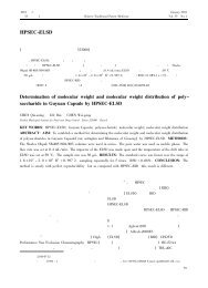
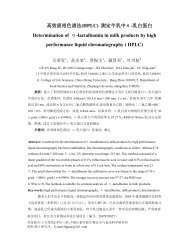
Nanotechnology 23 (2012) 2457012.3. Silica–<strong>PEG</strong> dual-layer coating of <strong>PbS</strong> QDs2.5. Histological analysisD Wang et alBriefly, 1.3 ml of IGEPAL CO-520 was added to 10 mlof cyclohexane, followed by the addition of 300 µl <strong>PbS</strong>QD solution (1 mg ml −1 in chloroform), 80 µl TEOS and150 µl ammonia aqueous solution. Between each chemicaladdition, the reaction mixture was stirred for 10 min. The finalmixture solution was stirred continuously for 24 h. After the<strong>silica</strong> condensation reaction, the resulting <strong>silica</strong>-coated <strong>PbS</strong>QDs (<strong>PbS</strong>@SiO 2 ) were isolated from the microemulsion bythe addition of ethanol (3 ml) followed by centrifugation at6000 rpm for 10 min. The resulting <strong>PbS</strong>@SiO 2 nanoparticleswere repeatedly rinsed <strong>with</strong> ethanol and finally dispersed in10 ml ethanol. The <strong>PbS</strong>@SiO 2 ethanol solution (10 ml) wasmixed <strong>with</strong> 0.1 ml of ammonia solution to adjust the pHto 9. Then, 1 ml of OTMS solution (10% in chloroform)was added dropwise to the nanoparticle suspension undervigorous stirring. After 24 h, the particles were separated<strong>with</strong> centrifugation (10 min at 9000 rpm), washed twice<strong>with</strong> ethanol and dispersed in 10 ml chloroform. In the laststep, OTMS-coated <strong>PbS</strong>@SiO 2 nanoparticles were dispersedin chloroform and 40 mg DSPE-<strong>PEG</strong> (10 mg ml −1 inchloroform) was added. The mixture was sonicated for 5 minand then evaporated under vacuum in a rotary evaporator,after which the residuum was gently heated at 40 ◦ C. Theremaining nanoparticle film was then dispersed in DI water<strong>with</strong> sonication. The solution was centrifuged for 10 min at12 000 rpm to remove empty micelles (repeated three times)and redispersed in 1 ml DI water. After that, an optically clearsuspension containing <strong>silica</strong>–polymer dual-layer coating of<strong>PbS</strong> QDs (<strong>PbS</strong>@SiO 2 @<strong>PEG</strong>) was obtained.2.4. Biocompatibility and chemical stability testsSilica-coated <strong>PbS</strong> QDs (<strong>PbS</strong>@SiO 2 ), <strong>PEG</strong>-coated <strong>PbS</strong>QDs (<strong>PbS</strong>@<strong>PEG</strong>) and <strong>PEG</strong>ylated <strong>silica</strong>-coated <strong>PbS</strong> QDs(<strong>PbS</strong>@SiO 2 -<strong>PEG</strong>) were selected for stability comparison <strong>with</strong><strong>PbS</strong>@SiO 2 @<strong>PEG</strong> nanoparticles. <strong>PEG</strong>-coated <strong>PbS</strong> QDs weremade according to the procedure of adding 60 mg DSPE-<strong>PEG</strong>(10 mg ml −1 in chloroform) to 300 µl <strong>PbS</strong> QD solution(1 mg ml −1 in chloroform) and the mixture was evaporatedand redispersed in DI water. The <strong>silica</strong>-coated <strong>PbS</strong> QDswere treated in the same way as that of the <strong>PbS</strong>@SiO 2nanoparticles. Solutions <strong>with</strong> pH values of 2 and 12 weretuned <strong>with</strong> hydrochloric acid or sodium hydroxide. Phosphatebuffered saline (1 × PBS, pH = 7.4), blood serum and biotinsolutions <strong>with</strong> a concentration of 0.05 mg ml −1 was prepared.<strong>PbS</strong> QDs <strong>with</strong> various surface coatings were then incubated<strong>with</strong> these solutions and fluorescence intensities of eachsolution at various time points were monitored. To confirmthe release of Pb from <strong>PbS</strong>@SiO 2 @<strong>PEG</strong> nanoparticles,the particles incubated <strong>with</strong> different solutions (e.g. PBS,blood serum, 0.05 mg ml −1 biotin, solution <strong>with</strong> pH =2 and pH = 12) for four days were spin-filtered using amicrofuge membrane filter (NANOSEP 100 K OMEGA, PallCorporation, USA) at 10 000 rpm for 10 min. The filtratedsolution, which passed through the membrane, was collected.The concentrations of Pb in the filtrated solutions weremeasured by atomic absorption spectroscopy (AAS).Five experimental mice were injected <strong>with</strong> <strong>PbS</strong>@SiO 2 @<strong>PEG</strong>(300 µl per mouse, 1 mg ml −1 in 1 × PBS, pH = 7.4)through tail vein and five non-injected mice were used asthe control. Fifteen days after the treatment, the experimentalmice, as well as control mice, were put down and their majororgans (heart, liver, lung, kidney and spleen) were removedfor histological analysis. Tissues were fixed in 10% formalin,embedded in paraffin, sectioned and stained <strong>with</strong> hematoxylinand eosin. The histological sections were imaged under aninverted optical microscope (100×).2.6. In vivo animal studiesAll in vivo experiments were performed in compliance <strong>with</strong>Zhejiang University Animal Study Committee’s requirementsfor the care and use of laboratory animals in our research.Five nude mice (18–21 g, male) were used for animalimaging studies. Every time before imaging, the micewere anesthetized <strong>with</strong> intraperitoneal injection of 0.5%pentobarbital sodium.3. Results and discussion3.1. Characterization of <strong>PbS</strong>@SiO 2 @<strong>PEG</strong> nanoparticlesFigure 1 illustrates the major steps in preparing <strong>PbS</strong>@SiO 2@<strong>PEG</strong> nanoparticles and the chemical structures of themain molecules used in the experiment. By modifyingLiu’s method [21], we developed an easily handled ‘green’route for the synthesis of high-quality <strong>PbS</strong> QDs. In ourmethod, Pb precursor was added to the sulfur solution (Sprecursor), by using paraffin liquid (instead of octadecene(ODE)) as the solvent (see details in section 2). Sinceparaffin liquid is more cost-effective, environmentally friendlyand chemically stable in the atmosphere than ODE [22],we believe that our modification is of great value forboth laboratory research and industrial applications. For<strong>silica</strong>–polymer dual-layer coating on <strong>PbS</strong> QDs, we adopteda double phase-transfer procedure as described in earlierliterature [21]. The as-<strong>synthesized</strong> oleic-acid-capped <strong>PbS</strong>QDs were first encapsulated <strong>with</strong> <strong>silica</strong> shells (<strong>PbS</strong>@SiO 2 )using a reverse microemulsion method [33, 34]. Then thehydrophilic <strong>PbS</strong>@SiO 2 nanoparticles were converted backto hydrophobic by reacting <strong>with</strong> trimethoxy(octadecyl)silane(OTMS) to graft long-chain hydrocarbons on the surface ofthe <strong>silica</strong> shell. Finally, the hydrophobic <strong>PbS</strong>@SiO 2 @OTMSnanoparticles were transferred to hydrophilic again <strong>with</strong>amphiphilic lipid–<strong>PEG</strong> molecules (<strong>PbS</strong>@SiO 2 @<strong>PEG</strong>).Transmission electron microscopy (TEM) image infigure 2(A) indicates that the as-<strong>synthesized</strong> <strong>PbS</strong> QDswere mono-distributed <strong>with</strong> an average size of 3.0 nm.Powder x-ray diffraction (XRD) patterns of the <strong>PbS</strong> QDs infigure 2(D) show unambiguous evidence that the particleshad a bulk cubic rocksalt structure. One thing worth notingis that the XRD peaks of the as-<strong>synthesized</strong> <strong>PbS</strong> QDs wereconsiderably broadened compared to those of the bulk cubic3
Nanotechnology 23 (2012) 245701D Wang et alFigure 1. Schematic diagram illustrating the preparation of (1) <strong>PbS</strong> QDs capped <strong>with</strong> oleic acid, (2) <strong>silica</strong>-coated <strong>PbS</strong> QDs, (3)hydrophobic-modified <strong>PbS</strong>@SiO 2 via OTMS grafting and (4) hydrophilic <strong>PbS</strong>@SiO 2 @<strong>PEG</strong> nanoparticles. Chemical structures of somemolecules used are also shown.rocksalt <strong>PbS</strong>; we attribute the broadness of diffraction peaksto the small size of <strong>PbS</strong> QDs. The TEM images in figures 2(B)and (C) suggest that both <strong>PbS</strong>@SiO 2 nanoparticles and<strong>PbS</strong>@SiO 2 @<strong>PEG</strong> nanoparticles were well dispersed, <strong>with</strong>uniform diameters of 35–45 nm. The monodispersity ofnanoparticles in an aqueous environment was also confirmedby dynamic light scattering (DLS) measurements. TheDLS result in figure 2(E) shows that <strong>PbS</strong>@SiO 2 @<strong>PEG</strong>nanoparticles (dashed line) have a hydrodynamic diameter of54.1 ± 9.8 nm, which was larger than that (35–45 nm) of thedry nanoparticles observed in the TEM (figure 2(C) and thehydrodynamic diameter of <strong>PbS</strong>@SiO 2 nanoparticles in water(figure 2(E), solid line). This phenomenon can be attributed tothe lipid–<strong>PEG</strong> structure of the shell or the net surface chargessurrounding the nanoparticles [35].Normalized UV–vis absorption and fluorescence spectraof <strong>PbS</strong> QDs dispersed in chloroform and <strong>PbS</strong>@SiO 2 @<strong>PEG</strong>nanoparticles dispersed in water are presented in figure 3.It is clear that the absorption spectrum of <strong>PbS</strong>@SiO 2 @<strong>PEG</strong>nanoparticles in aqueous solution was similar to that of theoriginal <strong>PbS</strong> QDs in organic solvent, <strong>with</strong> an absorbancepeak at 850 nm. However, compared to the oleic-acid-capped<strong>PbS</strong> QDs, the normalized fluorescence peaks of <strong>PbS</strong>@SiO 2nanoparticles and <strong>PbS</strong>@SiO 2 @<strong>PEG</strong> nanoparticles obviouslyshifted to short wavelengths from 923 to 903 nm, whichwas due to the <strong>silica</strong> coating of <strong>PbS</strong> nanoparticles andthe difference of the solvents. Both the absorbance peakand the fluorescence peak are in the NIR range, wherethe lower absorption of the excitation light allows deeppenetration of light for deep-tissue imaging, and thereduced autofluorescence of biological tissues helps to obtainfluorescence images <strong>with</strong> high contrast.3.2. Stability of <strong>PbS</strong>@SiO 2 @<strong>PEG</strong> nanoparticlesAs a kind of potential fluorescent probes for biologicalapplications, QDs should be stable in a wide range ofpH values and common bioconjugation reagents. Otherwise,monodispersed nanoparticles may be transformed intoclusters of nanoparticles, which are too large to be takenup by cells, as well as unable to circulate smoothlyin the vessels for in vivo experiments. To confirm thebiological and chemical stabilities of our <strong>PbS</strong>@SiO 2 @<strong>PEG</strong>nanoparticles, we systematically studied the fluorescenceintensity changes of various <strong>PbS</strong> QDs <strong>with</strong> differentsurface coatings (e.g. <strong>PbS</strong>@SiO 2 , <strong>PbS</strong>@<strong>PEG</strong>, <strong>PbS</strong>@SiO 2 -<strong>PEG</strong> and <strong>PbS</strong>@SiO 2 @<strong>PEG</strong>) under different chemicaltreatments (e.g. phosphate buffered saline (PBS), bloodserum, 0.05 mg ml −1 biotin, solution <strong>with</strong> pH = 2 and 12).Here, the <strong>PEG</strong>ylated <strong>PbS</strong>-labeled nanoparticles (<strong>PbS</strong>@SiO 2 -<strong>PEG</strong>) were <strong>synthesized</strong> using bis(silylated)polyethyleneglycol for growth of a <strong>PEG</strong>ylated SiO 2 shell [36]. The4
Nanotechnology 23 (2012) 245701D Wang et alFigure 2. TEM images of (A) oleic-acid-capped <strong>PbS</strong> QDs dispersed in chloroform, (B) <strong>PbS</strong>@SiO 2 nanoparticles dispersed in water. (C)<strong>PbS</strong>@SiO 2 @<strong>PEG</strong> nanoparticles dispersed in water. (D) Powder XRD patterns of <strong>PbS</strong> QDs (top) and the vertical bars of bulk cubic rock salt<strong>PbS</strong> (bottom) corresponding to JCPDS file no. 05-0592. (E) DLS measurement of <strong>PbS</strong>@SiO 2 nanoparticles and <strong>PbS</strong>@SiO 2 @<strong>PEG</strong>nanoparticles.Figure 3. Normalized UV–vis absorption (left) and fluorescencespectra (right) of <strong>PbS</strong> QDs dispersed in chloroform (solid line),<strong>PbS</strong>@SiO 2 nanoparticles (dotted line) and <strong>PbS</strong>@SiO 2 @<strong>PEG</strong>nanoparticles dispersed in water (dashed line). A 785 nm diode laser(100 mW) was adopted for fluorescence excitation.solutions and concentrations were selected <strong>with</strong> considerationof the most basic environments in the human body: PBSis a buffer solution commonly used in biological research;blood serum is used to simulate the bio-environments of invivo experiments; biotin is a type of common bioconjugationreagent; pH = 2 and 12 are the limit values of pH valuesfound in the human body. Figure 4(A) shows the fluorescenceintensity of <strong>PbS</strong> QDs <strong>with</strong> various surface coatingsafter being incubated <strong>with</strong> different solutions for 24 h.Notably, the fluorescence intensities of <strong>PbS</strong>@SiO 2 @<strong>PEG</strong>nanoparticles changed less than 10% in any mentionedcondition, while other QD specimens exhibited obviousdeterioration in optical properties. The fluorescence intensityof <strong>PbS</strong>@SiO 2 @<strong>PEG</strong> nanoparticles under different chemicaltreatments were monitored for four days and the resultsare shown in figure 4(B). From these results, we canconclude that, compared <strong>with</strong> the traditional surface cappingmethods, <strong>PbS</strong> QDs <strong>with</strong> <strong>silica</strong>–polymer dual-layer protectionexhibited remarkable stability. In addition, according to ourexperimental experience, <strong>PbS</strong> QDs <strong>with</strong> direct lipid–<strong>PEG</strong>coating had much lower fluorescence intensity than theoriginal hydrophobic <strong>PbS</strong> QDs, while <strong>PbS</strong> QDs coated <strong>with</strong>only a <strong>silica</strong> layer could not be well dispersed in water formore than two days. The size distributions (figure 4(B), inset)indicated no aggregation of <strong>PbS</strong>@SiO 2 @<strong>PEG</strong> nanoparticlesunder different conditions after four days. The AAS resultsin table 1 showed little release of Pb from <strong>PbS</strong>@SiO 2 @<strong>PEG</strong>nanoparticles, which are very positive for the stability ofthe nanoparticles. Although we cannot entirely explain themechanism of this high-level protection by the <strong>silica</strong>–polymerdual-layer coating at this time, the experimental resultsare very positive for the applications of <strong>PbS</strong>@SiO 2 @<strong>PEG</strong>nanoparticles as NIR nanoprobes for in vivo imaging.5
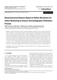
Nanotechnology 23 (2012) 245701D Wang et alABFigure 4. (A) Fluorescence intensity of <strong>PbS</strong> QDs <strong>with</strong> varioussurface coatings (<strong>PbS</strong>@SiO 2 , <strong>PbS</strong>@<strong>PEG</strong>, <strong>PbS</strong>@SiO 2 -<strong>PEG</strong> and<strong>PbS</strong>@SiO 2 @<strong>PEG</strong>), 24 h after treated <strong>with</strong> different solutions ofwater, PBS, blood serum, 0.05 mg ml −1 biotin, solution <strong>with</strong>pH = 2 and pH = 12, respectively. (B) Fluorescence intensity of<strong>PbS</strong>@SiO 2 @<strong>PEG</strong> nanoparticles, which were treated <strong>with</strong> differentsolutions of PBS, blood serum, 0.05 mg ml −1 biotin, solution <strong>with</strong>pH = 2 and 12 during four days (inset: size distributions of<strong>PbS</strong>@SiO 2 @<strong>PEG</strong> nanoparticles under different conditions afterfour days).Table 1. Typical results for concentration analysis of Pb in differentfiltrated solutions (Note: the concentration of Pb in originalsolutions before filtrate treatment was 628.3007 ± 3.8 mg l −1 .)Incubation solutions Concentrations (mg l −1 ) Rsd (%) aPBS 0.0019 >99Blood serum 0.0115 85.00.05 mg ml −1 biotin 0.0182 18.9pH = 2 0.0204 33.7pH = 12 0.0076 65.4a The large relative standard deviation was caused by the tinysignal of the sample.3.3. Physical and histological evaluations of<strong>PbS</strong>@SiO 2 @<strong>PEG</strong>-treated miceUltrastability, as well as NIR excitation and emission, suggestthe great potential for applications of <strong>PbS</strong>@SiO 2 @<strong>PEG</strong>nanoparticles for in vivo imaging and clinical diagnosis.Before any clinical applications, the most important thing isto ensure that the injected nanoparticles do not induce anytissue/organ toxicity [37]. For this, mice were intravenouslyinjected <strong>with</strong> <strong>PbS</strong>@SiO 2 @<strong>PEG</strong> nanoparticles (300 µl permouse, 1 mg ml −1 in 1 × PBS, pH = 7.4). As theFigure 5. Histological sections of heart, liver, spleen, kidney andlung samples, collected from a mouse receiving no injection (left)and a mouse injected <strong>with</strong> <strong>PbS</strong>@SiO 2 @<strong>PEG</strong> nanoparticles (right)15 days after treatment. Sections were observed under a lightmicroscope at 100× magnification.osmolarity and ion concentrations of the injected phosphatebuffered saline (PBS) solution usually match those of thebody, no noticeable pulmonary edema was observed in ourexperiments. There were no changes in eating, drinkingnor physical features of the injected mice over 15 daysobservation. Histological analyses of the major organs of mice<strong>with</strong> (as experimental mice) and <strong>with</strong>out (as control mice)intravenous injections of the <strong>PbS</strong>@SiO 2 @<strong>PEG</strong> nanoparticleswere also carried out. The results in figure 5 showed that therewere no apparent tissue/cellular differences in the main organs(heart, liver, spleen, kidney or lung) between the experimentalmice and the control mice. Although much work, such asthe biodistribution, the primary route of clearance and bloodtoxicity measurement, needs to be studied systematicallybefore the nanoparticles can be used in biomedicine, our pilotsmall-scale toxicity study is promising and these kind of QDsfor in vivo biomedical applications should be explored further.3.4. In vivo imaging and SLN mapping of miceTo determine whether the ultrastable <strong>PbS</strong>@SiO 2 @<strong>PEG</strong>nanoparticles could be used for NIR bioimaging of liveanimals, a nude mouse was first injected <strong>with</strong> 30 µl of6
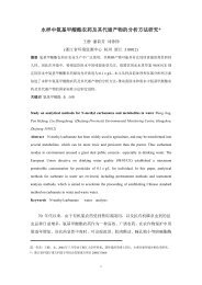
Nanotechnology 23 (2012) 245701D Wang et alFigure 6. Bright-field imaging (A) and NIR fluorescence imaging (B) of a nude mouse subcutaneously injected <strong>with</strong> <strong>PbS</strong>@SiO 2 @<strong>PEG</strong>nanoparticles. (C) NIR fluorescence spectra of the subcutaneously injected and non-injected skin, <strong>with</strong> fluorescence peak wavelengths of930 nm and 760 nm, respectively. Deep-red broadband light <strong>with</strong> a peak wavelength of 704 nm was used for fluorescence excitation.<strong>PbS</strong>@SiO 2 @<strong>PEG</strong> nanoparticles (1 mg ml −1 in 1 × PBS,pH = 7.4) into the skin of the back. A Maestro in vivooptical imaging system (CRI, Inc. Woburn, MA) was used forfluorescence imaging of the subcutaneously injected mouse.The excitation source was deep-red broadband light <strong>with</strong> apeak wavelength of 704 nm, and a liquid-crystal tunable filterwas automatically tuned <strong>with</strong> 10 nm increments from 740to 950 nm. A CCD camera, <strong>with</strong> a 740 nm long-pass filterin front to cut off the excitation light, was used to recordthe fluorescence intensity/image at each wavelength (exposuretime of 5000 ms). The resulting images were analyzed <strong>with</strong>the software package provided by CRI Inc. Figures 6(A)and (B) are the bright-field image and NIR fluorescence imageof the subcutaneously injected mouse. We can clearly observethe fluorescence signals from <strong>PbS</strong>@SiO 2 @<strong>PEG</strong> nanoparticlesin the injected sites. In contrast, the autofluorescence fromthe non-injected skin sites was very weak. Figure 6(C) showsthe fluorescence spectra from the sample-injected positionand non-injected skin. Obviously, the peak wavelength ofNIR signal (∼930 nm) is very different from that ofautofluorescence (∼760 nm), which is a key factor toobtain high contrast of in vivo fluorescence images. It isalso worth noting that the fluorescence peak wavelengthof <strong>PbS</strong>@SiO 2 @<strong>PEG</strong> nanoparticles in mice (∼930 nm) wasdifferent from that in aqueous solution (903 nm) and weattribute this difference to the complex bio-environment.Considering the high in vivo NIR fluorescence imagingcontrast of our <strong>PbS</strong>@SiO 2 @<strong>PEG</strong> nanoparticles, we investigatedtheir applicability in in vivo SLN mapping of mice.SLN is the hypothetical first lymph node or group of nodesreached by metastasizing cancer cells from a primary tumor.In recent years there has been a surge in the development SLNbiopsy technique, which is used in the staging of certain typesof cancer to see if they have spread to any lymph nodes, sincelymph node metastasis is one of the most important prognosticsigns. Accurate identification and biopsy of SLN can enableclinicians to focus on certain lymph nodes and perform moredetailed tracking of cancer cell diffusion. In 1999, isosulfanblue dye was used as trackers in the early studies of thesentinel node technique by Little et al [38], but the primarydrawback of blue dye is that the emission wavelength does notpenetrate far into soft tissue. In 2004, Kim et al proved thatNIR type II QDs can be used effectively for SLN mappingin large animals and the NIR signals could be detected ata depth of up to 1 cm in the tissue [39]. Subsequently,Song et al used gold nanocages to absorb NIR light fornon-invasive SLN detection in photoacoustic imaging [40].Kim et al used conjugated polymer nanoparticles as probes forreal-time in vivo SLN mapping in mouse [41]. SLN imagingbased on the use of NIR fluorophores as labeling agentshas become an area of intense research focus and forms amajor thrust of bio-photonics. The excellent chemical stabilityof ‘green’-<strong>synthesized</strong> NIR <strong>PbS</strong> <strong>quantum</strong> <strong>dots</strong> motivated usto investigate their applicability in in vivo SLN mapping.In our experiment, <strong>PbS</strong>@SiO 2 @<strong>PEG</strong> samples (100 µl permouse, 1 mg ml −1 in 1 × PBS, pH = 7.4) were intradermallyinjected into the left forepaw pad of mice. In vivo fluorescenceimaging was performed immediately after sample injection,by utilizing the Maestro in vivo optical imaging system.When the <strong>PbS</strong>@SiO 2 @<strong>PEG</strong> nanoparticles were injectedintradermally into the forepaw pad of the mouse, they diffusedrapidly from the injection site into the lymphatics. Fiveminutes later, fluorescence signals were detected at an axillarynode, giving a clear SLN mapping of the mouse (shown infigure 7. Fluorescence spectra acquired from the SLN sitesand the skin of the mouse are also shown in figure 7. Astime went by, the <strong>PbS</strong>@SiO 2 @<strong>PEG</strong> nanoparticles graduallymigrated from SLN, and the fluorescence signal intensityat the SLN decreased (as shown in figure 7(B). We believethat the data presented here implies a bright prospect for theultrastable <strong>PbS</strong>@SiO 2 @<strong>PEG</strong> nanoparticles for SLN mapping.Subsequently, to confirm the depth of imaging possiblein vivo <strong>with</strong> the particles, a small glass tube filled <strong>with</strong><strong>PbS</strong>@SiO 2 @<strong>PEG</strong> nanoparticle suspension was embedded in7
Nanotechnology 23 (2012) 245701AD Wang et altoxicity to the mice. As biomedical application examples,we have applied <strong>PbS</strong>@SiO 2 @<strong>PEG</strong> nanoparticles to in vivoSLN mapping and real-time optical images <strong>with</strong> high contrast.The deep imaging capacity of the nanoparticles in a phantomwere also carried out. Based on the experimental resultspresented, we believe that ultrastable NIR QDs have brightfuture prospects.BCAcknowledgmentsThis work is partially supported by a grant from the MajorState Basic Research Development Program of China (973Program) (no. 2011CB503700), the National Natural ScienceFoundation of China (nos. 60978063 and 61008052), and theFundamental Research Funds for the Central Universities andSpecial Financial Grant from the China Postdoctoral ScienceFoundation (no. 201104741). We are also grateful to theNational Natural Science Foundation of China (31070772)and the Analytical and Measurement Science and TechnologyPrograms of Zhejiang Province (2011C37029).ReferencesFigure 7. (A) A representatively NIR fluorescence image of nudemice <strong>with</strong> <strong>PbS</strong>@SiO 2 @<strong>PEG</strong> nanoparticles intradermally injectedinto the left forepaw pad 5 min of post-injection and the spectra ofthe fluorescence from <strong>PbS</strong>@SiO 2 @<strong>PEG</strong> and the autofluorescencefrom skin sites. (B) Variations of fluorescence peak intensities in theSLN sites of the mice, which were injected <strong>with</strong> <strong>PbS</strong>@SiO 2 @<strong>PEG</strong>nanoparticles. (C) Decreasing intensity (detected on the phantomsurface) of photoluminescence from <strong>PbS</strong>@SiO 2 @<strong>PEG</strong> nanoparticleinclusion embedded in the phantom <strong>with</strong> increasing depth (0.1, 0.5,1.0 and 1.5 cm) excited by deep-red broadband light (<strong>with</strong> peakwavelength of 704 nm).the phantom (simulated human tissue) at different depths(0.1, 0.5, 1.0 and 1.5 cm). The well-prepared samples wereimaged <strong>with</strong> the Maestro in vivo optical imaging systemand the NIR emission spectra were recorded. As the resultsshow in figure 7(C), <strong>with</strong> the increasing depth of nanoparticleinclusion, the signal intensity decreased distinctly due to theenhanced scattering and absorption of the phantom. However,the fluorescence signal of the <strong>PbS</strong>@SiO 2 @<strong>PEG</strong> nanoparticlescould be clearly detected at a depth of 1.0 cm, which indicatedthe deep imaging ability of this kind of optical probe.4. ConclusionsNIR <strong>PbS</strong> QDs have been <strong>synthesized</strong> by a easily handled,non-injection and low-temperature ‘green’ approach.Ultrastable <strong>PbS</strong> QDs coated <strong>with</strong> <strong>silica</strong> and polyethyleneglycol–phospholipid dual layer were prepared, and theexcellent chemical stability of these nanoparticles wasdemonstrated. Our pilot small-scale toxicity study of themajor organs indicated that a large amount of intravenouslyinjected nanoparticles do not induce noticeable tissue/organ[1] Bruchez M, Moronne M, Gin P, Weiss S andAlivisatos A P 1998 Semiconductor nanocrystals asfluorescent biological labels Science 281 2013–6[2] Chan W C W and Nie S M 1988 Quantum dot bioconjugatesfor ultrasensitive nonisotopic detection Science 281 2016–8[3] Law W C, Yong K T, Roy I, Ding H, Hu R, Zhao W W andPrasad P N 2009 Aqueous-phase synthesis of highlyluminescent CdTe/ZnTe core/shell <strong>quantum</strong> <strong>dots</strong> optimizedfor targeted bioimaging Small 5 1302–10[4] Tian J, Liu R, Zhao Y, Peng Y, Hong X, Xu Q andZhao S 2010 Synthesis of CdTe/CdS/ZnS <strong>quantum</strong> <strong>dots</strong> andtheir application in imaging of hepatocellular carcinomacells and immunoassay for alpha fetoproteinNanotechnology 21 305101[5] Prasad P N 2004 Introduction to Biophotonics (New York:Wiley-Interscience)[6] Zhan Q Q, Qian J, Liang H J, Somesfalean G, Wang D, He S,Zhang Z G and Andersson-Engels S 2011 Using 915 nmlaser excited Tm 3+ /Er 3+ /Ho 3+ -doped NaYbF 4upconversion nanoparticles for in vitro and deeper in vivobioimaging <strong>with</strong>out overheating irradiation ACS Nano5 3744–57[7] Cao Y, Yang K, Li Z, Zhao C, Shi C and Yang J 2010Near-<strong>infrared</strong> <strong>quantum</strong>-dot-based non-invasive in vivoimaging of squamous cell carcinoma U14 Nanotechnology21 475104[8] Qian H, Dong C, Peng J, Qiu X, Xu Y and Ren J 2007High-quality and water-soluble <strong>near</strong>-<strong>infrared</strong>photoluminescent CdHgTe/CdS <strong>quantum</strong> <strong>dots</strong> prepared byadjusting size and composition J. Phys. Chem. C111 16852–7[9] Kim S, Fisher B, Eisler H J and Bawendi M 2003 Type-II<strong>quantum</strong> <strong>dots</strong>: CdTe/CdSe (core/shell) and CdSe/ZnTe(core/shell) heterostructures J. Am. Chem. Soc.125 11466–7[10] Pons T, Lequeux N, Mahler B, Sasnouski S, Fragola A andDubertret B 2009 Synthesis of <strong>near</strong>-<strong>infrared</strong>-emitting,water-soluble CdTeSe/CdZnS core/shell <strong>quantum</strong> <strong>dots</strong>Chem. Mater. 21 1418–24[11] Allen P M and Bawendi M G 2008 Ternary I–III–VI <strong>quantum</strong><strong>dots</strong> luminescent in the red to <strong>near</strong>-<strong>infrared</strong> J. Am. Chem.Soc. 130 9240–18
Nanotechnology 23 (2012) 245701[12] Bakueva L, Gorelikov I, Musikhin S, Zhao X S,Sargent E H and Kumacheva E 2004 <strong>PbS</strong> <strong>quantum</strong> <strong>dots</strong><strong>with</strong> stable efficient luminescence in the <strong>near</strong>-IR spectralrange Adv. Mater. 16 926–9[13] Du Y, Xu B, Fu T, Cai M, Li F, Zhang Y and Wang Q 2010Near-<strong>infrared</strong> photoluminescent Ag 2 S <strong>quantum</strong> <strong>dots</strong> from asingle source precursor J. Am. Chem. Soc. 132 1470–1[14] Wise F W 2000 Lead salt <strong>quantum</strong> <strong>dots</strong>: the limit of strong<strong>quantum</strong> confinement Acc. Chem. Res. 33 773–80[15] Rogach A L, Eychmüller A, Hickey S G andKershaw S V 2007 Infrared-emitting colloidal nanocrystals:synthesis, assembly, spectroscopy, and applications Small3 536–57[16] Sargent E H 2005 Infrared <strong>quantum</strong> <strong>dots</strong> Adv. Mater.17 515–22[17] Zhang S, Cyr P W, McDonald S A, Konstantatos G andSargent E H 2005 Enhanced <strong>infrared</strong> photovoltaicefficiency in <strong>PbS</strong> nanocrystal/semiconducting polymercomposites: 600-fold increase in maximum power outputvia control of the ligand barrier Appl. Phys. Lett. 87 233101[18] Dissanayake D M N M, Hatton R A, Lutz T, Giusca C E,Curry R J and Silva S R P 2007 A <strong>PbS</strong> nanocrystal-C 60photovoltaic device for <strong>infrared</strong> light harvesting Appl. Phys.Lett. 91 133506[19] Bourdakos K N, Dissanayake D M N M, Lutz T,Silva S R P and Curry R J 2008 Highly efficient<strong>near</strong>-<strong>infrared</strong> hybrid organic–inorganic nanocrystalelectroluminescence device Appl. Phys. Lett. 92 153311[20] Hinds S, Levina L, Klem E J D, Konstantatos G,Sukhovatkin V and Sargent E H 2008 Smooth-morphologyultrasensitive solution-processed photodetectors Adv. Mater.20 4398–402[21] Liu T-Y, Li M, Ouyang J, Zaman M B, Wang R, Wu X,Yeh C-S, Lin Q, Yang B and Yu K 2009 Non-injection andlow-temperature approach to colloidal photoluminescent<strong>PbS</strong> nanocrystals <strong>with</strong> narrow bandwidth J. Phys. Chem. C113 2301–8[22] Deng Z, Cao L, Tang F and Zou B 2005 A new route toznc-blende CdSe nanocrystals: mechanism and synthesis J.Phys. Chem. B 109 16671–5[23] Deng Z, Yan H and Liu Y 2009 Band gap engineering ofquaternary-alloyed ZnCdSSe <strong>quantum</strong> <strong>dots</strong> via a facilephosphine-free colloidal method J. Am. Chem. Soc.131 17744–5[24] Zhang P and Liu W 2010 ZnO QD@PMAA-CO-PDMAEMAnonviral vector for plasmid DNA delivery and bioimagingBiomaterials 31 3087–94[25] Yang P, Quan Z, Hou Z, Li C, Kang X, Cheng Z andLin J 2009 A magnetic, luminescent and mesoporouscore–shell structured composite material as drug carrierBiomaterials 30 4786–95D Wang et al[26] Gao X, Cui Y, Levenson R M, Chung L W K andNie S M 2004 In Vivo cancer targeting and imaging <strong>with</strong>semiconductor <strong>quantum</strong> <strong>dots</strong> Nature Biotechnol. 22 969–76[27] Xu C, Mu L, Roes I, Miranda-Nieves D, Nahrendorf M,Ankrum J A, Zhao W and Karp J M 2011Nanoparticle-based monitoring of cell therapyNanotechnology 22 494001[28] Dong A et al 2011 Synthesis of N-halamine-functionalized<strong>silica</strong>–polymer core–shell nanoparticles and their enhancedantibacterial activity Nanotechnology 22 295602[29] Wang D, Qian J, He S, Park J, Lee K-S, Han S and Mu Y 2011Aggregation-enhanced fluorescence in <strong>PEG</strong>ylatedphospholipid nanomicelles for in vivo imaging Biomaterials32 5880–8[30] Hu X and Gao X 2010 Silica-polymer dual layer-encapsulated<strong>quantum</strong> <strong>dots</strong> <strong>with</strong> remarkable stability ACS Nano 4 6080–6[31] Minelli C, Lowe S B and Stevens M M 2010 Engineeringnanocomposite materials for cancer therapy Small6 2336–57[32] Jakub J W, Pendas S and Reintgen D S 2003 Current status ofsentinel lymph node mapping and biopsy: facts andcontroversies Oncologist. 8 59–68[33] Liao Y, Li W and He S 2007 Properties of CdSe <strong>quantum</strong> <strong>dots</strong>coated <strong>with</strong> <strong>silica</strong> fabricated in a facile wayNanotechnology 18 375701[34] Selvan S T, Tan T and Ying J 2005 Robust, non-cytotoxic,<strong>silica</strong>-coated CdSe <strong>quantum</strong> <strong>dots</strong> <strong>with</strong> efficientPphotoluminescence Adv. Mater. 17 1620–5[35] Shenhar R, Norsten T B and Rotello V M 2005Polymer-mediated nanoparticle assembly: structural controland applications Adv. Mater. 17 657–69[36] Fent K, Weisbrod C J, Wirth-Heller A and Pieles U 2010Assessment of uptake and toxicity of fluorescent <strong>silica</strong>nanoparticles in zebrafish (Danio rerio) early life stagesAquat. Toxicol. 100 218–28[37] Zhan Q, Qian J, Li X and He S 2010 A study of mesoporous<strong>silica</strong>-encapsulated gold nanorods as enhanced lightscattering probes for cancer cell imaging Nanotechnology21 055704[38] Little A G, DeHoyos A, Kirgan D M, Arcomano T R andMurray K D 1999 Intraoperative lymphatic mapping fornon-small cell lung cancer: the sentinel node technique J.Thorac. Cardiovasc. Surg. 117 220–4[39] Kim S et al 2004 Near-<strong>infrared</strong> fluorescent type II <strong>quantum</strong><strong>dots</strong> for sentinel lymph node mapping Nature Biotechnol.22 93–7[40] Song K H, Kim C H, Cobley C M, Xia Y and Wang L V 2009Near-<strong>infrared</strong> gold nanocages as a new class of tracers forphotoacoustic sentinel lymph node mapping on a rat modelNano Lett. 9 183–8[41] Kim S, Lim C-K, Na J, Lee Y-D, Kim K, Choi K,Leary J F and Kwon I C 2010 Conjugated polymernanoparticles for biomedical in vivo imaging Chem.Commun. 46 1617–99