CHS Installation Manual - Chromalox Precision Heat and Control
CHS Installation Manual - Chromalox Precision Heat and Control
CHS Installation Manual - Chromalox Precision Heat and Control

You also want an ePaper? Increase the reach of your titles
YUMPU automatically turns print PDFs into web optimized ePapers that Google loves.
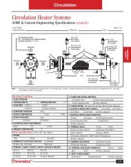
OPTIONAL EQUIPMENT FOR CHROMALOX STEAM BOILERSAUXILIARY LOW WATER CUT-OFF(See page 4 for Wiring Diagram)OperationOperation of this control is accomplished by sensing a minute ACcurrent flowing between submerged contact probe in the boiler shell.When this minute AC current is conducted through an external circuitresistance up to 100,000 ohms or less, a signal of sufficient magnitudeis present to trigger the SCR <strong>and</strong>, in turn, energize the controlrelay.As the water level in the boiler drops below the level of the probe.the AC circuit is broken <strong>and</strong> the control relay is de-energized. The controlwill not energize until sufficient water is present in the boiler.SpecificationsInput supply ....................120 vac/50-60 hzDelectable Range............100.000 ohmsProbe Voltage..................24 vacProbe Current..................10 milliamps<strong>Control</strong> Relay ................Single pole double throwCAUTION: <strong>Control</strong> will not work with de-ionized ordemineralized water.PROPORTIONING PRESSURE CONTROL (See Figure 17)Typical OperationPressure variations cause the bellows to exp<strong>and</strong> or contract.Linkage between the bellows <strong>and</strong> the potentiometer wiper causes thewiper to move across the windings on the potentiometer. This variesthe resistance between R <strong>and</strong> B, <strong>and</strong> between R <strong>and</strong> W, causing animbalance in the circuit connected to the controller.A proportioning pressure control is used to regulate a motor drivenor solid state sequencer. The controller potentiometer, the feedbackpotentiometer in the motor <strong>and</strong> a balancing relay in the motor form anelectric bridge circuit. As long as the pressure of the controlled mediumremains at the set point of the controller, the circuit is balanced;i.e., equal currents flow through both sides of the balancing relay <strong>and</strong>the relay contacts are open. When the circuit is balanced, the motordoes not run.If the pressure of the controlled medium rises, the wiper in the controllermoves toward W. This unbalances the circuit, so a larger currentflows through one side of the balancing relay. The “close” contacts inthe relay make, causing the motor to drive toward its closed position.As the motor runs, the wiper on the feedback potentiometer moves ina direction balance, the balancing relay contacts open <strong>and</strong> the motorstops.Similarly, if the pressure of the controlled medium falls, the wiperon the controller potentiometer moves toward B, <strong>and</strong> the “open” contactsin the balancing relay make. The motor drives toward its openposition until circuit balance is achieved.The slightest change in the pressure of the controlled medium willcause a change in the number of elements energized to compensate forit, thus keeping the pressure constant. This process is called modulation.PROPORTIONAL PRESSURE CONTROL ONLYSUPPLIED WITH SEQUENCERMain Setting - Turn the adjustment screw until the indicator isopposite the low point of the desired throttling range. That is, if thepressure is to be held to a minimum of 50 psi, set the indicator at 50psi. The pressure will then be maintained between 50 psi <strong>and</strong> a higherpressure equal to the 50 psi plus the throttling range.THROTTLING RANGE SETTING L918After setting the indicator for the minimum pressure, turn the throttlingrange adjustment screw until the throttling range indicator pointsto the desired throttling range on the scale. This scale is graduated from“min” to “F”. The value of each division varies with the scale range ofthe instrument.PressureValue EachScale Rating Division on Scale0-15 psi 2.2 psi5-150 psi 3.6 psiPressure scale rating will vary depending on pressure control supplied.CHECKOUTAfter the controller has been installed, wired, <strong>and</strong> set, it should betested with the system in operation. First allow the system to stabilize.Then observe the operation of the controller while raising <strong>and</strong> loweringits set point. Pressure should increase when the set point is raised<strong>and</strong> decrease when the set point is lowered. Use accurate pressure testingequipment when checking out the controller. Do not rely on inexpensivegauges. The controllers are carefully calibrated at the factory.If the motor or actuator runs in the proper direction when the setpoint is adjusted, it can be assumed that the controller is operatingproperly. If it runs in the wrong direction, reverse the B <strong>and</strong> W wires.Observe the action of the motor to see if it stabilizes. If the motor ismoving constantly, widen the proportioning range a little at a time,until the system is stable.Adjusting ScrewDifferentialAdjusting ScrewFigure 17(L91B) Proportioning Pressure <strong>Control</strong> Used with Sequencer <strong>Control</strong>IF A CONTROLLER SEEMSTO OPERATE IMPROPERLY (See Figure 18)If the controller is suspected of operating improperly, it may be furtherchecked as follows.1. Leave the controller installed where it is, but disconnect all powerto the controlled motor.2. Loosen the cover screw below the main scaleplate <strong>and</strong> remove thecover.3. Disconnect the wires from the controller.4. Connect an ohmmeter between controller terminals 8 <strong>and</strong> W tomeasure the resistance of the potentiometer in the controller. Theohmmeter should read about 135 ohms on an L91B.RWB8