CHS Installation Manual - Chromalox Precision Heat and Control
CHS Installation Manual - Chromalox Precision Heat and Control
CHS Installation Manual - Chromalox Precision Heat and Control

Create successful ePaper yourself
Turn your PDF publications into a flip-book with our unique Google optimized e-Paper software.
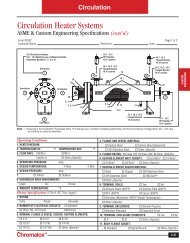
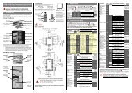
WIRING (cont’d.)Figure 8 – Typical Wiring DiagramToPowerCurcuitRelayPower CircuitTerminal BlockTo Other<strong>Heat</strong>erGroupsElectronic ResistanceSensing Amplifier forAuxiliary Low Water CutoffStepSequencerToOther<strong>Heat</strong>erGroups120 Volt<strong>Control</strong> VoltageHi Limit<strong>Control</strong>Typical 3 Phase <strong>Heat</strong>er GroupLow WaterProbeFigure 9 – Power Circuit DetailFigure 10 – Auxiliary Low Water Cutoff4