CHS Installation Manual - Chromalox Precision Heat and Control
CHS Installation Manual - Chromalox Precision Heat and Control
CHS Installation Manual - Chromalox Precision Heat and Control

Create successful ePaper yourself
Turn your PDF publications into a flip-book with our unique Google optimized e-Paper software.
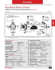
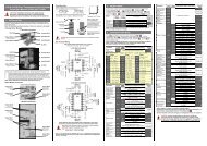
INSTALLATION (cont’d.)SPECIAL INSTRUCTIONS FOR CUSTOMERS SUPPLYINGTHEIR OWN CONDENSATE OR PUMP SYSTEMS.1. Check the voltage of the motor before making the wiring connection.Some <strong>Chromalox</strong> boilers are supplied with dual voltage systems.The motor should always match the voltage of the controlcircuit.2. The motor circuit should be wired into the pump control as shownin wiring diagram.3. A heavy-duty vacuum breaker is required when condensate systemis used. (part number ES-89369)1” CondensateReturnL1” VentStrainers1/2”WaterLineHWidth – 6-1/21” Outletto Boiler1” Drain1/2” Water Line1/2” SolenoidMotor <strong>and</strong>Pump6-5/8”1/2” Strainer 3” 7-1/4”15-1/4” for <strong>CHS</strong>-15016-3/8” for <strong>CHS</strong>-180 to 300Figure 4 – Motor <strong>and</strong> Pump Assembly1” Discharge to Boiler 5-7/8”4-1/4”“W” Dimension – Overall WidthModel Max. Tank Cap.Number PSI (Gal.) L H W<strong>CHS</strong>-150thru 125 33 33-1/4 41-1/2 21<strong>CHS</strong>-300<strong>CHS</strong>-360thru 150 40 40 41-1/2 21<strong>CHS</strong>-420Figure 5 – Condensate Return SystemWIRING1. Wiring to boiler should be as per appropriate wiring diagram suppliedwith boiler <strong>and</strong> in accordance with Local <strong>and</strong> NationalElectrical Codes.2. SAFETY SWITCHES - Purchaser should use a safety switchbetween his main power source <strong>and</strong> the boiler. The safety switchshould use circuit breakers or fuses <strong>and</strong> be in accordance withNEC <strong>and</strong> local codes.Serious thought should be given to the advisability of using a shunttrip safety switch of the circuit breaker type as an additional safetyprecaution. It is possible to utilize the spare contacts in the lowwater cutoff to energize the shunt mechanism on the safety switch.This is an additional safety feature that prevents a dangerous situationshould a contactor or relay stick. Activation of the shunt tripdevice will completely disconnect the boiler from the power supply.(See Figure 7).3. Since boiler heating elements are susceptible to lightning damage,plants not having lightning arresters that have above-ground electricalcable supply sources should install lightning arresters in theproper size to meet the boiler kw load.To Aux.L.W. C.O.Hi-LimitPressuretrolOperatingPressuretrolsTo L2 onTerminal StripCommonSupplyVoltageShunt Trip Device(Supplied by Others)To FieldWiringInputTerminalToL2To MainSwitchL.W.C.O. &Pump <strong>Control</strong>*St<strong>and</strong>ard on <strong>CHS</strong>-150 to <strong>CHS</strong>-300 units in lieu of stepsequencer <strong>and</strong> operating pressuretrol shown in Figure 8To Aux.L.W.C.O.To Motor StarterFigure 6 – Pressuretrol <strong>Control</strong> System*Figure 7 – Safety Switch (Field Installed)3