CHS Installation Manual - Chromalox Precision Heat and Control
CHS Installation Manual - Chromalox Precision Heat and Control
CHS Installation Manual - Chromalox Precision Heat and Control

Create successful ePaper yourself
Turn your PDF publications into a flip-book with our unique Google optimized e-Paper software.
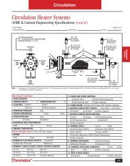
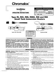
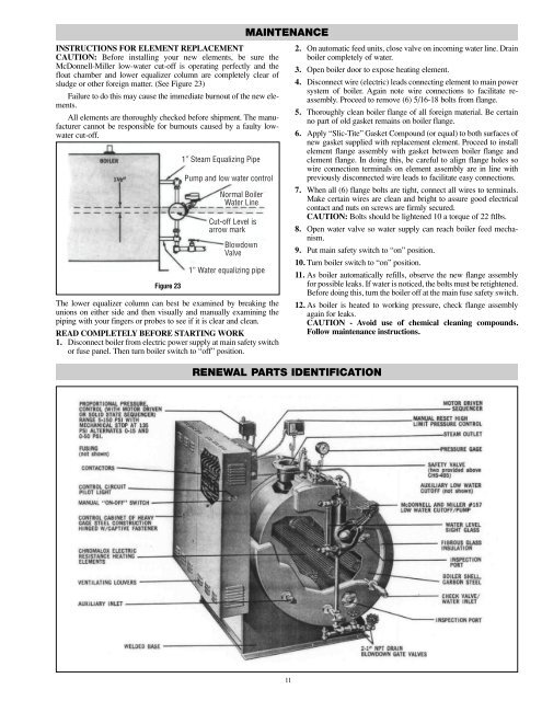
MAINTENANCEINSTRUCTIONS FOR ELEMENT REPLACEMENTCAUTION: Before installing your new elements, be sure theMcDonnell-Miller low-water cut-off is operating perfectly <strong>and</strong> thefloat chamber <strong>and</strong> lower equalizer column are completely clear ofsludge or other foreign matter. (See Figure 23)Failure to do this may cause the immediate burnout of the new elements.All elements are thoroughly checked before shipment. The manufacturercannot be responsible for burnouts caused by a faulty lowwatercut-off.Figure 231” Steam Equalizing PipePump <strong>and</strong> low water controlNormal BoilerWater LineCut-off Level isarrow markBlowdownValve1” Water equalizing pipeThe lower equalizer column can best be examined by breaking theunions on either side <strong>and</strong> then visually <strong>and</strong> manually examining thepiping with your fingers or probes to see if it is clear <strong>and</strong> clean.READ COMPLETELY BEFORE STARTING WORK1. Disconnect boiler from electric power supply at main safety switchor fuse panel. Then turn boiler switch to “off” position.2. On automatic feed units, close valve on incoming water line. Drainboiler completely of water.3. Open boiler door to expose heating element.4. Disconnect wire (electric) leads connecting element to main powersystem of boiler. Again note wire connections to facilitate reassembly.Proceed to remove (6) 5/16-18 bolts from flange.5. Thoroughly clean boiler flange of all foreign material. Be certainno part of old gasket remains on boiler flange.6. Apply “Slic-Tite” Gasket Compound (or equal) to both surfaces ofnew gasket supplied with replacement element. Proceed to installelement flange assembly with gasket between boiler flange <strong>and</strong>clement flange. In doing this, be careful to align flange holes sowire connection terminals on element assembly are in line withpreviously disconnected wire leads to facilitate easy connections.7. When all (6) flange bolts are tight, connect all wires to terminals.Make certain wires are clean <strong>and</strong> bright to assure good electricalcontact <strong>and</strong> nuts on screws are firmly secured.CAUTION: Bolts should be lightened 10 a torque of 22 ftlbs.8. Open water valve so water supply can reach boiler feed mechanism.9. Put main safety switch to “on” position.10. Turn boiler switch to “on” position.11. As boiler automatically refills, observe the new flange assemblyfor possible leaks. If water is noticed, the bolts must be retightened.Before doing this, turn the boiler off at the main fuse safety switch.12. As boiler is heated to working pressure, check flange assemblyagain for leaks.CAUTION - Avoid use of chemical cleaning compounds.Follow maintenance instructions.RENEWAL PARTS IDENTIFICATION11