CHS Installation Manual - Chromalox Precision Heat and Control
CHS Installation Manual - Chromalox Precision Heat and Control
CHS Installation Manual - Chromalox Precision Heat and Control

Create successful ePaper yourself
Turn your PDF publications into a flip-book with our unique Google optimized e-Paper software.
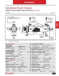
INSTALLATION (cont’d.)High Pressure<strong>Control</strong>Step Sequencer(Optional)<strong>Heat</strong>ingElementsReturnInlet (J)PressureGauge<strong>Manual</strong> ResetPressure ConrolAElectric<strong>Control</strong>Box30”WaterLevel<strong>Control</strong>EGHISafetyValve (G) SteamOutlet (F)Blow DownDrain Valve (L)60”Blow DownDrain Valve(L)CBWallCheck ValveWater Inlet (K)DWallFigure 1 Figure 2 Figure 3*<strong>CHS</strong>- thru 1620 have 2 control boxes (See Figure 2). Add 13” to “B” dimension.Model Number A B C D E F* G H I J K L<strong>CHS</strong>-150 thru <strong>CHS</strong>-300 57” 45” 32” 40” 68” 3” NPT 1” 25” 31” 2” NPT 1” NPT 1” NPT<strong>CHS</strong>-360 thru <strong>CHS</strong>-420 57” 45” 32” 40” 68” 4” 1” 25” 31” 2” NPT 1” NPT 1” NPT<strong>CHS</strong>-495 thru <strong>CHS</strong>-630 57” 45” 32” 47” 86” 4” 1” 34” 40” 2” NPT 1” NPT 1” NPT<strong>CHS</strong>-720 thru <strong>CHS</strong>-810 76” 58” 45” 47” 94” 6” 1-1/2” 38” 44” 2” NPT 1” NPT 1” NPT<strong>CHS</strong>-945 thru <strong>CHS</strong>-1080 76” 68” 45” 47” 94” 6” 1-1/2” 38” 44” 2” NPT 1” NPT 1” NPT<strong>CHS</strong>-1215 thru <strong>CHS</strong>-1620 86” 76” 56” 50” 98” 6” 1-1/2” 40” 46” 2” NPT 1-1/2” NPT 1” NPT*4” <strong>and</strong> 6” are flanged.Typical Plumbing <strong>Installation</strong> of a Steam Boiler with Condensate Return SystemSafetyValveGlobeValveInsulated Steam Lines(Pitch Down 5˚)Water/SteamSeparatorGateValve<strong>Heat</strong>ExchangerGateValve(Typical Load)VacuumBreakerCheckValveTrapTrapCheck ValveCheck ValveReturnDrainBoilerAuxiliaryInletCold Water(for Initial Fill)Pitch Down 5˚CondensateReturnVentCold WaterMake-UpDrainStrainerCentrifugalTurbine Pump2
INSTALLATION (cont’d.)SPECIAL INSTRUCTIONS FOR CUSTOMERS SUPPLYINGTHEIR OWN CONDENSATE OR PUMP SYSTEMS.1. Check the voltage of the motor before making the wiring connection.Some <strong>Chromalox</strong> boilers are supplied with dual voltage systems.The motor should always match the voltage of the controlcircuit.2. The motor circuit should be wired into the pump control as shownin wiring diagram.3. A heavy-duty vacuum breaker is required when condensate systemis used. (part number ES-89369)1” CondensateReturnL1” VentStrainers1/2”WaterLineHWidth – 6-1/21” Outletto Boiler1” Drain1/2” Water Line1/2” SolenoidMotor <strong>and</strong>Pump6-5/8”1/2” Strainer 3” 7-1/4”15-1/4” for <strong>CHS</strong>-15016-3/8” for <strong>CHS</strong>-180 to 300Figure 4 – Motor <strong>and</strong> Pump Assembly1” Discharge to Boiler 5-7/8”4-1/4”“W” Dimension – Overall WidthModel Max. Tank Cap.Number PSI (Gal.) L H W<strong>CHS</strong>-150thru 125 33 33-1/4 41-1/2 21<strong>CHS</strong>-300<strong>CHS</strong>-360thru 150 40 40 41-1/2 21<strong>CHS</strong>-420Figure 5 – Condensate Return SystemWIRING1. Wiring to boiler should be as per appropriate wiring diagram suppliedwith boiler <strong>and</strong> in accordance with Local <strong>and</strong> NationalElectrical Codes.2. SAFETY SWITCHES - Purchaser should use a safety switchbetween his main power source <strong>and</strong> the boiler. The safety switchshould use circuit breakers or fuses <strong>and</strong> be in accordance withNEC <strong>and</strong> local codes.Serious thought should be given to the advisability of using a shunttrip safety switch of the circuit breaker type as an additional safetyprecaution. It is possible to utilize the spare contacts in the lowwater cutoff to energize the shunt mechanism on the safety switch.This is an additional safety feature that prevents a dangerous situationshould a contactor or relay stick. Activation of the shunt tripdevice will completely disconnect the boiler from the power supply.(See Figure 7).3. Since boiler heating elements are susceptible to lightning damage,plants not having lightning arresters that have above-ground electricalcable supply sources should install lightning arresters in theproper size to meet the boiler kw load.To Aux.L.W. C.O.Hi-LimitPressuretrolOperatingPressuretrolsTo L2 onTerminal StripCommonSupplyVoltageShunt Trip Device(Supplied by Others)To FieldWiringInputTerminalToL2To MainSwitchL.W.C.O. &Pump <strong>Control</strong>*St<strong>and</strong>ard on <strong>CHS</strong>-150 to <strong>CHS</strong>-300 units in lieu of stepsequencer <strong>and</strong> operating pressuretrol shown in Figure 8To Aux.L.W.C.O.To Motor StarterFigure 6 – Pressuretrol <strong>Control</strong> System*Figure 7 – Safety Switch (Field Installed)3
WIRING (cont’d.)Figure 8 – Typical Wiring DiagramToPowerCurcuitRelayPower CircuitTerminal BlockTo Other<strong>Heat</strong>erGroupsElectronic ResistanceSensing Amplifier forAuxiliary Low Water CutoffStepSequencerToOther<strong>Heat</strong>erGroups120 Volt<strong>Control</strong> VoltageHi Limit<strong>Control</strong>Typical 3 Phase <strong>Heat</strong>er GroupLow WaterProbeFigure 9 – Power Circuit DetailFigure 10 – Auxiliary Low Water Cutoff4
OPERATION (cont’d.)Now turn the wheel on the large timer until the “off” tab passes the“time now” arrow. The “boiler normal” light should go out <strong>and</strong> thevalve should begin to open. Once the “valve open” light goes on, thevalve should remain open for a few seconds <strong>and</strong> then automaticallyclose. The “drain valve closed” light should light <strong>and</strong> the “boiler normal”light should remain off.NORMAL OPERATION – Set the “Boiler Normal/24-hour duty”switch located on the inside of the control panel to “boiler normal” ifthe boiler is to be shut down each night. Set it to “24-hour duty” if theboiler is to remain on continuously 24 hours per day (except duringblowdown).Set the tabs on the large timer for the ON <strong>and</strong> OFF times desiredfor the boiler, screw in the small black day-skip tabs if the boiler is toremain off for the weekend, etc.If the boiler is on 24-hour duty set the OFF tab for the time that isdesired for blowdown. The ON tab can be ignored, but must remain ontimer.The small time delay relay controls the time that the drain valveremains open. Counterclockwise decreases, clockwise increases blowdowntime. Time must be adjusted by trial.Figure 16 – Typical Wiring for Automatic Blowdown System7
OPTIONAL EQUIPMENT FOR CHROMALOX STEAM BOILERSAUXILIARY LOW WATER CUT-OFF(See page 4 for Wiring Diagram)OperationOperation of this control is accomplished by sensing a minute ACcurrent flowing between submerged contact probe in the boiler shell.When this minute AC current is conducted through an external circuitresistance up to 100,000 ohms or less, a signal of sufficient magnitudeis present to trigger the SCR <strong>and</strong>, in turn, energize the controlrelay.As the water level in the boiler drops below the level of the probe.the AC circuit is broken <strong>and</strong> the control relay is de-energized. The controlwill not energize until sufficient water is present in the boiler.SpecificationsInput supply ....................120 vac/50-60 hzDelectable Range............100.000 ohmsProbe Voltage..................24 vacProbe Current..................10 milliamps<strong>Control</strong> Relay ................Single pole double throwCAUTION: <strong>Control</strong> will not work with de-ionized ordemineralized water.PROPORTIONING PRESSURE CONTROL (See Figure 17)Typical OperationPressure variations cause the bellows to exp<strong>and</strong> or contract.Linkage between the bellows <strong>and</strong> the potentiometer wiper causes thewiper to move across the windings on the potentiometer. This variesthe resistance between R <strong>and</strong> B, <strong>and</strong> between R <strong>and</strong> W, causing animbalance in the circuit connected to the controller.A proportioning pressure control is used to regulate a motor drivenor solid state sequencer. The controller potentiometer, the feedbackpotentiometer in the motor <strong>and</strong> a balancing relay in the motor form anelectric bridge circuit. As long as the pressure of the controlled mediumremains at the set point of the controller, the circuit is balanced;i.e., equal currents flow through both sides of the balancing relay <strong>and</strong>the relay contacts are open. When the circuit is balanced, the motordoes not run.If the pressure of the controlled medium rises, the wiper in the controllermoves toward W. This unbalances the circuit, so a larger currentflows through one side of the balancing relay. The “close” contacts inthe relay make, causing the motor to drive toward its closed position.As the motor runs, the wiper on the feedback potentiometer moves ina direction balance, the balancing relay contacts open <strong>and</strong> the motorstops.Similarly, if the pressure of the controlled medium falls, the wiperon the controller potentiometer moves toward B, <strong>and</strong> the “open” contactsin the balancing relay make. The motor drives toward its openposition until circuit balance is achieved.The slightest change in the pressure of the controlled medium willcause a change in the number of elements energized to compensate forit, thus keeping the pressure constant. This process is called modulation.PROPORTIONAL PRESSURE CONTROL ONLYSUPPLIED WITH SEQUENCERMain Setting - Turn the adjustment screw until the indicator isopposite the low point of the desired throttling range. That is, if thepressure is to be held to a minimum of 50 psi, set the indicator at 50psi. The pressure will then be maintained between 50 psi <strong>and</strong> a higherpressure equal to the 50 psi plus the throttling range.THROTTLING RANGE SETTING L918After setting the indicator for the minimum pressure, turn the throttlingrange adjustment screw until the throttling range indicator pointsto the desired throttling range on the scale. This scale is graduated from“min” to “F”. The value of each division varies with the scale range ofthe instrument.PressureValue EachScale Rating Division on Scale0-15 psi 2.2 psi5-150 psi 3.6 psiPressure scale rating will vary depending on pressure control supplied.CHECKOUTAfter the controller has been installed, wired, <strong>and</strong> set, it should betested with the system in operation. First allow the system to stabilize.Then observe the operation of the controller while raising <strong>and</strong> loweringits set point. Pressure should increase when the set point is raised<strong>and</strong> decrease when the set point is lowered. Use accurate pressure testingequipment when checking out the controller. Do not rely on inexpensivegauges. The controllers are carefully calibrated at the factory.If the motor or actuator runs in the proper direction when the setpoint is adjusted, it can be assumed that the controller is operatingproperly. If it runs in the wrong direction, reverse the B <strong>and</strong> W wires.Observe the action of the motor to see if it stabilizes. If the motor ismoving constantly, widen the proportioning range a little at a time,until the system is stable.Adjusting ScrewDifferentialAdjusting ScrewFigure 17(L91B) Proportioning Pressure <strong>Control</strong> Used with Sequencer <strong>Control</strong>IF A CONTROLLER SEEMSTO OPERATE IMPROPERLY (See Figure 18)If the controller is suspected of operating improperly, it may be furtherchecked as follows.1. Leave the controller installed where it is, but disconnect all powerto the controlled motor.2. Loosen the cover screw below the main scaleplate <strong>and</strong> remove thecover.3. Disconnect the wires from the controller.4. Connect an ohmmeter between controller terminals 8 <strong>and</strong> W tomeasure the resistance of the potentiometer in the controller. Theohmmeter should read about 135 ohms on an L91B.RWB8
OPTIONAL EQUIPMENT FOR CHROMALOX STEAM BOILERS (cont’d.)5. Connect the ohmmeter between controller terminals W <strong>and</strong> R <strong>and</strong>raise the set point of the controller above the actual pressure beingmeasured. The ohmmeter should read the full value of the potentiometermeasured in step 4 (135 ohms for an L91B).6. Slowly lower the set point of the controller while observing theohmmeter reading. The resistance should drop to zero at some setpoint below the actual pressure.7. An approximation of the proportioning range can be made byobserving the change in set point required for a resistance changefrom zero to full value.8. When the controller is operating properly, reconnect the wires,replace the cover. tighten the cover screw, <strong>and</strong> reset the controllerto the desired value.9. Reconnect power to the controlled motor.TESTING OPERATION OF SEQUENCER (See Figure 20)1. With boiler off, remove wiring from pressure control on sequencerlow voltage terminal board.2. Turn on boiler to supply the voltage to sequencer. Short terminal R<strong>and</strong> B for counter-clockwise rotation <strong>and</strong> terminal R <strong>and</strong> W forclockwise rotation.3. If sequencer operates under this test procedure, but when rewiredto pressure controller, does not function, check pressure control.Note that wiring is W-B <strong>and</strong> B-W-R-R between sequencer <strong>and</strong>pressure control.Main ScaleAdjusting ScrewProportioning RangeAdjusting ScrewMain ScaleSettingIndicatorRWBOhmmeterSetpointWR BIncreasesto 15 OhmsNote: Terminals are not labeled, but screw-heads arecolor-coded red (R), white (W) <strong>and</strong> blue (B).Figure 18BOILER SEQUENCER (5 STEP)RECYCLE FEATURE (See Figure 19)The step control is designed to drop out all contactors when controlcircuit is interrupted. On resumption of power, the camshaft rotatesto the counter-clockwise (ccw) limit, opening all the load switches.The recycle relay then energizes, pulling in the load contact, <strong>and</strong> finallythe camshaft rotates clockwise (cw) to the position called for by thepressure controller energizing, in sequence, the required load stages.Figure 20Typical Wiring Diagram for 5 Step Motor Driven SequencerSEQUENCE REVERSER (See Figure 21)GENERAL:Sequence Reverser is an automatic switching device which isinterposed on an electric boiler between the proportional sequencecontroller <strong>and</strong> the heating element contactors. The device is periodicallyactuated to alter the operating sequence of each of the heatingelements, thereby increasing the overall reliability of the boiler.DETAILS:The Sequence Reverser consists of an eight-day timer set up forfour days on <strong>and</strong> four days off which energizes <strong>and</strong> de-energizes doublethrow relays which are wired to reverse the “firing” order of theheating element contactors with each operation of the timer.Figure 19 – Five Step Sequencer9
OPTIONAL EQUIPMENT FOR CHROMALOX STEAM BOILERS (cont’d.)The Sequence Reverser accomplishes its tasks <strong>and</strong> shows the relativeuse of each of ten beat stages during the first four days of thecycle. This is how the work load would be distributed on a boiler withoutSequence Reverser. It can be seen the early stages are ON most ofthe time <strong>and</strong> the later stages are OFF most of the time, since they areused only during heat load peaks. (This analysis assumes hours of usedirectly affecting component life. Frequency of on/off operations hasbeen ignored because of the limited in-rush associated with beatingelements <strong>and</strong> because of the relative independence of contactor life onnumber of operations in the resistive load situations.)It is clear, without sequence reversing, the early stages would tendto fail long before the later stages. The sequence reverser essentiallyequalizes the relative usages of heating stages. It can be seen, withoutthe sequence reverser the first heat stage is used approximately twiceas much as it is with the sequence reverser. This means the boiler willbe likely to have its first element failure in half the time withoutSolid State Progressive Sequencer (See Figure 22)The solid state progressive sequencer provides accurate electroniccontrol of multi-stage loads of the type used in <strong>Chromalox</strong> steam boilers.It features progressive sequencing (first on-first off) which equalizesthe operating time of each load. This control gives visual indicationof each energized stage by means of integral solid state light emittingdiodes. In the event of power interruption all heating elements areimmediately de-energized for safety. When power resumes, the controlwill re-stage the loads one at a time. Refer to the diagram for visualdescription of progressive sequencing.PROGRESSIVE SEQUENCINGThe solid state sequencer operates on 120 V AC/60 Hz <strong>and</strong> eachoutput is relay switched with a load rating of 125 VA at 120 VAC.Figure 21 – Five Step Sequence Reversersequence reverser as compared to the boiler with sequence reverser. Inaddition. boilers without sequence reverser will have many failuresspread over a long time while boilers with sequence reversing willrequire element changes at roughly the same time. (See wiring diagramon Page 4).Figure 22 – Solid State SequencerMAINTENANCECAUTION: Hazard of electric shock. Disconnect allpower before working on boiler.<strong>Chromalox</strong> Electric Steam Boilers are designed for years of trouble-freeperformance. To establish a good preventative maintenanceprogram, we suggest the building maintenance man or engineer familiarizehimself with these simple rules:1. The use of specific boiler cleaning compounds cannot be recommended.We do recommend that a reputable firm of water treatmentengineers be consulted regarding conditioning boiler water.Proper selection must be made of a compound to prevent damageto copper sheath heating elements.2. The sight glass should be checked daily to ensure the boiler hasadequate water.3. A monthly inspection should be made of the internal wiring. Allelectrical connections should be checked for lightness.4. A check for water or steam leaks should also be made <strong>and</strong> anyloose fittings immediately tightened.5. If boiler is equipped with a Solid State Auxiliary Low WaterCutoff, every four months the probe should be checked fordeposits <strong>and</strong> cleaned, if necessary. This is accomplished by removingthe inspection plate, removing the probe (with a st<strong>and</strong>ardsparkplug wrench) cleaning <strong>and</strong> replacing.Note: The system will not operate if the boiler is using distilled,demineralized or deionized water.At the same time, one of the bottom heating elements should beremoved. If scale has begun to form, all elements should becleaned <strong>and</strong> boiler drained <strong>and</strong> flushed.6. IMPORTANT: The Manufacturers' Data Report enclosed withinthe instruction sheet is very important <strong>and</strong> must be put in a safeplace. You may be called upon to produce it by a State agency.10
MAINTENANCEINSTRUCTIONS FOR ELEMENT REPLACEMENTCAUTION: Before installing your new elements, be sure theMcDonnell-Miller low-water cut-off is operating perfectly <strong>and</strong> thefloat chamber <strong>and</strong> lower equalizer column are completely clear ofsludge or other foreign matter. (See Figure 23)Failure to do this may cause the immediate burnout of the new elements.All elements are thoroughly checked before shipment. The manufacturercannot be responsible for burnouts caused by a faulty lowwatercut-off.Figure 231” Steam Equalizing PipePump <strong>and</strong> low water controlNormal BoilerWater LineCut-off Level isarrow markBlowdownValve1” Water equalizing pipeThe lower equalizer column can best be examined by breaking theunions on either side <strong>and</strong> then visually <strong>and</strong> manually examining thepiping with your fingers or probes to see if it is clear <strong>and</strong> clean.READ COMPLETELY BEFORE STARTING WORK1. Disconnect boiler from electric power supply at main safety switchor fuse panel. Then turn boiler switch to “off” position.2. On automatic feed units, close valve on incoming water line. Drainboiler completely of water.3. Open boiler door to expose heating element.4. Disconnect wire (electric) leads connecting element to main powersystem of boiler. Again note wire connections to facilitate reassembly.Proceed to remove (6) 5/16-18 bolts from flange.5. Thoroughly clean boiler flange of all foreign material. Be certainno part of old gasket remains on boiler flange.6. Apply “Slic-Tite” Gasket Compound (or equal) to both surfaces ofnew gasket supplied with replacement element. Proceed to installelement flange assembly with gasket between boiler flange <strong>and</strong>clement flange. In doing this, be careful to align flange holes sowire connection terminals on element assembly are in line withpreviously disconnected wire leads to facilitate easy connections.7. When all (6) flange bolts are tight, connect all wires to terminals.Make certain wires are clean <strong>and</strong> bright to assure good electricalcontact <strong>and</strong> nuts on screws are firmly secured.CAUTION: Bolts should be lightened 10 a torque of 22 ftlbs.8. Open water valve so water supply can reach boiler feed mechanism.9. Put main safety switch to “on” position.10. Turn boiler switch to “on” position.11. As boiler automatically refills, observe the new flange assemblyfor possible leaks. If water is noticed, the bolts must be retightened.Before doing this, turn the boiler off at the main fuse safety switch.12. As boiler is heated to working pressure, check flange assemblyagain for leaks.CAUTION - Avoid use of chemical cleaning compounds.Follow maintenance instructions.RENEWAL PARTS IDENTIFICATION11
RENEWAL PARTS IDENTIFICATION (cont’d.)Bellows BaseClamp AssemblyBellows Assemblywith GasketAUTOMATIC FEED PUMP CONTROLLERJunction Panel3 WireSwitch2 WireSwitchBellows Base Clamp<strong>and</strong> Bellows AssemblyLow Water Cutoff <strong>and</strong> Water Feed <strong>Control</strong>sDescriptionPart NumberComplete Assembly . . . . . . . . . . . . . . . . . . . . . . . . . . . . . . . . . . . . . 300-118538-013Complete Assembly (<strong>Manual</strong> Reset) . . . . . . . . . . . . . . . . . . . . . . . . 300-118538-026Complete Head Mechanism . . . . . . . . . . . . . . . . . . . . . . . . . . . . . . . 300-118538-027Complete Head Mechanism (<strong>Manual</strong> Reset) . . . . . . . . . . . . . . . . . . 300-118538-028Float <strong>and</strong> Rod . . . . . . . . . . . . . . . . . . . . . . . . . . . . . . . . . . . . . . . . . . 300-118538-029Head Gasket . . . . . . . . . . . . . . . . . . . . . . . . . . . . . . . . . . . . . . . . . . . 300-118538-0303 Wire Cut-Off <strong>and</strong> Alarm Switch . . . . . . . . . . . . . . . . . . . . . . . . . . . 292-118665-0033 Wire Cut-off <strong>and</strong> Alarm Switch (<strong>Manual</strong> Reset) . . . . . . . . . . . . . . 292-118665-0042 Wire Pump Switch . . . . . . . . . . . . . . . . . . . . . . . . . . . . . . . . . . . . . 292-118665-002Junction Panel . . . . . . . . . . . . . . . . . . . . . . . . . . . . . . . . . . . . . . . . . . 300-118538-031Bellows Base Clamp & Bellows Assembly . . . . . . . . . . . . . . . . . . . . 300-118538-032Bellows Base Clamp & Bellows Assembly (<strong>Manual</strong> Reset) . . . . . . . 300-118538-033Bellows Base Gasket . . . . . . . . . . . . . . . . . . . . . . . . . . . . . . . . . . . . . 300-118538-034Bellows Base Clamp Assembly . . . . . . . . . . . . . . . . . . . . . . . . . . . . . 300-118538-035Bellows Base Clamp Assembly (<strong>Manual</strong> Reset) . . . . . . . . . . . . . . . . 300-118538-036Bellows Assembly w/Gasket . . . . . . . . . . . . . . . . . . . . . . . . . . . . . . . 300-118538-037B-W Auxiliary Low Water Cut-off . . . . . . . . . . . . . . . . . . . . . . . . . . . 300-118538-038<strong>Heat</strong>ing Elements <strong>and</strong> GasketsDescriptionPart Number30kW, 3 ph, 240V . . . . . . . . . . . . . . . . . . . . . . . . . . . . . . . . . . . . . . . 155-118524-04030kW, 3 ph, 480V . . . . . . . . . . . . . . . . . . . . . . . . . . . . . . . . . . . . . . . 155-118524-02145kW, 3 ph, 480V . . . . . . . . . . . . . . . . . . . . . . . . . . . . . . . . . . . . . . . 155-118524-04145kW, 3 ph, 240V . . . . . . . . . . . . . . . . . . . . . . . . . . . . . . . . . . . . . . . 155-118524-04260kW, 3 ph, 240V . . . . . . . . . . . . . . . . . . . . . . . . . . . . . . . . . . . . . . . 155-118524-02660kW, 3 ph, 480V . . . . . . . . . . . . . . . . . . . . . . . . . . . . . . . . . . . . . . . 155-118524-02290kW, 3 ph, 480V . . . . . . . . . . . . . . . . . . . . . . . . . . . . . . . . . . . . . . . 155-118524-023135kW, 3 ph, 480V . . . . . . . . . . . . . . . . . . . . . . . . . . . . . . . . . . . . . . 155-118524-043Element Gasket . . . . . . . . . . . . . . . . . . . . . . . . . . . . . . . . . . . . . . . . . 132-146012-002H<strong>and</strong> Hole Gasket . . . . . . . . . . . . . . . . . . . . . . . . . . . . . . . . . . . . . . . 132-118533-004Contactors <strong>and</strong> Contactor PartsDescriptionPart NumberContactor (50 amp, 115V, 60 cy.) . . . . . . . . . . . . . . . . . . . . . . . . . . . 072-118525-001Contactor (50 amp, 240V, 60 cy.) . . . . . . . . . . . . . . . . . . . . . . . . . . . 072-118525-002Contactor (60 amp, 115V) . . . . . . . . . . . . . . . . . . . . . . . . . . . . . . . . 072-118525-003Contactor (75 amp, 115V, 60 cy.) . . . . . . . . . . . . . . . . . . . . . . . . . . . 072-118525-005Contactor (75 amp, 208/240V, 60 cy.) . . . . . . . . . . . . . . . . . . . . . . . 072-118525-006Relay PR 7AY, 115V . . . . . . . . . . . . . . . . . . . . . . . . . . . . . . . . . . . . . 072-118525-008Relay PR 7AY, 230V . . . . . . . . . . . . . . . . . . . . . . . . . . . . . . . . . . . . . 072-118525-009Terminal Blocks <strong>and</strong> FusesDescriptionPart Number<strong>Control</strong> Circuit Fuse <strong>and</strong> Block . . . . . . . . . . . . . . . . . . . . . . . . . . . . . 129-118527-001Fuse Block, Class “J” 100 amp . . . . . . . . . . . . . . . . . . . . . . . . . . . . . 129-118527-003Power Circuit Fuse, Class “J” 60 amp. . . . . . . . . . . . . . . . . . . . . . . . 128-118530-003Power Circuit Fuse, Class “J” 100 amp. . . . . . . . . . . . . . . . . . . . . . . 128-118530-004Valves <strong>and</strong> GaugesDescriptionPart NumberPressure Gauge 3-1/2, 160# . . . . . . . . . . . . . . . . . . . . . . . . . . . . . . . 344-118529-024Gauge Glass Assembly . . . . . . . . . . . . . . . . . . . . . . . . . . . . . . . . . . . 347-118537-002Sight Glass . . . . . . . . . . . . . . . . . . . . . . . . . . . . . . . . . . . . . . . . . . . . 374-118537-009Safety Valve – 30#, 1” . . . . . . . . . . . . . . . . . . . . . . . . . . . . . . . . . . . . 344-118529-006Safety Valve – 125#, 1” . . . . . . . . . . . . . . . . . . . . . . . . . . . . . . . . . . . 344-118529-020Safety Valve – 150#, 1” . . . . . . . . . . . . . . . . . . . . . . . . . . . . . . . . . . . 344-118529-025Check Valve – 1” Spring Type . . . . . . . . . . . . . . . . . . . . . . . . . . . . . . 276-118536-003Safety Valve – 15#, 1 . . . . . . . . . . . . . . . . . . . . . . . . . . . . . . . . . . . . 344-118529-008Float <strong>and</strong> RodHead GasketSylphon BellowAssembly(See picture)Bellows Base GasketCondensate Return SystemsDescriptionPart NumberCondensate Return System (Comp.) 1/2 H.P.115V or 230V, 60 cy. (<strong>CHS</strong>-150) . . . . . . . . . . . . . . . . . . . . . . . . . . 226-118656-002Condensate Return System (Comp.) 3/4 H.P.115V or 230V, 60 cy. (<strong>CHS</strong>-180 to <strong>CHS</strong>-300) . . . . . . . . . . . . . . . . 226-118656-009(For Boilers <strong>CHS</strong>-360 through <strong>CHS</strong>-1350 check factory)Pressure <strong>Control</strong>s <strong>and</strong> SequencersDescriptionPart NumberPressure <strong>Control</strong> Complete . . . . . . . . . . . . . . . . . . . . . . . . . . . . . . . . 344-118529-010Pressure <strong>Control</strong> Complete (<strong>Manual</strong> Reset) . . . . . . . . . . . . . . . . . . . 344-118529-011Mercury Tube (Two Wire) . . . . . . . . . . . . . . . . . . . . . . . . . . . . . . . . . 292-118665-001Pressure <strong>Control</strong> Type L91B, 0-150 . . . . . . . . . . . . . . . . . . . . . . . . . 344-118529-0155 Step Proportional Sequencer . . . . . . . . . . . . . . . . . . . . . . . . . . . . . 300-118538-00510 Step Proportional Sequencer . . . . . . . . . . . . . . . . . . . . . . . . . . . . 300-118538-008Pressure COntrol Type L91B, 0-15 . . . . . . . . . . . . . . . . . . . . . . . . . . 334-118529-016Parts for Condensate Systems – Hot Water Motors & PumpsDescriptionPart NumberImpeller for Pump (192 or 3/4 H.P). . . . . . . . . . . . . . . . . . . . . . . . . 266-118671-001Parts for Condensate Return SystemsDescriptionPart NumberPumps <strong>and</strong> Motor, 1/2 H.P., 115 Volts or230 Volts, 1 ph. (<strong>CHS</strong>-150) . . . . . . . . . . . . . . . . . . . . . . . . . . . . . . 226-118656-005Pump <strong>and</strong> Motor 3/4 H.P., 115 Volts or230 Volts, 1 ph. (<strong>CHS</strong>-180 to 300) . . . . . . . . . . . . . . . . . . . . . . 226-118656-006Float Valve – 33 Gallon Tank (<strong>CHS</strong>-150 to 300 . . . . . . . . . . . . . . . . 226-118662-006Seal for Pump (<strong>CHS</strong>-150 to 300) . . . . . . . . . . . . . . . . . . . . . . . . . . . 251-118657-002(For Boilers <strong>CHS</strong>-360 through <strong>CHS</strong>-1350 check factory)Vacuum Breaker . . . . . . . . . . . . . . . . . . . . . . . . . . . . . . . . . . . . . . . . 300-118538-039Limited Warranty:Please refer to the <strong>Chromalox</strong> limited warranty applicable to this product athttp://www.chromalox.com/customer-service/policies/termsofsale.aspx.2150 N. RULON WHITE BLVD., OGDEN, UT 84404Phone: 1-800-368-2493 www.chromalox.com