You also want an ePaper? Increase the reach of your titles
YUMPU automatically turns print PDFs into web optimized ePapers that Google loves.
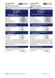
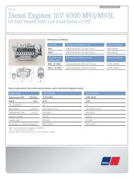
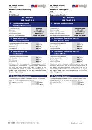
TB 46204 f 50OAGD - 14.10.2011Technical DescriptionGBGenset without heat recovery boxAoE 12V4000L621 Ratings and EmissionsFor operation onNATURAL GASMethane numberMZ ≥ 70Low heat value (LHV)Hu = 8,0-11,5 kWh/m³nCooling water temperature90 / 78 °CGenset with synchronous generatorfor generating3Ph, 50HzGas mixture cooler, intern(1 st stage HT)integratedGas mixture cooler, extern(2 nd stage LT)40 °CNO x < 500 < 2501.1 Continuous Operating Data in Grid Parallel Modemg/m n38 % tolerance for thermal outputs and 5 % for total energy input listed. Performance data in accordance with ISO 3046. All data apply to gridparallel operation. Data for site operating conditions other than those mentioned, available on demand. Max. reactive power in kVA, resp. nominalcurrent acc. to nominal output of the generator.Grid parallelmode, onlyGrid parallel- and isolated modeGenerator voltageElectrical output of generator(no overload capacity)Thermal output(Engine cooling / lube oil / 1 st stage HT mixture cooler)Thermal output(2 nd stage LT mixture cooling)Total energy input1.2Generator voltageElectrical output of generatorGB1165N5 GB1168N5 GB1166N5Part Load Data in Grid Parallel Mode (75 %)Thermal output(Engine cooling / lube oil / 1 st stage HT mixture cooler)Thermal output(2 nd stage LT mixture cooling)Total energy input1.3GB1165N5GB1165N5400 415 400 415 6300 10500 11000 V1165 1165 1168 1168 1166 1165 1165 kW elkW thkW th400 415 400 415 6300 10500 11000 V874 874 873 873 871 871 871 kW elGenerator voltage 400 415 400 415 6300 10500 11000 VElectrical output of generator580 580 578 578 576 575 575 kW elThermal output(Engine cooling / lube oil / 1 st stage HT mixture cooler)352 352kW thGenerator voltage 400 415 400 415 6300 10500 11000 VElectrical output of generator 1060 1060 1059 1058 1058 kW el490Part Load Data in Grid Parallel Mode (50 %)660 6872822575042169 2239Thermal output(2 nd stage LT mixture cooling)4643Total energy input 1539 15711.4 Continuous Operating Data in Isolated Mode7781292661kWkW thkW thkWkW thkWAoE 12V4000L62 /1500/12,8:1/70/9078/omKat/500 250/TVU 2010-09-10 / TA 733517e 733516e / TVU 2010-09-13 / 1/2TA 733903e 733902e Seite/Sheet 1 von/of 7
TB 46204 f 50OAGD - 14.10.2011Technical DescriptionGB1.5Pollutant EmissionsEmission values related to dry exhaust gas with 5 % O 2 . (For exhaust gas volume flow see 3.5)NO x , stated as NO 2 < 500< 250CO, without catalyst< 1000Formaldehyde, without catalyst< 140 < 155CO, with catalyst(optional, delivered loose)< 300Formaldehyde, with catalyst(optional, delivered loose)< 602 Design Principles / Scope of Supply••••mg/m n3mg/m n3mg/m n3mg/m n3mg/m n3Engine and flange-mounted alternator (SAE 00 housing) are connected via a torsionally resilient coupling and resiliently mounted to arigid, welded steel base frame.Standby heaterLube oil pump for draining the oil sump (incl. two solenoid valves).The base frame is installed on vibration dampers2.1 Engine plus AccessoriesOtto-Gas-EngineMTU 12V4000L62Cyl. arrangement, no. of cyl.V 12Bore / stroke 170 / 210Volume57,20Speed 1500Mean piston speed 10,5Compression ratio12,8:1Mean effective pressure16,8Standard power acc. to ISO 3046, (no overload capacity) 1200mmLitre1/minm/sbarkW mechSpecific full-load consumption (tolerance 5 %)2,35 2,44Gas consumption (based on LHV = 10,03 kWh/m 3 n)281,4 291,7Lube oil consumption(not guaranteed, at rated load and after 1000 Oh)0,3Basic Engine••••Monobloc grey cast crankcase with inspection ports, flywheel housing SAE 00, flywheel 21“ cast iron oil panForged crankshaftForged connecting rodsFour-valve, individual cylinder heads with central pre-chamber armoured valves with „Rotocap“ rotatorskWh/kWh mechm 3 /hg/kWh mech• Light-metal solid-skirt pistons with oil cooling duct, piston cooling via oil spray nozzlesMixture Formation• Air intake via dry-type engine-mounted air filters• Venturi type air-gas mixer with gas supply via electronically controlled gas metering valveTurbocharging• Turbocharger for gas-air mixture compression• Two-stage mixture cooling• Throttles between mixture coolers and intake manifoldExhaust System• Dry-type, insulated exhaust manifolds in the engine VeeLube Oil System• Lube oil circulation pump with safety valve for forced-feed lubrication and piston cooling• Engine mounted heat exchanger• Lube oil filters with replaceable filter elements• Engine-mounted device for automatic oil level control• Oil dipstick• Closed crankcase venting system with oil separator connected to mixture piping before turbo charger• Connections for oil refill and oil drainingCooling System (2-circuit)• High temperature circuit for lube oil cooling, 1 st stage of mixture cooling and engine jacket• Connections with counter-flanges for external cooling- or heat recovery system• Integrated cooling preheating unitAoE 12V4000L62 /1500/12,8:1/70/9078/omKat/500 250/TVU 2010-09-10 / TA 733517e 733516e / TVU 2010-09-13 / 1/2TA 733903e 733902e Seite/Sheet 2 von/of 7
TB 46204 f 50OAGD - 14.10.2011Technical DescriptionGBStarting System• Electric starter (9 kW, 24 VDC)Ignition System• Microprocessor-controlled high-voltage spark-ignition system with low voltage distribution, no moving parts, no wear• Automatic control for ignition energy adjustment• Variable timing control• Timing sensors at camshaft and crankshaft• One ignition coil per cylinder• Industrial spark plugs2.2 GeneratorSelf-regulating, brushless revolving-field synchronous generator with built-in exciter, voltage and cos regulator, designed to VDE 0530, radiointerference class N, low-harmonic design.Grid parallelmode, onlyGrid parallel- and isolated modeGenerator voltage400 415 400 415 6300 10500 11000 VRating (F)1445 1445 2050 2050 2148 2167 2270 kVAInsulation classH H H H F F FTemperature-rise ratingF F F F FFFCos 1,0 - 0,8 1,0 - 0,8 1,0 - 0,8 1,0 - 0,8 1,0 - 0,8FrequencySpeed501500Hz1/minEfficiency (100 % load) at cos Stator connection97,1 97,1 97,3 97,3 97,2Star97,1 97,1 %Voltage toleranceFrequency toleranceMax. ambient temperature.Installation altitude max.± 5± 5401000%%°CmType of protectionIP 23*) Cos-phi must be over the whole power range in the defined range. Only inductive reactive power admissible (over-erected).In case of nominal mains voltage variations by ± 2 %, an automatic voltage adjustment must be used.Gas regulation lines delivered loose, components approved per Directive for Gas Components 90/356/EWGGas Regulation Line• Gas filter• two solenoid valves (or double solenoid valve)• Low pressure regulator• valve leakage monitor• flexible stainless steel hose2.4 Controller of GensetMMC• Operation and visualization• Control of auxiliary drives (cogeneration unit / extern)• Connection / seperation of the generator to/from the grid• Control of generator and grid protection functions, see separate description "Technical Description MMC 4000 control"ECU7•••••EMU72.3 Gas SupplySpeed governingAir / Fuel ratio control via engine characteristic mapEngine start / stop sequenceEmergency stop sequenceEngine monitoring (temperatures, pressures, speed, etc.)• Single exhaust temperature monitoring (cylinderhead)AoE 12V4000L62 /1500/12,8:1/70/9078/omKat/500 250/TVU 2010-09-10 / TA 733517e 733516e / TVU 2010-09-13 / 1/2TA 733903e 733902e Seite/Sheet 3 von/of 7
TB 46204 f 50OAGD - 14.10.2011Technical DescriptionGBSAM•••Ignition•••••Providing CANopen interfaceLube oil make upMonitoring of minimum loadElectronic ignition systemIgnition time settingSpeed monitoringKnocking monitoring AKRAcoustic knocking monitoring systemIndividual ignition timing adjustment per cylinder3Technical Data Design / Operation3.1 Operating MediaThe binding specifications for cooling water, fuel, lube oil, exhaust condensate and heating water are stipulated in the relevant MTU operatingmedia regulations.Values for cooling / heating water are based on water without antifrost and corrosions additives.Admissible antifrost and corrosions additives see operating media. Values in brackets [ ] refer to 35 % Glycol.3.2Lube oil – quantity (first filling) 260Lube oil – quantity (consecutive oil changes) 220Engine cooling water, HT185Mixture cooling water, LT(without recooler and pipes)203.3Filling QuantitiesHeat GenerationLiterLiterLiterLiterEngine Cooling (engine block with lube oil and 1 st stage HT mixture cooling)Thermal output (8 % tolerance)660 687kWCooling water temperature, in- / outlet78 / 90°CCooling water volume flow 56 [60 ]56 [60 ]m³/hPressure loss 2,1 [2,4 ] 2,1 [2,4 ]barSystem pressure permitted max.Cooling water temperature, min.Mixture Cooling (2 nd stage LT)Thermal output (8 % tolerance)Mixture cooling water volume flow (8 % tolerance)778123 23Inlet temperature mixture cooling water max. 406,040bar°CkWm 3 /h°COutlet temperature mixture cooling water max.Pressure lossSystem pressure permitted max.Note information pressure control valve.43 430,66,0°CbarbarAoE 12V4000L62 /1500/12,8:1/70/9078/omKat/500 250/TVU 2010-09-10 / TA 733517e 733516e / TVU 2010-09-13 / 1/2TA 733903e 733902e Seite/Sheet 4 von/of 7
TB 46204 f 50OAGD - 14.10.2011Technical DescriptionGB3.4 Combustion Air / VentilationHeat radiated from the genset(engine and generator without adjoining pipes)Engine room ventilation8085kWMinimum intake air volume flow for engine room cooling.(The engine room ventilation has to be calculated andadjusted according to the requirements for gaseous fuelsvalid at the installation site)1754618623m 3 /hVentilation air volume flow 12490Combustion air volume flow4638Intake air temperature min. (for other temperatures thelimitvalues must be adapted after consultation)15132734908m 3 /hm n 3 /h°CTemperature difference intake / ventilation max. < 20Kmax. permissible intake negative pressure at inlet air filter3mbar3.5 Exhaust Gas (Exhaust gas heat exchanger not included in scope of supply, optional)Thermal output by 120 °C (8 % tolerance)Exhaust temperature(turbocharger outlet)Exhaust gas mass flow, dryExhaust gas mass flow, moistExhaust gas volume flow, dry(0 °C, 1013 mbar)Exhaust gas volume flow, moist(0 °C, 1013 mbar)Permissible back-pressure downstream of enginemin. / max.643453576262044371489030 / 606824546104656146345169kW°Ckg/hkg/hm n 3 /hm n 3 /hmbarIn multi-genset systems, separate exhaust piping for each genset is recommended.If a common exhaust header system is installed, exhaust flow back into any non-operationing gensets must be avoided by use of a 100 % gastightexhaust shut-off flap.In the range of partial load the exhaustive temperature rises up to 550 °C. In case of use of catalyzers, due to the exothermic reaction theexhaustive temperature may increase up to 600 °C.AoE 12V4000L62 /1500/12,8:1/70/9078/omKat/500 250/TVU 2010-09-10 / TA 733517e 733516e / TVU 2010-09-13 / 1/2TA 733903e 733902e Seite/Sheet 5 von/of 7
TB 46204 f 50OAGD - 14.10.2011Technical DescriptionGB3.6 Sound LevelsEngine surface noise emitted by the genset(distance 1 m, free field measurement, Tolerance +5 dB for single 1/3-octave band, +2 db(A) for total A-weighted level)Frequency (Hz)Sound pressure levels (dB)12,50,0 0,0160,0 0,020 0,0 0,02573,373,831,563,5 64,040 67,768,25068,7 69,263 71,6 72,180 82,3 82,8100 79,6 80,1125 82,4 82,9160 82,4 82,9200 80,0 80,5250 82,0 82,5315 84,9 85,4400 89,0 89,5500 86,0 86,5630 86,3 86,8800 85,7 86,2100085,0 85,51250 85,586,0160084,885,3200085,6 86,12500 83,8 84,3315082,7 83,6400083,1 83,6500086,8 84,36300 96,597,38000 82,182,610k 80,581,0Lin dBdB (A)Lin dBdB (A)Sum of sound pressure levels (dB)Sound power levels dB (A)100,2 99,4118,4100,799,9118,9undampened Exhaust noise(distance of 1 m from outlet, Tolerance +5 dB for single 1/3-octave band, +3 db(A) for total A-weighted level)Frequency (Hz)Sound pressure levels (dB)12,5 0,0 0,016 0,0 0,020 0,0 0,025 78,5 79,031,5 76,6 77,140 83,9 84,450 94,7 95,263 101,1 101,680 113,5 114,0100 107,1 107,6125 110,0 110,5160 111,9 112,4200 111,6 112,1250 100,4 100,9315 101,6 102,1400 99,4 99,9500 97,5 98,0630 93,7 94,2800 89,6 90,11000 84,5 85,01250 87,9 88,41600 87,8 88,32000 86,6 87,12500 85,0 85,53150 83,4 83,94000 80,0 80,55000 85,6 86,16300 82,983,48000 64,0 64,510k 51,1 51,6Lin dB dB (A) Lin dBdB (A)Sum of sound pressure levels (dB) 118,7106119,2106,5Sound power levels dB (A) 118,6119,1AoE 12V4000L62 /1500/12,8:1/70/9078/omKat/500 250/TVU 2010-09-10 / TA 733517e 733516e / TVU 2010-09-13 / 1/2TA 733903e 733902e Seite/Sheet 6 von/of 7
TB 46204 f 50OAGD - 14.10.2011Technical DescriptionGB3.7 ConnectionsUnless stated otherwise, the connecting flanges are to DIN 2501.Nominal diameters and pressures are as follows:Safety gas line *Exhaust gas outlet (expansion joint)Cooling water in- / outletMixture cooling water in- / outletDN80 / PN16DN250 / PN6DN100 / PN16DN50 / PN16Lube oil flow and return: Tube connection to DIN 3861 d = 22*) Dimension depending on gas pressure and gas quality3.8 Paints, Dimensions and Weights of the GensetEngine and GeneratorRAL 9006Frame RAL 5002Length 4450 (4700*)Width1850Height 2400mmmmmmGenset (dry weight) 400 V11000 (11750*)kgGenset (dry weight), mean volatge 13000Genset (service weight) 11500 (12250*)Genset (service weight), mean voltage13500For binding dimensions please refer to drawing.*) Isolated modeDimensions and weight may vary according to the alternator type (voltage rating)Data are subject to change without notice in the interest of further development.kgkgkgAoE 12V4000L62 /1500/12,8:1/70/9078/omKat/500 250/TVU 2010-09-10 / TA 733517e 733516e / TVU 2010-09-13 / 1/2TA 733903e 733902e Seite/Sheet 7 von/of 7