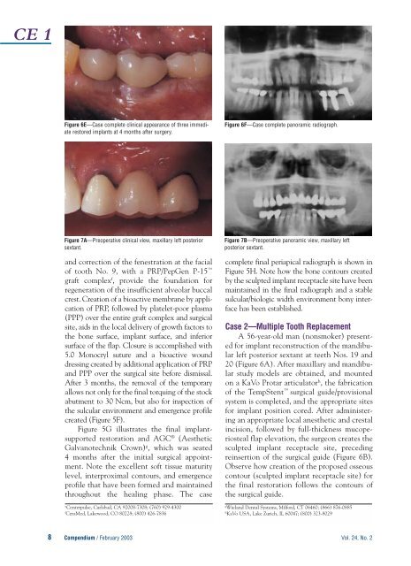
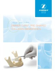
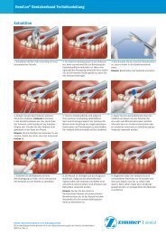
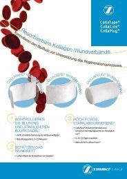
CE 1Figure 6E—Case complete clinical appearance of three immediaterestored implants at 4 months after surgery.Figure 6F—Case complete panoramic radiograph.Figure 7A—Preoperative clinical view, maxillary left posteriorsextant.<strong>and</strong> correction of the fenestration at the facialof tooth No. 9, with a PRP/PepGen P-15 graft complex f , provide the foundation forregeneration of the insufficient alveolar buccalcrest. Creation of a bioactive membrane by applicationof PRP, followed by platelet-poor plasma(PPP) over the entire graft complex <strong>and</strong> surgicalsite, aids in the local delivery of growth factors tothe bone surface, implant surface, <strong>and</strong> inferiorsurface of the flap. Closure is accomplished with5.0 Monocryl suture <strong>and</strong> a bioactive wounddressing created by additional application of PRP<strong>and</strong> PPP over the surgical site before dismissal.After 3 months, the removal of the temporaryallows not only for the final torquing of the stockabutment to 30 Ncm, but also for inspection ofthe sulcular environment <strong>and</strong> emergence profilecreated (Figure 5F).Figure 5G illustrates the final implantsupportedrestoration <strong>and</strong> AGC ® (AestheticGalvanotechnik Crown) g , which was seated4 months after the initial surgical appointment.Note the excellent soft tissue maturitylevel, interproximal contours, <strong>and</strong> emergenceprofile that have been formed <strong>and</strong> maintainedthroughout the healing phase. The caseeCenterpulse, Carlsbad, CA 92008-7308; (760) 929-4300fCeraMed, Lakewood, CO 80228; (800) 426-7836Figure 7B—Preoperative panoramic view, maxillary leftposterior sextant.complete final periapical radiograph is shown inFigure 5H. Note how the bone contours createdby the sculpted implant receptacle site have beenmaintained in the final radiograph <strong>and</strong> a stablesulcular/biologic width environment bony interfacehas been established.Case 2—Multiple Tooth ReplacementA 56-year-old man (nonsmoker) presentedfor implant reconstruction of the m<strong>and</strong>ibularleft posterior sextant at teeth Nos. 19 <strong>and</strong>20 (Figure 6A). After maxillary <strong>and</strong> m<strong>and</strong>ibularstudy models are obtained, <strong>and</strong> mountedon a KaVo Protar articulator h , the fabricationof the TempStent surgical guide/provisionalsystem is completed, <strong>and</strong> the appropriate sitesfor implant position cored. After administeringan appropriate local anesthetic <strong>and</strong> crestalincision, followed by full-thickness mucoperiostealflap elevation, the surgeon creates thesculpted implant receptacle site, precedingreinsertion of the surgical guide (Figure 6B).Observe how creation of the proposed osseouscontour (sculpted implant receptacle site) forthe final restoration follows the contours ofthe surgical guide.gWiel<strong>and</strong> <strong>Dental</strong> Systems, Milford, CT 06460; (866) 876-0885hKaVo USA, Lake Zurich, IL 60047; (800) 323-80298 Compendium / February 2003 Vol. 24, No. 2
CE 1Figure 7C—<strong>Implant</strong> placement in conjunction with sinuselevation surgery.After atraumatic coring procedures, <strong>and</strong>application of PRP in the osteotomy sites,placement of the implants is accomplished.Two Paragon Tapered Screw Vents e areplaced: a 5.7-mm diameter, 13-mm lengthimplant at the No. 19 position, <strong>and</strong> a 4.7-mmdiameter, 13-mm length implant at the No.20 position. The creation of the sculptedimplant receptacle site eliminates the countersinkingprocedure, <strong>and</strong> allows the implantcollar to remain above the crest of the bone,but within the environment of the interdentalbone height (Figure 6C). After preparing<strong>and</strong> polishing two HLA abutments e , a 4/5<strong>and</strong> 5/6 at the appropriate implant sites,placement of the abutments (Figure 6C) precedesretrofitting <strong>and</strong> marginal adaptation ofthe provisional restorations. Closure isaccomplished with 4.0 Vicryl Rapide suturein a continuous sling/horizontal mattresssuturing technique (Figure 6D). Evaluationof the patient’s occlusion confirms noocclusal contact in centric relation or lateralexcursive movements.After observation for 2 months, a fractureis detected at tooth No. 18, <strong>and</strong> a thirdimmediate restored implant is placed in them<strong>and</strong>ibular left posterior sextant. Figure 6Eshows the case complete clinical appearanceof the three immediate restored implants at4 months after surgery. Figure 6F shows thecase complete panoramic radiograph of them<strong>and</strong>ibular left posterior sextant.Case 3—Multiple Tooth Replacementwith Sinus ElevationA 63-year-old woman (nonsmoker) presentedfor treatment of a vertical fracture attooth No. 13 (Figure 7A). The preoperativepanoramic radiograph is shown in Figure 7B.Figure 7D—Abutments seated <strong>and</strong> conversion of theTempStent into the provisional restoration.After the pretreatment diagnostic <strong>and</strong> planningphase previously mentioned is completed,TempStent is fabricated not only to providesurgical guidance, but also to serve as the provisionalrestoration. Because of the pneumatizedmaxillary left sinus, sinus elevationsurgery is added to the treatment plan, in additionto placement of the three implants.After administering an appropriate localanesthetic, a sulcular incision is made at thebuccal <strong>and</strong> palatal of teeth Nos. 13 <strong>and</strong> 15,crestally at No. 14, with two vertical releasingincisions at the distal of No. 12 <strong>and</strong> distal lineangle of No. 15. After full-thickness mucoperiostealflap elevation, the creation of anosteotomy in the lateral wall of the maxillae,just inferior to the zygomatic arch, allows foraccess to, <strong>and</strong> elevation of, the lateral wall ofthe maxillae. Attached to the Schneiderianmembrane, the lateral wall <strong>and</strong> the inferiorportion of the sinus membrane itself are rotatedmedially <strong>and</strong> superiorly to create the receptaclefor the sinus graft. Insertion of the surgicalguide allows for preparation of the implantsites at the Nos. 13, 14, <strong>and</strong> 15 areas.Before implant placement, PRP isapplied to the sinus cavity via the accessopening, <strong>and</strong> the graft complex (PRP <strong>and</strong>PepGen P-15 ) is placed anteriorly, medially,<strong>and</strong> distally in the sinus. This techniqueensures that grafting material is present atthe aforementioned areas of the sinus beforeplacement of the implants. Additional applicationof PRP in the sinus precedes implantplacement. Three Paragon Tapered ScrewVent implants are placed: a 5.7-mm diameter,13-mm length at the No. 15 site, followed bytwo 4.7-mm diameter 13-mm in lengthimplants at the Nos. 13 <strong>and</strong> 14 sites, respectively(Figure 7C). After removal of theVol. 24, No. 2 Compendium / February 20039