On-The-Vehicle - aesco
On-The-Vehicle - aesco On-The-Vehicle - aesco
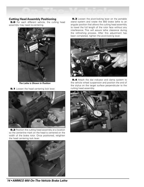
On-The-VehicleCutting Head Assembly Positioning9.0 For each different vehicle, the cutting headassembly may need re-centering.9.3 Loosen the pivot-locking lever on the portablestand system and rotate the 800 brake lathe to anangular position that allows the cutting head assemblyto travel the full length of the rotor face without anyinterference. This will assure lathe clearance duringthe refinishing process. After this adjustment hasbeen completed, tighten the pivot-locking lever.The Lathe is Shown in Position9.1 Loosen the head centering lock lever.9.4 Attach the dial indicator and clamp system tothe vehicle wheel suspension and position the end ofthe stylus on the target surface perpendicular to thecutting head assembly.9.2 Position the cutting head assembly at a locationso the centerline mark on the head is centered on thewidth of the brake rotor. Once positioned, retightenthe head centering lock lever.14 • AMMCO 800 On-The-Vehicle Brake Lathe
On-The-VehicleAdjusting the Lathe Runout10.0 At this point, the 800 brake lathe is ready tobe turned on and adjusted for runout. Start thisprocess by inserting the power cord into the twist-lockreceptacle located on the end of the control box.10.2 Turn the power switch ON.10.3 Correct for lathe runout by using the twoadjustment knobs (red and blue) located on the runoutadjustment head. First turn the red knob, then theblue knob decreasing dial indicator movement asmuch as possible until the indicator movementimproves. Continue to turn red and blue knobs alternatelyto decrease dial indicator movement. Whenmovement of dial indicator has been reduced to.004-inch or less, adjustment is complete. Notethat resulting cut will be within .002-inch.10.1 Make sure lock pin (yellow) is locked into therunout adjustment head before activating the powerswitch.Runout DiagramIndicator Distance1/2 Indicator DistanceOrigin ofMovementNote that the Dial IndicatorReads .001 (1/1000) of anInch Between the Marks.002-inchmovement atcarbide inserts.004-inchmovementat indicatorLATHEAMMCO 800 On-The-Vehicle Brake Lathe • 15
- Page 1 and 2: Safety Instructions Pgs. iii-viInst
- Page 3 and 4: Owner’s ResponsibilityTo maintain
- Page 5 and 6: Safety Notices and DecalsFor your s
- Page 7 and 8: On-The-VehicleBefore You BeginThe A
- Page 9 and 10: On-The-VehicleStandard AccessoriesP
- Page 11 and 12: On-The-Vehicle800 On-The-Vehicle Br
- Page 13 and 14: On-The-Vehicle3.6 Remove the valve
- Page 15 and 16: On-The-Vehicle5.4 Now practice usin
- Page 17 and 18: On-The-VehicleOperating Instruction
- Page 19: On-The-VehicleLathe to Vehicle Atta
- Page 23 and 24: On-The-VehicleThe mirror maybe used
- Page 25 and 26: On-The-Vehicle13.5 Inspect the roto
- Page 27 and 28: On-The-VehicleAdjustment KnobReposi
<strong>On</strong>-<strong>The</strong>-<strong>Vehicle</strong>Cutting Head Assembly Positioning9.0 For each different vehicle, the cutting headassembly may need re-centering.9.3 Loosen the pivot-locking lever on the portablestand system and rotate the 800 brake lathe to anangular position that allows the cutting head assemblyto travel the full length of the rotor face without anyinterference. This will assure lathe clearance duringthe refinishing process. After this adjustment hasbeen completed, tighten the pivot-locking lever.<strong>The</strong> Lathe is Shown in Position9.1 Loosen the head centering lock lever.9.4 Attach the dial indicator and clamp system tothe vehicle wheel suspension and position the end ofthe stylus on the target surface perpendicular to thecutting head assembly.9.2 Position the cutting head assembly at a locationso the centerline mark on the head is centered on thewidth of the brake rotor. <strong>On</strong>ce positioned, retightenthe head centering lock lever.14 • AMMCO 800 <strong>On</strong>-<strong>The</strong>-<strong>Vehicle</strong> Brake Lathe


