Squirrel-cage motors Dimensions - Siemens
Squirrel-cage motors Dimensions - Siemens
Squirrel-cage motors Dimensions - Siemens

Create successful ePaper yourself
Turn your PDF publications into a flip-book with our unique Google optimized e-Paper software.
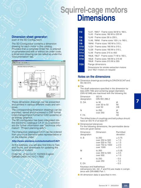
<strong>Squirrel</strong>-<strong>cage</strong> <strong>motors</strong><strong>Dimensions</strong>Dimension sheet generator:(part of the SD Configurator)The SD Configurator contains a dimensiondrawing for each motor in this catalog.Provided that a complete Order No. is enteredor parameterized with or without an order code,a dimension drawing can be called up under the"Documentation" tab.7/27/47/67/87/107/127/147/167/187/201LA7, 1MA7 · Frame sizes 56 M to 160 L1LA5 · Frame sizes 180 M to 225 M1LA9 · Frame sizes 56 to 200 L1LA6, 1MA6 · Frame sizes 100 L to 160 L1MA6 · Frame sizes 180 M to 315 L1LG4 · Frame sizes 180 M to 315 L1LG6 · Frame sizes 180 M to 315 L1LA8 · Frame sizes 315 to 4501MJ6, 1MJ7 · Frame sizes 71 M to 160 L1MJ6 · Frame sizes 180 M to 315 M1MJ8 · Frame sizes 315 M to 355Flange dimensions<strong>Dimensions</strong> for smoke extraction <strong>motors</strong>and 1MJ1 <strong>motors</strong> on requestThese dimension drawings can be presentedand printed in various different views and windows.The corresponding dimension drawings can beexported, saved and processed in DXF format(interchange/import format for CAD systems) oras bitmap graphics.The SD configurator has been integrated intothe electronic catalogue CA 01 as a selectionaid (for further information see "Technical Information","Project planning aids").The interactive catalogue CA 01 can be orderedfrom your local <strong>Siemens</strong> sales representative oron the Internet underhttp://www.siemens.com/automation/CA01At this address, you will also find links to Tipsand Tricks, and downloads for updating thefunctions or content.Order No. of the CA 01 10/2003 EnglishE86060-D4001-A110-C1-7600Notes on the dimensions■ Dimension drawings according to DIN EN 50 347 andIEC 60 072.■ FitsThe shaft extensions specified in the dimension tables(DIN 748) and centering spigot diameters(DIN 42 948) are machined with the following fits:Dimension ISO fitdesignation DIN ISO 286-2D, DA to 30 j6over 30 to 50 k6over 50m6N to 250 j6over 250h6F, FA h9The drilled holes of couplings and belt pulleys shouldhave an ISO fit of at least H7.■ Dimensional tolerancesFor the following dimensions, the permissible deviationsare given below:Dimension Dimension PermitteddesignationdeviationA, B to 250 ± 0.75over 250 to 500 ± 1.0over 500 to 750 ± 1.5over 750 to 1000 ± 2.0over 1000 ± 2.5M to 200 ± 0.25over 200 to 500 ± 0.5over 500 ± 1.0H to 250 – 0.5over 250 – 1.0E, EA – 0.5Keyways and featherkeys(dimensions GA, GC, F and FA) are made in compliancewith DIN 6885 Part 1.■ All dimension data is specified in mm.7<strong>Siemens</strong> M 11 · 2003/20047/1
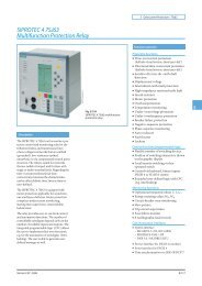
,0,<strong>Squirrel</strong>-<strong>cage</strong> <strong>motors</strong><strong>Dimensions</strong>1LA7, 1MA7 · Frame sizes 56 M to 160 L1LA5 · Frame sizes 180 M to 225 M<strong>Squirrel</strong>-<strong>cage</strong> <strong>motors</strong>■ IM B 3 +- , - - # ' % ? ) /) 5- O A > JI BH I E A / ), ** - * -* +- * - + / +, )) +, + )) 3) ) , H= A I E A I ' 5 = @ # 5 D = L AD K I E C BA A JA = ? DM EJD @ HEA @ D A I= J , -- +* )* + )* *- )0 )) ) )) *) ) , * )** * ** ) + )+ ) ■ IM B 5 and IM V1 · For flange dimensions, see Page 7/20 (Z = Number of fixing holes) + # & ' @) /) 5* -* - , )) +) 30 0 - O A > JI BH I E A - * )) ) ,/ )-- +/ +7For motorSize Type1LA7 . . .1MA7 . . .No. ofpolesDimension drawing according to IECA AA AB AC 1 ) AD AD’ AF AF’ AG AQ AS B B’ BA BA’ BB BC BE BE’ C CA CA’56 M 1LA7 050 V 2 to 4 90 25 110 116 101 101 78 78 74 – 37 71 – 28 – 87 34 32 18 36 53 –1LA7 053 V63 M . . . . 060. . . . 06371 M . . . . 070. . . . 07380 M . . . . 080. . . . 08390 S90 L, *. . . . 090. . . . 096100 L . . . . 106. . . . 107- ,2 to 6 100 27 120 124 101(135)2 to 8 112 27 132 145 111(145)2 to 8 125 30.5 150 163 120(154)2 to 8 140 30.5 165 180 128(162)2 to 84 and 8- -- )101 78(95)111 88(105)120(154), +97(114)78 74(120)124 37(60)88 74 124 37(120) (60)97(114)128 105 105(162) (122) (122)75 124 37.5(120) (60)75 170 37.5(120) (60)80 – 28 – 96 30(52.5)32 18(16)90 – 27 – 106 18 32 18(41.5) (16)100 – 32 – 118 14(36)100*100125 33 54 143 23125*(46)32 18(16)32 18(16)40 66 –45 83 –50 94 –134 4 )56 143 118160 42 196 203 135 163 78 123 120 170 60 140 – 47 – 176 39 42 21 63 125 –112 M . . . . 113 2 to 8 190 46 226 227 148 176 91 136 120 170 60 140 – 47 – 176 32 42 21 70 141 –132 S . . . . 130 2 to 8 216 53 256 267 167 194 107 154 140 250 70 140 – 49 – 180 39 42 21 89 162.5 –. . . . 131 2132 M . . . . 133 4 to 8 216 53 256 267 167 194 107 154 140 250 70 178 – 49 – 218 39 42 21 89 124.5 –. . . . 134 6162.5 5 )160 M . . . . 163 2 to 8 254 60 300 320 197 226 127 183 165 250 82.5 210 – 57 – 256 52.5 54 27 108 183 –. . . . 164 2 and 8160 L . . . . 166 2 to 8 254 60 300 320 197 226 127 183 165 250 82.5 254 – 57 – 300 52.5 54 27 108 139 –179 6 )180 M 1LA5 183 2 and 4 279 69.5 339 363 258 258 216 216 152 340 71 241 – 50 – 287 38 54 27 121 259 –180 L 1LA5 186 4 to 8 279 69.5 339 363 258 258 216 216 152 340 71 279 – 50 – 325 38 54 27 121 221 –200 L 1LA5 206 2 and 6 318 83 388 402 305 305 252 252 260 340 96 305 – 58.5 – 355 45 85 42.5 133 239 –1LA5 207 2 to 8 –225 S 1LA5 220 4 and 8 356 103 426 402 305 305 252 252 260 340 96 286* 311 58 83 361 36 85 42.5 149 248.5225 M 1LA5 223 24 to 8356 103 426 402 305 305 252 252 260 340 96 286 311* 58 83 361 36 85 42.5 149 223.5■ The dimensions in bracketsapply to 1MA7.■ For 1LA in pole-changingversion (6 or 9 terminals), thedimensions of the basic versionapply.* This dimension is assigned inDIN EN 50347 to the frame sizelisted.V The <strong>motors</strong> of frame size 56 M arenon-ventilated.1) Measured across the screwheads.2) With a cast-on terminal housing,4 knockout openings are providedfor metric threads.7/2<strong>Siemens</strong> M 11 · 2003/2004
<strong>Squirrel</strong>-<strong>cage</strong> <strong>motors</strong><strong>Dimensions</strong>1LA7, 1MA7 · Frame sizes 56 M to 160 L1LA5 · Frame sizes 180 M to 225 M■ IM B 35 · For flange dimensions, see Page 7/20 (Z = Number of fixing holes) + ) /) 5) ,0 # % A, - O A > JI BH I E A / )- *-+* -* - * +- )- +, )) +/ + )) 3) H= A I E A I ' 5 = @ # 5 D = L AD K I E C BA A JA = ? DM EJD @ HEA @ D A I= J , -, * )- , * + ) - -* )* *, +0 )) ) )) *) ) , * )** * ** ) + )+ ) ■ IM B 14 · For flange dimensions, see Page 7/20 (Z = Number of fixing holes) +0 0 # ' & ? ) /) 5* -* - - ), )) +) 3- O A > JI BH I E A - * )) ) ,/ )-- +/ +, +, *- ,- -Drive-end shaft extensionNon-drive-end shaft extensionH HA HH K K’ L LC LL LM O D DB E EB ED F GA DA DC EA EC EE FA GC756 6 69.5 5.8 9 169 200 74 – 1x M16 x 1.51x M25 x 1.563 7 69.5(92.5)71 7 63.5(86.5)80 8 63.5(86)90 10 79(101.5)7 10 202.5 232 74(120)7 10 240 278 74(120)9.5 13.5 273.5308.5 4 )32436475(120)10 14 331 389 75(120)231.5 1x M16 x 1.51x M25 x 1.5268 1x M16 x 1.51x M25 x 1.5299.5334.5 4 )1x M16 x 1.51x M25 x 1.5382.5 1x M16 x 1.51x M25 x 1.59 M3 20 14 3 3 10.2 9 M3 20 14 3 3 10.211 M4 23 16 3.5 4 12.5 11 M4 23 16 3.5 4 12.514 M5 30 22 4 5 16 14 M5 30 22 4 5 1619 M6 40 32 4 6 21.5 19 M6 40 32 4 6 21.524 M8 50 40 5 8 27 19 M6 40 32 4 6 21.5100 12 102 12 16 372 438 120 423.5 2x M32 x 1.5 2 ) 28 M10 60 50 5 8 31 24 M8 50 40 5 8 27112 12 102 12 16 393 461 120 444.5 2x M32 x 1.5 2 ) 28 M10 60 50 5 8 31 24 M8 50 40 5 8 27132 15 128 12 16 452.5 3 ) 551.5 140 505 3 ) 2x M32 x 1.5 2 ) 38 M12 80 70 5 10 41 38 M12 80 70 5 10 41132 15 128 12 16 452.5 3 )490.5 5 )551.5589.5 5 )140 505 3 )543 5 )2x M32 x 1.5 2 ) 38 M12 80 70 5 10 41 38 M12 80 70 5 10 41160 18 160.5 15 19 588 721 165 640.5 2x M32 x 1.5 2 ) 42 M16 110 90 10 12 45 42 M16 110 90 10 12 45160 18 160.5 15 19 588628 6 )721761 6 )165 640.5680.5 6 )2x M32 x 1.5 2 ) 42 M16 110 90 10 12 45 42 M16 110 90 10 12 45180 18 159 15 19 712 841 132 793.5 2 x M40 x 1.5 48 M16 110 100 5 14 51.5 48 M16 110 100 5 14 51.5180 18 159 15 19 712 841 132 793.5 2 x M40 x 1.5 48 M16 110 100 5 14 51.5 48 M16 110 100 5 14 51.5200 24 178 19 25 768.5 897 192 850 2 x M50 x 1.5 55 M20 110 100 5 16 59 55 M20 110 100 5 16 59225 24 184.5 19 25 806 933.5 192 887.5 2 x M50 x 1.5 60 M20 140 125 7.5 18 64 55 M20 110 100 5 16 59225 24 184.5 19 25 776 903.5 192 857.5 2 x M50 x 1.5 55 M20 110 100 5 16 59 55 M20 110 100 5 16 59806 933.5 887.560 M20 140 125 7.5 18 643) In a low-noise version, the dimensionL is 8 mm greater and the dimensionLM is 11.5 mm greater.4) For 1MA7 083-6.5) For 1MA7 133-4.6) For 1MA7 166-4 and 1MA7 166-6.<strong>Siemens</strong> M 11 · 2003/20047/3
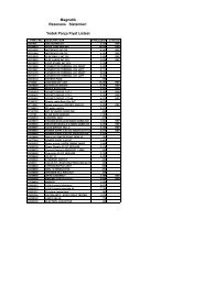
,<strong>Squirrel</strong>-<strong>cage</strong> <strong>motors</strong><strong>Dimensions</strong>1LA9 · Frame sizes 56 M to 200 L■ IM B 3 +- , - - # ' % ? ) /) 5, ** - * -* +- * - + / +, )) + )) 3) ) ,0 ),0- O A > JI BH I E A / ), + H= A I E A I ' 5 = @ # 5 D = L AD K I E C BA A JA = ? DM EJD @ HEA @ D A I= J , -- +* )* + )* *- )) ) )) *) ) , * )** * ** ) + )+ ) ■ IM B 5 and IM V1 · For flange dimensions, see Page 7/20 (Z = Number of fixing holes) + # ! & =) /) 5* -* - , )) +) 30 0 - - - O A > JI BH I E A - * )) ) ,/ )-- +/ +7For motorSize Type1LA9 . . .56 M . . . . 050 V. . . . 053 V63 M . . . . 060. . . . 06371 M . . . . 070. . . . 07380 M . . . . 080. . . . 08390 S90 L, *No. ofpoles. . . . 090 2 to 6. . . . 096-6K 2 to 6. . . . 096100 L . . . . 106. . . . 107- ,Dimension drawing according to IECA AA AB AC 1 ) AD AD’ AF AF’ AG AQ AS B B’ BA BA’ BB BC BE BE’ C CA CA’2 and 4 90 25 110 116 101 101 78 78 74372 and 4 100 27 120 124 101 101 78 78 74372 and 4 112 30.5 132 145 111 111 88 88 7437– 37 71 – 28 – 87 34 32 18 36 53 –124 37 80 – 28 – 96 30 32 18 40 66 –92124 37 90 – 27 – 106 18 32 18 45 83 –2 and 4 125 30.5 150 163 120 120 97 97 75 124 37.5 100 – 32 – 118 14 32 18 50 941342 to 64- )140 30.5 165 180 128 128 105 105 75 170 37.5 100*100, +125 33 54 143 23 32 18 56 143 118125*160 42 196 203 135 163 78 123 120 170 60 140 – 47 – 176 39 42 21 63 160195 5 )112 M . . . . 113 2 to 6 190 46 226 227 148 176 91 136 120 170 60 140 – 47 – 176 32 42 21 70 179 –132 S . . . . 130 2 and 4 216 53 256 267 167 194 107 154 140 250 70 140 – 49 – 180 39 42 21 89 162.5 –. . . . 131 2200.5132 M . . . . 133 6 216 53 256 267 167 194 107 154 140 250 70 178 – 49 – 218 39 42 21 89 124.5 –. . . . 133. . . . 13446162.5160 M . . . . 163 2 to 6 254 60 300 320 197 226 127 183 165 250 82.5 210 – 57 – 256 52.5 54 27 108 183 –. . . . 164 2160 L . . . . 166 2 to 6 254 60 300 320 197 226 127 183 165 250 82.5 254 – 57 – 300 52.5 54 27 108 179 –180 M . . . . 183 2 and 4 279 69.5 339 363 258 258 216 216 152 340 71 241 – 50 – 287 38 54 27 121 259 –180 L . . . . 186 4 and 6 279 69.5 339 363 258 258 216 216 152 340 71 279 – 50 – 325 38 54 27 121 221 –200 L . . . . 206 2 and 6 318 83 388 402 305 305 252 252 260 340 96 305 – 58.5 – 355 45 85 42.5 133 239 –. . . . 207 2 to 6––* This dimension is assigned inDIN EN 50347 to the frame sizelisted.V The <strong>motors</strong> of frame size 56 M arenon-ventilated.1) Measured across the screwheads.2) With a cast-on terminal housing,4 knockout openings are providedfor metric threads.3) For 1LA9 096-6KA.4) For 1LA9 096-2 and 1LA9 096-4.5) For 1LA9 107-4KA.7/4<strong>Siemens</strong> M 11 · 2003/2004
<strong>Squirrel</strong>-<strong>cage</strong> <strong>motors</strong><strong>Dimensions</strong>1LA9 · Frame sizes 56 M to 200 L■ IM B 35 · For flange dimensions, see Page 7/20 (Z = Number of fixing holes) + # ! ' =) /) 5) ,0, - O A > JI BH I E A / )- *-+* -* - * +- )- +, )) +/ + )) 3) H= A I E A I ' 5 = @ # 5 D = L AD K I E C BA A JA = ? DM EJD @ HEA @ D A I= J , -, * )- , * + ) - -* )* *, +0 )) ) )) *) ) , * )** * ** ) + )+ ) ■ IM B 14 · For flange dimensions, see Page 7/20 (Z = Number of fixing holes) +0 0 # ' & ? ) /) 5* -* - - ), )) +) 3- O A > JI BH I E A - * )) ) ,/ )-- +/ +, +, *- ,- -Drive-end shaft extensionNon-drive-end shaft extensionH HA HH K K’ L LC LL LM O D DB E EB ED F GA DA DC EA EC EE FA GC756 6 69.5 5.8 9 169 200 74 – 1x M16 x 1.51x M25 x 1.563 7 69.5 7 10 202.5228.523225874 231.5257.51x M16 x 1.51x M25 x 1.571 7 63.5 7 10 240 278 74 268 1x M16 x 1.51x M25 x 1.580 8 63.5 9.5 13.5 273.5308.590 10 79 10 14 331376 3 )358 4 )100 12 102 12 16 407442 5 )324364389434 3 )414 4 )473508 5 )75 299.5334.575 382.5427.5 3 )409.5 4 )120 458.5493 5 )1x M16 x 1.51x M25 x 1.51x M16 x 1.51x M25 x 1.59 M3 20 14 3 3 10.2 9 M3 20 14 3 3 10.211 M4 23 16 3.5 4 12.5 11 M4 23 16 3.5 4 12.514 M5 30 22 4 5 16 14 M5 30 22 4 5 1619 M6 40 32 4 6 21.5 19 M6 40 32 4 6 21.524 M8 50 40 5 8 27 19 M6 40 32 4 6 21.52x M32 x 1.5 2 ) 28 M10 60 50 5 8 31 24 M8 50 40 5 8 27112 12 102 12 16 431 499 120 482.5 2x M32 x 1.5 2 ) 28 M10 60 50 5 8 31 24 M8 50 40 5 8 27132 15 128 12 16 452.5 551.5 140 505 2x M32 x 1.5 2 ) 38 M12 80 70 5 10 41 38 M12 80 70 5 10 41490.5 589.5 543132 15 128 12 16 452.5490.5551.5589.5140 5055432x M32 x 1.5 2 ) 38 M12 80 70 5 10 41 38 M12 80 70 5 10 41160 18 160.5 15 19 588 721 165 640.5 2x M40 x 1.5 2 ) 42 M16 110 90 10 12 45 42 M16 110 90 10 12 45160 18 160.5 15 19 628 761 165 680.5 2x M40 x 1.5 2 ) 42 M16 110 90 10 12 45 42 M16 110 90 10 12 45180 18 159 15 19 712 841 132 793.5 2 x M40 x 1.5 48 M16 110 100 5 14 51.5 48 M16 110 100 5 14 51.5180 18 159 15 19 712 841 132 793.5 2 x M40 x 1.5 48 M16 110 100 5 14 51.5 48 M16 110 100 5 14 51.5200 24 178 19 25 768.5 897 192 850 2 x M50 x 1.5 55 M20 110 100 5 16 59 55 M20 110 100 5 16 59<strong>Siemens</strong> M 11 · 2003/20047/5
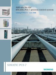
,<strong>Squirrel</strong>-<strong>cage</strong> <strong>motors</strong><strong>Dimensions</strong>1LA6, 1MA6 · Frame sizes 100 L to 160 L■ IM B 3 +- , - - # & =) /) 5 , )* - * -* +- * - + / +) +,0/ ) )) 3) ) ,, *, +- +* )* + )* *- )0 )) ) )) *) ) , ■ IM B 5 and IM V1 · For flange dimensions, see Page 7/20 (Z = Number of fixing holes) + # ' =) /) 5* -* - ) +) 30 0 - - - *, ) )) ) ,/ )-- +/ +7, *- ,- ), +For motorDimension drawing according to IECSize Type No. of A AA AB AC 1 ) AD AD’ AF AF’ AG AQ AS B BA BB BC BE BE’ C CA H HA1LA6 . . .1MA6 . . .poles100 L . . . . 106 2 to 8 160 40 196 201 164 164 124 124 121 170 60.5 140 46 180 42 42 21 63 125 100 12. . . . 107 4 and 8112 M . . . . 113 2 to 8 190 42.5 226 225.5 178 178 138 138 121 170 60.5 140 46 180 34 42 21 70 141 112 15132 S . . . . 130 2 to 8 216 50 256 265 194 194 154 154 141 250 70.5 140 47 180 42 42 21 89 162.5 132 17. . . . 131 2132 M . . . . 133 4 to 8 216 50 256 265 194 194 154 154 141 250 70.5 178 49 218 42 42 21 89 124.5 132 17. . . . 134 6160 M . . . . 163 2 to 8 254 60 300 320 226 226 183 183 166 250 83 210 63 256 52 54 27 108 183 160 18. . . . 164 2 and 8160 L . . . . 166 2 to 8 254 60 300 320 226 226 183 183 166 250 83 254 63 300 52 54 27 108 139 160 18) ) , 1) Measured across the screwheads.7/6<strong>Siemens</strong> M 11 · 2003/2004
<strong>Squirrel</strong>-<strong>cage</strong> <strong>motors</strong><strong>Dimensions</strong>1LA6, 1MA6 · Frame sizes 100 L to 160 L■ IM B 35 · For flange dimensions, see Page 7/20 (Z = Number of fixing holes) + # ! =) /) 5) ,,* -- ), )) +0 - ** - )) 3) / )-+* +- +/ +, * )- , * + ) - -* )* *, +0 )) ) )) *) ) , ■ IM B 14 · For flange dimensions, see Page 7/20 (Z = Number of fixing holes) +0 0 # ! = ) /) 5* -* - - ), )) +) 3- * )) ) ,/ )-- +/ +, +, *- ,- -Drive-end shaft extensionNon-drive-end shaft extensionHH K K’ L LC LL LM O D DB E EB ED F GA DA DC EA EC EE FA GC7104.5 12 16 372 438 121 423.5 2x M32 x 1.5 28 M10 60 50 5 8 31 24 M8 50 40 5 8 27104.5 12 16 393 461 121 444.5 2x M32 x 1.5 28 M10 60 50 5 8 31 24 M8 50 40 5 8 27130.5 12 16 453.5 551.5 141 506 2x M32 x 1.5 38 M12 80 70 5 10 41 38 M12 80 70 5 10 41130.5 12 16 453.5 551.5 141 506 2x M32 x 1.5 38 M12 80 70 5 10 41 38 M12 80 70 5 10 41160 14.5 18 588 721 166 640.5 2 x M40 x 1.5 42 M16 110 90 10 12 45 42 M16 110 90 10 12 45160 14.5 18 588 721 166 640.5 2 x M40 x 1.5 42 M16 110 90 10 12 45 42 M 16 110 90 10 12 45<strong>Siemens</strong> M 11 · 2003/20047/7
,<strong>Squirrel</strong>-<strong>cage</strong> <strong>motors</strong><strong>Dimensions</strong>1MA6 · Frame sizes 180 M to 315 L■ IM B 3 + # ! ' >) 5* -) +) 30- ,- -, ) /- *- +, ) )) ) ,/ )* +/ +0 ), *-+* )** * ** ) ■ IM B 5 and IM V1 · For flange dimensions, see Page 7/20 (Z = Number of fixing holes)- , + + )+ ) - )- -, + # " ?Frame sizes 180 M/L, 225 S/M,280 S/M and 315 S/M havehousing feet each with 2 drilled holesat NDE.Type of construction IM B 5 / IM V 1(only up to frame size 315 M) ) ) )) *) 5) ) )) , ) /- ** -- +, ) )) ) +) 3) ,/ )-/ +) 07For motorSize Type1MA6 . . .No. ofpolesDimension drawing according to IECA AA AB AC 1 ) AD AD’ AF AF’ AG AH AQ AS B B’ BA BA’ BB BC BE C CA CA’180 M . . . . 183 2 279 65 344 375 274 274 227 227 220 470 340 82 241* 279 70 108 319 35 75 121 259 –4180 L . . . . 186 4 to 8 279 65 344 375 274 274 227 227 220 470 340 82 241 279* 70 108 319 35 75 121 – 221200 L . . . . 206 2 318 80 398 402 308 308 248 248 262 530 340 99 305 – 85 85 355 42 85 133 239 –6. . . . 207 24 to 8318 80 398 402 308 308 248 248 262 530 340 99 305 – 85 85 355 42 85 133 239 –225 S225 M, *. . . . 220. . . . 2234 and 824 to 8250 M . . . . 253 24 to 8280 S . . . . 280 24 to 8280 M . . . . 283 24 to 8315 S . . . . 310 24 to 8315 M . . . . 313 2315 L . . . . 316. . . . 317. . . . 3180 04 to 824 to 86 and 8356356- ) , +The <strong>motors</strong> are supplied with two fitted eyebolts conforming to IM B 5, wherebyone can be repositioned to conform to IM V 1 or IM V 3. Care must be taken to avoidforces perpendicular to the ring.8080436436442442339339339339269269269269264264580580425425406 100 506 505 427 427 333 333 338 645 470 120 349 – 100 100 409 39 95 168 283 –457 100 557 555 452 452 358 358 338 700 525 120 368* 419 100 151 471 30 95 190 317 –457 100 557 555 452 452 358 358 338 700 525 120 368 419* 100 151 471 30 95 190 – 266508 120 628 620 515 515 395 395 405 805 590 134 406* 457 125 171 527 32 90 216 358 –508 120 628 620 515 515 395 395 405 805 590 134 406 457* 125 171 527 32 90 216 – 307508 120 628 620 515 515 395 395 405 805 590 134 508 – 120 120 578 32 90 216 396 –100100286*286311311*858511011036136125258585149149269––244■ <strong>Dimensions</strong> for 9-terminalbox on request.* This dimension is assigned inDIN EN 50347 to the frame sizelisted.1) Measured across the screwheads.2) For version with low-noise fan.3) In the low-noise version, a secondshaft end and/or top-mountedsensor is not possible.7/8<strong>Siemens</strong> M 11 · 2003/2004
,<strong>Squirrel</strong>-<strong>cage</strong> <strong>motors</strong><strong>Dimensions</strong>1MA6 · Frame sizes 180 M to 315 L■ IM B 35 · For flange dimensions, see Page 7/20 (Z = Number of fixing holes) + # " ? ) 5) /* -- * - +) +) 30- ,, ) )) ) ,/ )-+ * +/ +0 ), ** )** * ** ) + )+ ) - -- ), +) ) )) *) ) )) , Drive-end shaft extensionNon-drive-end shaft extensionH HA HH K K’ L L ’2 ) LC 3 ) LL LM LM ’2 ) O D DB E EB ED F GA DA DC EA EC EE FA GC7180 26 156 15 20 715 770–841 164 796.5 885–2 x M40 x 1.5 48 M 16 110 100 5 14 51.5 48 M 16 110 100 5 14 51.5180 26 156 15 20 715 – 841 164 796.5 – 2 x M40 x 1.5 48 M 16 110 100 5 14 51.5 48 M 16 110 100 5 14 51.5200 34 175 19 25 819.5 897 197 853 901 2 x M50 x 1.5 55 M 20 110 100 5 16 59 48 M 16 110 100 5 14 51.5771.5 ––55 M 2016 59200 34 175 19 25 771.5 819.5–897 197 853 901–2 x M50 x 1.5 55 M 20 110 100 5 16 59 4855M 16M 20110 100 5 141651.5592252253434174 19174 192525839809839–855–250 42 207 24 30 935 1010–280 42 220 24 30 1010 1080–280 42 220 24 30 1010 1080–315 52 248 28 35 1114 11851144 –315 52 248 28 35 1114 11851144315 52 248 28 35 125412841284–1325––954924954200200935909935–955–10501080234 1035 1110–1155 234 1120 1230–1155 234 1120 1230–2 x M50 x 1.5 602 x M50 x 1.5 55602 x M63 x 1.5 60652 x M63 x 1.5 65752 x M63 x 1.5 6575M 20 140M 20 11014012510012510510181618645964M 20 140 125 10 18 6469M 20 140 125 10 18 6920M 20 140 125 10 182012601290266 122412541295–2 x M63 x 1.5 6580M 20 14017012514010 18221260 266 1224 1295 2 x M63 x 1.5 65 M 20 140 125 10 181290 1254 –80 170 140 221400 266 1364 1435 2 x M63 x 1.5 65 M 20 140 125 10 181430 1394 –80 170 140 221430 1394 –80 170 140 2279.56979.56985698569858555485555606065606560706070607070M 20 110M 16 110M 20M 20 110140100100100100125105101614165 16185951.5595964M 20 140 125 10 18 6469M 20 140 125 10 18 6469M 20 140 125 10 18 6420 74.5M 20 140 125 10 18 6420 74.5M 20 140 125 10 18 6420 74.520 74.5<strong>Siemens</strong> M 11 · 2003/20047/9
,<strong>Squirrel</strong>-<strong>cage</strong> <strong>motors</strong><strong>Dimensions</strong>1LG4 · Frame sizes 180 M to 315 L■ IM B 3 + - - # >) 5) /* -) +) 3,0- , - *- +, ) )) ) ,/ )* +/ +0 )Frame sizes 180 M/L, 225 S/M,, *, +- +*+ ) - )280 S/M and 315 S/M/L have housing* + ) feet each with 2 drilled holes at NDE* + ) (Exception: 1LG4 318-6 <strong>motors</strong> have* )* ) housing feet each with 3 drilled holes* *at NDE).■ IM B 5 and IM V1 · For flange dimensions, see Page 7/20 (Z = Number of fixing holes)- , + - - # " ?Type of construction IM B 5 / IM V 1(only up to frame size 315 M) ) ) ) )) )) , ) *) /) 5- ** -- +, )) + )) 3) ) ,/ )-/ +) 07, *For motorSize Type1LG4 . . .No. ofpoles0 0- ) , +The <strong>motors</strong> are supplied with two fitted eyebolts conforming to IM B 5, whereby onecan be repositioned to conform to IM V 1 or IM V 3. Care must be taken to avoid forcesperpendicular to the ring.Dimension drawing according to IECA AA AB AC 1 ) AD AD’ AF AF’ AG AH AQ AS B B’ B’’ BA BA’ BB BC BE C CA CA’180 M . . . . 183 2 and 4 279 65 339 363 262 262 218 218 152 452 340 71 241* 279 – 70 111 328 36 54 121 202* 164180 L . . . . 186 4 to 8 279 65 339 363 262 262 218 218 152 452 340 71 241 279* – 70 111 328 36 54 121 202 164*. . . . 188 2 to 8 279 65 339 363 262 262 218 218 152 452 340 71 241 279* – 70 111 328 36 54 121 253 215*200 L . . . . 206 2 and 6 318 70 378 402 300 300 247 247 260 486 340 96 305 – – 80 80 355 63 85 133 177 –. . . . 207 2 to 8 318 70 378 402 300 300 247 247 260 486 340 96 305 – – 80 80 355 63 85 133 177 –. . . . 208 2 and 6 318 70 378 402 300 300 247 247 260 486 340 96 305 – – 80 80 355 63 85 133 234 –4 and 8 177225 S . . . . 220 4 and 8 356 80 436 442 325 325 272 272 260 556 425 96 286* 311 – 85 110 361 47 85 149 218* 193225 M . . . . 223 2 356 80 436 442 325 325 272 272 260 556 425 96 286 311* – 85 110 361 47 85 149 218 193*4 to 8. . . . 228 2 356 80 436 442 325 325 272 272 260 556 425 96 286 311* – 85 110 361 47 85 149 278 253*4 to 8250 M . . . . 253 2 406 100 490 495 392 392 308 308 300 620 470 117 349 – – 100 100 409 69 110 168 235 –4 to 8. . . . 258 2 406 100 490 495 392 392 308 308 300 620 470 117 349 – – 100 100 409 69 110 168 235 –4 3056 and 8 235280 S . . . . 280 2 457 100 540 555 432 432 348 348 300 672 525 118 368* 419 – 100 151 479 62 110 190 267* 2164 to 8280 M . . . . 283 2 457 100 540 555 432 432 348 348 300 672 525 118 368 419* – 100 151 479 62 110 190 267 216*4 to 8. . . . 288 2 457 100 540 555 432 432 348 348 300 672 525 118 368 419* – 100 151 479 62 110 190 377 326*46 and 8 267 216*315 S . . . . 310 2 508 120 610 610 495 495 406 406 379 780 590 154 406* 457 – 125 176 527 69 110 216 315* 264. . . . 310 4 to 8315 M . . . . 313 2 508 120 610 610 495 495 406 406 379 780 590 154 406 457* – 125 176 527 69 110 216 315 264*. . . . 313 4 to 8315 L 4 ) . . . . 316/317 2 508 120 610 610 495 495 406 406 379 780 590 154 457 508* – 125 176 578 69 110 216 424 373*. . . . 316/317 4 to 8. . . . 318 8. . . . 318 6 508 120 610 610 495 495 406 406 379 780 590 154 406 457 508* 155 250 666 69 110 216 615 564* This dimension is assigned inDIN EN 50347 to the frame sizelisted.1) Measured across the screwheads.2) In version with low-noise fan for2-pole <strong>motors</strong>.3) In the low-noise version, a secondshaft end and/or top-mountedsensor is not possible.7/10<strong>Siemens</strong> M 11 · 2003/2004
,<strong>Squirrel</strong>-<strong>cage</strong> <strong>motors</strong><strong>Dimensions</strong>1LG4 · Frame sizes 180 M to 315 L■ IM B 35 · For flange dimensions, see Page 7/20 (Z = Number of fixing holes) + #) 5) /* -- * - +) +, )) 30- ,- - )) ) ,/ )-+ * +/ +0 ), ** )*+ )* + ) * + ) * ) * *- ), +) ) )) *) ) , ) )<strong>Squirrel</strong>-<strong>cage</strong> <strong>motors</strong>Drive-end shaft extension Non-drive-end shaft extensionCA’’ H HA HH K K’ L L ’2 ) LC 3 ) LL LM LM ’2 ) O D DB E EB ED F GA DA DC EA EC EE FA GC7180 20 157 15 19 668.5 668.5 784 132 758.5 758.5 2 x M40 x 1.5 48 M 16 110 100 5 14 51.5 48 M 16 110 100 5 14 51.5180 20 157 15 19 668.5 784 132 758.5 2 x M40 x 1.5 48 M 16 110 100 5 14 51.5 48 M 16 110 100 5 14 51.5180 20 157 15 19 719.5 719.5 835 132 809.5 809.5 2 x M40 x 1.5 48 M 16 110 100 5 14 51.5 48 M 16 110 100 5 14 51.5200 25 196 19 25 720 754 835 192 810 844 2 x M50 x 1.5 55 M 20 110 100 5 16 59 55 M 20 110 100 5 16 59200 25 196 19 25 720 754 835 192 810 844 2 x M50 x 1.5 55 M 20 110 100 5 16 59 55 M 20 110 100 5 16 59200 25 196 19 25 777 811 892 192 867 901 2 x M50 x 1.5 55 M 20 110 100 5 16 59 55 M 20 110 100 5 16 59720 835 810225 34 196 19 25 789 903 192 889 2 x M50 x 1.5 60 M 20 140 125 10 18 64 55 M 20 110 100 5 16 59225 34 196 19 25 759 793 873 192 859 893 2 x M50 x 1.5 55 M 20 110 100 5 16 59 48 M 16 110 100 5 14 51.5789 903 889 60 M 20 140 125 10 18 64 55 M 20 110 100 5 16 59225 34 196 19 25 819 853 933 192 919 953 2 x M50 x 1.5 55 M 20 110 100 5 16 59 48 M 16 110 100 5 14 51.5849 963 949 60 M 20 140 125 10 18 64 55 M 20 110 100 5 16 59250 40 237 24 30 887 924 1002 236 987 1024 2 x M63 x 1.5 60 M 20 140 125 10 18 64 55 M 20 110 100 5 16 591032 65 M 20 140 125 10 18 69 60 M 20 140 125 10 18 64250 40 237 24 30 887 924 1002 236 987 1024 2 x M63 x 1.5 60 M 20 140 125 10 18 64 55 M 20 110 100 5 16 59957 1102 1057 65 M 20 140 125 10 18 69 60 M 20 140 125 10 18 64887 1032 987 65 M 20 140 125 10 18 69 60 M 20 140 125 10 18 64280 40 252 24 30 960 998 1105 236 1070 1108 2 x M63 x 1.5 65 M 20 140 125 10 18 69 60 M 20 140 125 10 18 6475 M 20 140 125 10 20 79.5 65 M 20 140 125 10 18 69280 40 252 24 30 960 998 1105 236 1070 1108 2 x M63 x 1.5 65 M 20 140 125 10 18 69 60 M 20 140 125 10 18 6475 M 20 140 125 10 20 79.5 65 M 20 140 125 10 18 69280 40 252 24 30 1070 1108 1215 236 1180 1218 2 x M63 x 1.5 65 M 20 140 125 10 18 69 60 M 20 140 125 10 18 6475 M 20 140 125 10 20 79.5 65 M 20 140 125 10 18 69960 1105 1070 75 M 20 140 125 10 20 79.5 65 M 20 140 125 10 18 69315 50 285 28 35 1072 1142 1217 307 1182 1252 2 x M63 x 1.5 65 M 20 140 125 10 18 69 60 M 20 140 125 10 18 641102 1247 1212 80 M 20 170 140 10 22 85 70 M 20 140 125 10 20 74.5315 50 285 28 35 1072 1142 1217 307 1182 1252 2 x M63 x 1.5 65 M 20 140 125 10 18 69 60 M 20 140 125 10 18 641102 1247 1212 80 M 20 170 140 10 22 85 70 M 20 140 125 10 20 74.5315 50 285 28 35 1232 1302 1377 307 1342 1412 2 x M63 x 1.5 65 M 20 140 125 10 18 69 60 M 20 140 125 10 18 641262 1407 1372 80 M 20 170 140 10 22 85 70 M 20 140 125 10 20 74.580 M 20 170 140 10 22 85 70 M 20 140 125 10 20 74.5513* 315 30 285 28 35 1402 1547 307 1512 2 x M63 x 1.5 80 M 20 170 140 10 22 85 70 M 20 140 125 10 20 74.54) For terminal box system ordercodes (K09, K10, K11), screwedfeet with foot dimensionsBB = 666 mm only (see "TechnicalInformation", "Eyebolts").<strong>Siemens</strong> M 11 · 2003/20047/11
,<strong>Squirrel</strong>-<strong>cage</strong> <strong>motors</strong><strong>Dimensions</strong>1LG6 · Frame sizes 180 M to 315 L■ IM B 3 + - - # >) 5) /* -) +) 3,0- , - *- +, ) )) ) ,/ )* +/ +0 )Frame sizes 180 M/L, 225 S/M,, *, + 280 S/M and 315 S/M/L have housing- +*+ ) - )* + ) feet each with 2 drilled holes at NDE+ ) (Exception: 2-, 4- and 6-pole 1LG6 317* * )* ) <strong>motors</strong> and 1LG6 318 <strong>motors</strong> have housingfeet each with 3 drilled holes at NDE).* *■ IM B 5 and IM V1 · For flange dimensions, see Page 7/20 (Z = Number of fixing holes)- , + - - # " ?Type of construction IM B 5 / IM V 1(only up to frame size 315 M) ) ) ) )) )) , ) *) /) 5Frame size IM V 1- ** -- +) +, )) 3 )) ) ,/ )-/ +) 07, *For motorSize Type1LG6 . . .No. ofpoles0 0- ) , +The <strong>motors</strong> are supplied with two fitted eyebolts conforming to IM B 5, whereby onecan be repositioned to conform to IM V 1 or IM V 3. Care must be taken to avoid forcesperpendicular to the ring.Dimension drawing according to IECA AA AB AC 1 ) AD AD’ AF AF’ AG AH AQ AS B B’ B’’ BA BA’ BB BC BE C CA CA’180 M . . . . 183 2 279 65 339 363 262 262 218 218 152 452 340 71 241* 279 – 70 111 328 36 54 121 253* 2154 202* 164180 L . . . . 186 4 to 8 279 65 339 363 262 262 218 218 152 452 340 71 241 279* – 70 111 328 36 54 121 253 215*200 L . . . . 206 2 and 6 318 70 378 415 300 300 247 247 260 486 340 96 305 – – 80 80 355 63 85 133 177 –. . . . 207 2 and 6 318 70 378 415 300 300 247 247 260 486 340 96 305 – – 80 80 355 63 85 133 234 –4 and 8 177225 S . . . . 220 4 and 8 356 80 436 442 325 325 272 272 260 556 425 96 286* 311 – 85 110 361 47 85 149 218* 193225 M . . . . 223 2 356 80 436 442 325 325 272 272 260 556 425 96 286 311* – 85 110 361 47 85 149 278 253*4 to 8. . . . 228 2 356 80 436 442 325 325 272 272 260 556 425 96 286 311* – 85 110 361 47 85 149 328 303*4 to 6250 M . . . . 253 2 406 100 490 495 392 392 308 308 300 620 470 118 349 – – 100 100 409 69 110 168 235 –4 3056 and 8 235. . . . 258 2 406 100 490 495 392 392 308 308 300 620 470 118 349 – – 100 100 409 69 110 168 305 –4 to 6280 S . . . . 280 2 457 100 540 555 432 432 348 348 300 672 525 118 368* 419 – 100 151 479 62 110 190 267* 2164 to 8280 M . . . . 283 2 457 100 540 555 432 432 348 348 300 672 525 118 368 419* – 100 151 479 62 110 190 377 326*46 and 8 267 216*. . . . 288 2 457 100 540 555 432 432 348 348 300 672 525 118 368 419* – 100 151 479 62 110 190 377 226*4 to 6315 S . . . . 310 2 508 120 610 610 495 495 406 406 379 780 590 154 406* 457 – 125 176 527 69 110 216 315* 264. . . . 310 4 to 8315 M . . . . 313 8 508 120 610 610 495 495 406 406 379 780 590 154 406 457* – 125 176 527 69 110 216 315 264*. . . . 313 2 508 120 610 610 495 495 406 406 379 780 590 154 457* 508 – 125 176 578 69 110 216 424* 373. . . . 313 4 and 6315 L 4 ) . . . . 316 2 508 120 610 610 495 495 406 406 379 780 590 154 457 508* – 125 176 578 69 110 216 424 373*. . . . 316 4 and 6. . . . 316/317 8. . . . 317/318 2 508 120 610 610 495 495 406 406 379 780 590 154 406 457 508* 155 250 666 69 110 216 615 564. . . . 317/318 4 and 6. . . . 318 8* This dimension is assigned inDIN EN 50347 to the frame sizelisted.1) Measured across the screwheads.2) For version with low-noise fan.3) In the low-noise version, a secondshaft end and/or top-mountedsensor is not possible.7/12<strong>Siemens</strong> M 11 · 2003/2004
,<strong>Squirrel</strong>-<strong>cage</strong> <strong>motors</strong><strong>Dimensions</strong>1LG6 · Frame sizes 180 M to 315 L■ IM B 35 · For flange dimensions, see Page 7/20 (Z = Number of fixing holes) + #) 5) /* -- * - +) +, )) 30- ,- - )) ) ,/ )-+ * +/ +0 ), ** )*+ )* + ) * + ) * ) * *- ), +) ) )) *) ) , ) )<strong>Squirrel</strong>-<strong>cage</strong> <strong>motors</strong>Drive-end shaft extensionNon-drive-end shaft extensionCA’’ H HA HH K K’ L L ’2 ) LC 3 ) LL LM LM ’2 ) O D DB E EB ED F GA DA DC EA EC EE FA GC7180 20 157 15 19 719.5 835 132 809.5 2 x M40 x 1.5 48 M 16 110 100 5 14 51.5 48 M 16 110 100 5 14 51.5668.5 784 758.5180 20 157 15 19 719.5 835 132 809.5 2 x M40 x 1.5 48 M 16 110 100 5 14 51.5 48 M 16 110 100 5 14 51.5200 25 196 19 25 756 835 192 846 2 x M50 x 1.5 55 M 20 110 100 5 16 59 55 M 20 110 100 5 16 59200 25 196 19 25 813 892 192 903 2 x M50 x 1.5 55 M 20 110 100 5 16 59 55 M 20 110 100 5 16 59756 835 846225 34 196 19 25 789 903 192 889 2 x M50 x 1.5 60 M 20 140 125 10 18 64 55 M 20 110 100 5 16 59225 34 196 19 25 819 933 192 919 2 x M50 x 1.5 55 M 20 110 100 5 16 59 48 M 16 110 100 5 14 51.5849 963 949 60 M 20 140 125 10 18 64 55 M 20 110 100 5 16 59225 34 196 19 25 869 983 192 969 2 x M50 x 1.5 55 M 20 110 100 5 16 59 48 M 16 110 100 5 14 51.5900 1013 1000 60 M 20 140 125 10 18 64 55 M 20 110 100 5 16 59250 40 237 24 30 887 1002 236 987 2 x M63 x 1.5 60 M 20 140 125 10 18 64 55 M 20 110 100 5 16 59957 1102 1057 65 M 20 140 125 10 18 69 60 M 20 140 125 10 18 64887 1032 987 65 M 20 140 125 10 18 69 60 M 20 140 125 10 18 64250 40 237 24 30 957 1102 236 1057 2 x M63 x 1.5 60 M 20 140 125 10 18 64 55 M 20 110 100 5 16 5965 M 20 140 125 10 18 69 60 M 20 140 125 10 18 64280 40 252 24 30 960 1105 236 1070 2 x M63 x 1.5 65 M 20 140 125 10 18 69 60 M 20 140 125 10 18 6475 M 20 140 125 10 20 79.5 65 M 20 140 125 10 18 69280 40 252 24 30 1070 1215 236 1180 2 x M63 x 1.5 65 M 20 140 125 10 18 69 60 M 20 140 125 10 18 6475 M 20 140 125 10 20 79.5 65 M 20 140 125 10 18 69960 1105 1070 75 M 20 140 125 10 20 79.5 65 M 20 140 125 10 18 69280 40 252 24 30 1070 1215 236 1180 2 x M63 x 1.5 65 M 20 140 125 10 18 69 60 M 20 140 125 10 18 6475 M 20 140 125 10 20 79.5 65 M 20 140 125 10 18 69315 50 285 28 35 1072 1217 307 1182 2 x M63 x 1.5 65 M 20 140 125 10 18 69 60 M 20 140 125 10 18 641102 1247 1212 80 M 20 170 140 10 22 85 70 M 20 140 125 10 20 74.5315 50 285 28 35 1102 1247 307 1212 2 x M63 x 1.5 80 M 20 170 140 10 22 85 70 M 20 140 125 10 20 74.5315 50 285 28 35 1232 1377 307 1342 2 x M63 x 1.5 65 M 20 140 125 10 18 69 60 M 20 140 125 10 18 641262 1407 1372 80 M 20 170 140 10 22 85 70 M 20 140 125 10 20 74.5315 50 285 28 35 1232 1377 307 1342 2 x M63 x 1.5 65 M 20 140 125 10 18 69 60 M 20 140 125 10 18 641262 1407 1372 80 M 20 170 140 10 22 85 70 M 20 140 125 10 20 74.580 M 20 170 140 10 22 85 70 M 20 140 125 10 20 74.5513* 315 30 285 28 35 1372 1517 307 1482 2 x M63 x 1.5 65 M 20 140 125 10 18 69 60 M 20 140 125 10 18 641402 1547 1512 80 M 20 170 140 10 22 85 70 M 20 140 125 10 20 74.580 M 20 170 140 10 22 85 70 M 20 140 125 10 20 74.54) For terminal box system ordercodes (K09, K10, K11), screwedfeet with foot dimensionsBB = 666 mm only (see "TechnicalInformation", "Eyebolts").<strong>Siemens</strong> M 11 · 2003/20047/13
0,,0 <strong>Squirrel</strong>-<strong>cage</strong> <strong>motors</strong><strong>Dimensions</strong>1LA8 · Frame sizes 315 to 450■ IM B 3 + # & " @) ,0 - * - +, ) )0 ,/ )* +* -) +/ +0 )) /0 *, *-+* )** *+ ) - ), + )) *) )■ IM V1 · For flange dimensions, see Page 7/20 (Z = Number of fixing holes)0 0 0 + 0 * -* - # & ! A / ), *- *) +) 3) / ) , 7For motorSize Type1LA8 . . .315 . . . . 315. . . . 317. . . . 31 .355 . . . . 353. . . . 355. . . . 35 .400 . . . . 403. . . . 405. . . . 407450 . . . . 453. . . . 455. . . . 457Dimension drawing according to IECNo. of poles A AA AB AC 1 ) AD AD’ AG AG’ AQ B BA BB BC BE C CA H HA24 to 84 to 8 2 )24 to 84 to 8 2 )24 to 82 3 )4 to 8560 120 680 710 570 582 473 481 670 630 180 780 195 110 180180200435 315 28630 150 780 790 710 730 585 600 750 800 220 980 185 135 200 470 355 35200224710 150 860 880 865 930 775 795 850 900 220 1080 186 100 224 506 400 35800 180 980 970 900 980 810 845 950 1000 260 1220 170 100 250 540 450 42Terminal box positionBasic versionSpecial designsM1-5257aM1-5256aM1-5258aCable entry:Console:Order code:downwards0 degrees–Cable entry:Console:Order code:upwards180 degreesK85Cable entry:Console:Order code:upwards0 degreesplain text1) Measured across the screwheads (not in the flattened area ofthe fan cowl).2) With bearing for increased cantileverforces.3) Only for 50 Hz.7/14<strong>Siemens</strong> M 11 · 2003/2004
<strong>Squirrel</strong>-<strong>cage</strong> <strong>motors</strong><strong>Dimensions</strong>1LA8 · Frame sizes 315 to 450■ IM B 35 · For flange dimensions, see Page 7/20 (Z = Number of fixing holes) + # ' ' ?-- +, )) +0,) ,0 )0 ,/ )- ** +* -/ +0 )) /0 *, *, ++* )** *+ ) - ) )) *) )Drive-end shaft extensionNon-drive-end shaft extensionHB HB’ HD HK K K’ L LC LL LM O D DB E EB F GA DA DC EA EC FA GC7360 290 825 170 26 33 137014001420400 285 905 229 33 40 159516251690440 400 1020 320 33 40 1785182514951555157517501810187419402010307 15001530330 17351765550 19351975M 63 x 1.5 658595M 72 x 2 7595100Ø 80 80110M 20M 20M 2420 S24 M24 MM 20M 241401701701401702101702101251401401251401801401801822252025282228699010079.5100106851165070706080807090M 16M 20M 20M 20M 20M 20M 24110140140140170170140170100125125125140140125140142020182222202553.574.574.564858574.595525 400 1110 320 39 47 1945198521002210550 21052145Ø 80 90120M 24 17021014018025329512775100M 20M 24140210125180202879.5106M1-5260aM1-5259aCable entry:Console:Order code:DE / NDE0 degreesK83/K84Cable entry:Console:Order code:DE / NDE180 degreesplain text<strong>Siemens</strong> M 11 · 2003/20047/15
<strong>Squirrel</strong>-<strong>cage</strong> <strong>motors</strong><strong>Dimensions</strong>1MJ6 · Frame sizes 71 M to 160 L■ IM B 3) ,0 # & ?) /) 5 ) +) 3,, * - +- O A > JI BH I E A * +, ) )) / ), *- *- ,-+* )** *+ )- +- -- ), +/ +0 )) ) ) ,)) *■ IM B5 and IM V1 · For flange dimensions, see Page 7/20 (Z = Number of fixing holes)0 0 * - + # & & A- O A > JI BH I E A ) 5) /- , - )) ) ,-- -) +) 3, ) )/ )- *- +/ +7, *For motorSize Type1MJ6 . . .No. ofpoles, +Dimension drawing according to IECA AA AB AC 1 ) AD AF AG AQ AS B BA BB BC BE C CA H HA HH K K’ L71 M . . . . 070 2 and 4 112 34 140 148.5 201 2 ) 162 152 124 71 90 30 110 58 54 45 144 71 8 103 7 10 299. . . . 073 2 to 680 M . . . . 080 2 to 6 125 36 160 165.5 209 2 ) 170 152 125 71 100 35 125 44 54 50 156 80 10 93.5 9.5 13.5 336. . . . 083 2 to 690 L . . . . 096 2 to 8 140 37 168 183 218 177 162 170 81 125 35 156 54 54 56 177 90 13 109.5 10 14 383. . . . 097 2 to 8100 L . . . . 106 2 to 8 160 45 196 202.5 223 182 162 170 81 140 45 176 50 54 63 185 100 14 112.5 12 16 426. . . . 107 4 and 8112 M . . . . 113 2 to 8 190 50 226 228.5 238 197 162 170 81 140 45 176 52 54 70 180 112 15 121.5 12 16 428132 S . . . . 130 2 to 8 216 53 256 267.5 258 217 162 250 81 140 49 180 55 54 89 228 132 17 144 12 16 515. . . . 131 2132 M . . . . 133 4 to 8 216 53 256 267.5 258 217 162 250 81 178 49 218 55 54 89 190 132 17 144 12 16 515. . . . 134 6160 M . . . . 163 2 to 8 254 60 300 323 280 239 162 250 81 210 57 256 40 54 108 238 160 20 148 15 19 641. . . . 164 2 and 8160 L . . . . 166 2 to 8 254 60 300 323 314 246 216 250 95 254 57 300 40 96 108 194 160 20 148 15 19 6411) Measured across the screwheads.2) K09 and K10 from frame size 90upwards.7/16<strong>Siemens</strong> M 11 · 2003/2004
,<strong>Squirrel</strong>-<strong>cage</strong> <strong>motors</strong><strong>Dimensions</strong>1MJ6 · Frame sizes 71 M to 160 L■ IM B 35 · For flange dimensions, see Page 7/20 (Z = Number of fixing holes) * - + # & % @) /) 5) ,-+* +, )) + )) 3,0- O A > JI BH I E A - , ) / ), *- * - +, +/ +* )** *+ ) - )■ IM B 14 – For 1MJ6 frame sizes 71 M to 90 L · For flange dimensions, see Page 7/20 (Z = Number of fixing holes) * - +- - # A0 )) ) )) *) /) 5) ,- , -- )- -, ) )) ) +) 3) ,/ )- *- +/ +, *, +Drive-end shaft extensionNon-drive-end shaft extensionLC LF LL LM O D DB E EB ED F GA DA DC EA EC EE FA GC7339 – 132 327 2 x M25 x 1.5 14 M 5 30 22 4 5 16 14 M 5 30 22 4 5 16386 – 132 362 2 x M25 x 1.5 19 M 6 40 32 4 6 21.5 19 M 6 40 32 4 6 21.5458 – 162 434.5 2 x M25 x 1.5 24 M 8 50 40 5 8 27 24 M 8 50 40 5 8 27508 – 162 477.5 2x M32 x 1.5 28 M 10 60 50 5 8 31 28 M 10 60 50 5 8 31510 – 162 479.5 2x M32 x 1.5 28 M 10 60 50 5 8 31 28 M 10 60 50 5 8 31617 – 162 567.5 2x M32 x 1.5 38 M 12 80 70 5 10 41 38 M 12 80 70 5 10 41617 – 162 567.5 2x M32 x 1.5 38 M 12 80 70 5 10 41 38 M 12 80 70 5 10 41776 383 162 693.5 2 x M40 x 1.5 42 M 16 110 90 10 12 45 42 M 16 110 90 10 12 45776 383 190 693.5 2 x M40 x 1.5 42 M 16 110 90 10 12 45 42 M 16 110 90 10 12 45<strong>Siemens</strong> M 11 · 2003/20047/17
,<strong>Squirrel</strong>-<strong>cage</strong> <strong>motors</strong><strong>Dimensions</strong>1MJ6, 1MJ7 · Frame sizes 180 M to 315 M,1MJ8 · Frame sizes 315 M to 355■ IM B 3 + # ! ' >) 5* -) +) 3,0- ,- - ) /- *- +, ) )) ) ,/ )* +/ +0 ), *-+* )** * ** ) + )+ ) - ), +Frame sizes 180 M/L, 225 S/M, 280 S/Mand 315 S/M have housing feet each with2 drilled holes at NDE.) ) )) *) ) )) , ■ IM B 5 and IM V1 · For flange dimensions, see Page 7/20 (Z = Number of fixing holes)- , + - - # " ?Type of construction IM B 5 / IM V 1(only up to frame size 315 M) ) 5) /- ** -- +, )) +) 3 )) ) ,/ )-/ +) 07, *0 0- ) , +The <strong>motors</strong> are supplied with two fitted eyebolts conforming to IM B 5, whereby onecan be repositioned to conform to IM V 1 or IM V 3. Care must be taken to avoid forcesperpendicular to the ring.For motorDimension drawing according to IECSize Type No. of A AA AB AC 1 ) AD AD’ AE AE’ AE’’ AF AF’ AG AH AQ AS B B’ BA BA’ BB BC BE C CApoles180 M 1MJ6 183 2 and 4 279 65 344 375 306 306 – – – 259 259 220 470 340 82 241* 279 70 108 319 35 75 121 259180 L 1MJ6 186 4 to 8 279 65 344 375 306 306 – – – 259 259 220 470 340 82 241 279* 70 108 319 35 75 121 –200 L 1MJ6 206 2 318 80 398 415 349 349 – – – 289 289 262 530 340 98.5 305 – 85 85 355 42 85 133 23961MJ6 207 2 318 80 398 415 349 349 – – – 289 289 262 530 340 98.5 305 – 85 85 355 42 85 133 2394 to 8225 S 1MJ7 220 – 4 and 8 356 80 436 442 377 377 – – – 315 315 262 580 425 100 286* 311 85 110 361 25 90 149 269225 M 1MJ7 223 – 2 356 80 436 442 377 377 – – – 315 315 262 580 425 100 286 311* 85 110 361 25 90 149 –4 to 8250 M 1MJ7 253 – 2 406 100 506 505 466 466 – – – 353 353 336 645 470 120 349 – 100 100 409 39 95 168 2834 to 8280 S 1MJ7 280 – 2 457 100 557 555 491 491 – – – 395 395 336 700 525 120 368* 419 100 151 479 30 95 190 3174 to 8280 M 1MJ7 283 – 2 457 100 557 555 491 491 – – – 395 395 336 700 525 120 368 419* 100 151 479 30 95 190 –4 to 8315 S 1MJ7 310 – 2 508 120 628 620 558 558 – – – 448 448 410 805 590 135 406* 457 125 171 527 32 90 216 3584 to 8315 M 1MJ7 313 – 2 508 120 628 620 558 558 – – – 448 448 410 805 590 135 406 457* 125 171 527 32 90 216 –4 to 8315 M 1MJ8 313 2 508 120 630 622 610 – – – – – – 494 – – – 457 – 130 130 570 252 – 216 –4 to 81MJ8 314 4 and 6 508 120 630 622 610 – – – – – – 494 – – – 457 – 130 130 570 252 – 216 –315 L 1MJ8 316 2 508 120 630 622 663 – – – – – – 494 – – – 508 – 130 130 621 297 – 216 –4 to 8355 M 1MJ8 353 2 610 120 700 698 706 – 520 740 710 565 – 475 – – – 560 – 150 150 650 385 – 254 –4 to 81MJ8 354 4 610 120 700 698 706 – 520 740 710 565 – 475 – – – 560 – 150 150 650 385 – 254 –355 L 1MJ8 356 2 610 120 700 698 706 – 520 740 710 565 – 475 – – – 630 – 150 150 720 385 – 254 –4 to 81MJ8 357 4 610 120 700 698 706 – 520 740 710 565 – 475 – – – 630 – 150 150 720 385 – 254 –* This dimension is assigned inDIN EN 50347 to the frame sizelisted.1) Measured across the screwheads.2) For version with low-noise fan.3) In the low-noise version, a secondshaft end is not possible.7/18<strong>Siemens</strong> M 11 · 2003/2004
,<strong>Squirrel</strong>-<strong>cage</strong> <strong>motors</strong><strong>Dimensions</strong>1MJ6, 1MJ7 · Frame sizes 180 M to 315 M,1MJ8 · Frame sizes 315 M to 355■ IM B 35 · For flange dimensions, see Page 7/20 (Z = Number of fixing holes) # $ >) - ) - 0 ) -/ )-- , + * -- * - ++ * + # , )) +/ + )) 3, ** )** * ** ) + )+ ) - ), +) 5) /) ) ,0)- -- O A > JI BH I E A ) - ) - 8 EA M )) - # $ >0 )) ) )) *) ) , ) )Frame sizes 180 M/L, 225 S/M, 280 S/Mand 315 S/M have housing feet each with2 drilled holes at NDE.Drive-end shaft extensionNon-drive-end shaft extensionCA’ H HH HA K K’ L L ’2 ) LC 3 ) LL LM LM ’2 ) O D DB E EB ED F GA DA DC EA EC EE FA GC7– 180 156 26 15 20 715 770 841 164 796.5 885 2 x M 40 x 1.5 48 M 16 110 100 5 14 51.5 48 M 16 110 100 5 14 51.5221 180 156 26 15 20 715 – 841 164 796.5 – 2 x M 40 x 1.5 48 M 16 110 100 5 14 51.5 48 M 16 110 100 5 14 51.5– 200 175 34 19 25 771.5 825 897 197 853 910 2 x M 50 x 1.5 55 M 20 110 100 5 16 59 48 M 16 110 100 5 14 51.5–– 200 175 34 19 25 771.5 825––897 197 853 910–552 x M 50 x 1.5 55 M 20 110 100 5 16 59 4855M 20M 16M 2016110 100 5 1416– 225 174 34 19 25 839 – 954 197 939 – 2 x M 50 x 1.5 60 M 20 140 125 10 18 64 55 M 20 110 100 5 16 59244 225 174 34 19 25 809839855–924954197 909939955–2 x M 50 x 1.5 5560M 20 110140100125510161859644855M 16M 20110 100 5 141651.559– 250 207 42 24 30 930 1010–1050 234 1035 1110 2 x M 63 x 1.5 60 M 20 140 125 10 18 641080–6569556060M 20 110 100140 125– 280 220 42 24 30 1010 1080 1155 234 1120 1230 2 x M 63 x 1.5 65 M 20 140 125 10 18 69 M 20 140 125 10 18 64––7520 79.5 6569266 280 220 42 24 30 1010 1080 1155 234 1120 1230 2 x M 63 x 1.5 65 M 20 140 125 10 18 69 60 M 20 140 125 10 18 64––7520 79.5 6569– 315 248 56 28 35 1114 1185 1260 266 1224 1295 2 x M 63 x 1.5 65 M 20 140 125 10 18 69 60 M 20 140 125 10 18 641140 – 1290 1250 –80 170 140 22 85 7020 74.5307 315 248 56 28 35 1114 1185 1260 266 1224 1295 2 x M 63 x 1.5 65 M 20 140 125 10 18 69 60 M 20 140 125 10 18 641140 – 1290 1250 –80 170 140 22 85 7020 74.5– 315 468 30 28 28 1241 – 1440 – 1404 – 2 x M 63 x 1.5 65 M 20 140 125 18 69 65 M 20 140 125 18 691343 1563 145580 M 20 170 140 22 85 80 M 20 170 140 22 85– 315 468 30 28 28 1343 – 1563 – 1455 – 2 x M 63 x 1.5 80 M 20 170 140 22 85 80 M 20 170 140 22 85– 315 513 30 28 28 1351 – 1550 – 1514 – 2 x M 63 x 1.5 65 M 20 140 125 18 69 65 M 20 140 125 18 691453 1673 1565 80 M 20 170 140 22 85 80 M 20 170 140 22 85– 355 – 30 28 28 1650168015901640– – 17501800– 35 – 75 7590M 20 140M 24 170125140202579.5957590M 20M 24140 125170 140202579.595– 355 – 30 28 28 1680 1640 – – 1800 – 35 – 75 90 M 24 170 140 25 95 90 M 24 170 140 25 95– 355 – 30 28 28 1780181017251775– – 18841934– 35 – 75 7590M 20 140M 24 170125140202579.5957590M 20M 24140 125170 140202579.595– 355 – 30 28 28 1810 1775 – – 1934 – 35 – 75 90 M 24 170 140 25 95 90 M 24 170 140 25 9551016185951.5595964<strong>Siemens</strong> M 11 · 2003/20047/19
<strong>Squirrel</strong>-<strong>cage</strong> <strong>motors</strong><strong>Dimensions</strong>Flange dimensions # " # !In DIN EN 50347, flange FF with clearance holes and flange FT with tappedholes are assigned to the frame sizes.The DIN 42948 standard with flanges A and C remains valid. See the assignmenttable below.(Z = Number of fixing holes)7SizeType of construction,flange typeFlange withclearance holes (FF/A)tapped holes (FT/C)Dimension drawing according to IECacc. toacc. toDIN EN 50 347 DIN 42 948 LA LE M N P S T Z1LA5, 1LA6, 1LA7, 1LA9, 1LG4, 1LG6, 1MA6, 1MA7, 1MJ6, and 1MJ7 <strong>motors</strong>56 IM B5 flange FF 100 A120 8 20 100 80 120 7 3 4IM B14 standard flange FT 65 C 80 – 20 65 50 80 M 5 2.5 4IM B14 special flange FT 85 C 105 – 20 85 70 105 M 6 2.5 463 IM B5 flange FF 115 A140 8 23 115 95 140 10 3 4IM B14 standard flange FT 75 C 90 – 23 75 60 90 M 5 2.5 4IM B14 special flange FT 100 C 120 – 23 100 80 120 M 6 3 471 IM B5 flange FF 130 A160 9 30 130 110 160 10 3.5 4IM B14 standard flange FT 85 C 105 – 30 85 70 105 M 6 2.5 4IM B14 special flange FT 115 C 140 – 30 115 95 140 M 8 3 480 IM B5 flange FF 165 A200 10 40 165 130 200 12 3.5 4IM B14 standard flange FT 100 C 120 – 40 100 80 120 M 6 3 4IM B14 special flange FT 130 C 160 – 40 130 110 160 M 8 3.5 490 IM B5 flange FF 165 A200 10 50 165 130 200 12 3.5 4IM B14 standard flange FT 115 C 140 – 50 115 95 140 M 8 3 4IM B14 special flange FT 130 C 160 – 50 130 110 160 M 8 3.5 4100 IM B5 flange FF 215 A250 11 60 215 180 250 14.5 4 4IM B14 standard flange FT 130 C 160 – 60 130 110 160 M 8 3.5 4IM B14 special flange FT 165 C 200 – 60 165 130 200 M 10 3.5 4112 IM B5 flange FF 215 A250 11 60 215 180 250 14.5 4 4IM B14 standard flange FT 130 C 160 – 60 130 110 160 M 8 3.5 4IM B14 special flange FT 165 C 200 – 60 165 130 200 M 10 3.5 4132 IM B5 flange FF 265 A300 12 80 265 230 300 14.5 4 4IM B14 standard flange FT 165 C 200 – 80 165 130 200 M 10 3.5 4IM B14 special flange FT 215 C 250 – 80 215 180 250 M 12 4 4160 IM B5 flange FF 300 A350 13 110 300 250 350 18.5 5 4IM B14 standard flange FT 215 C 250 – 110 215 180 250 M 12 4 4IM B14 special flange FT 250 C 300 – 110 265 230 300 M 12 4 4180 IM B5 flange FF 300 A350 13 110 300 250 350 18.5 5 4200 IM B5 flange FF 350 A400 15 110 350 300 400 18.5 5 4225 2-pole4-pole to 8-poleIM B5 flange FF 400 A450 16 110140400 350 450 18.5 5 8250 IM B5 flange FF 500 A550 18 140 500 450 550 22 6 8280 IM B5 flange FF 500 A550 18 140 500 450 550 22 6 8315 2-pole4-pole to 8-pole1LA8, 1MJ8 <strong>motors</strong>315 2-pole4-pole to 8-pole355 2-pole4-pole to 8-pole400 2-pole4-pole to 8-pole450 2-pole4-pole to 8-poleIM B5 flange FF 600 A660 22 140170IM B5 flange – – 25(22)140170IM B5 flange – – 25 140170IM B5 flange – – 28 170210IM B5 flange – – 30 170210600 550 660 22 6 8740(600)840(740)680(550)780(680)800(660)900(800)22(24)22(24)6 86 8940 880 1000 22 6 81080 1000 1150 26 6 8■ The dimensions in bracketsapply to 1MJ8 <strong>motors</strong>.7/20<strong>Siemens</strong> M 11 · 2003/2004