Service Manual for Industrial V-Belt Drives Service Manual for ...
Service Manual for Industrial V-Belt Drives Service Manual for ...
Service Manual for Industrial V-Belt Drives Service Manual for ...

Create successful ePaper yourself
Turn your PDF publications into a flip-book with our unique Google optimized e-Paper software.
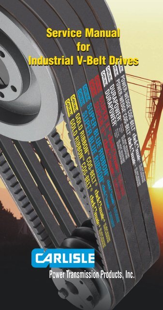
<strong>Service</strong> <strong>Manual</strong><strong>for</strong><strong>Industrial</strong> V-<strong>Belt</strong> <strong>Drives</strong>Power Transmission Products, Inc.
Table of ContentsThis CARLISLE V-BELT DRIVE SERVICE MANUAL hasbeen prepared with the double purpose of:Helping you AVOID V-belt drive problems by presenting astep-by-step V-belt replacement procedure–Section 1:Preventive Maintenance; and helping you SOLVE V-beltdrive problems by offering troubleshooting techniques–Section 2: Corrective Maintenance.SUBJECTPAGEV-BELT CONSTRUCTION ............................................................................2V-BELT DRIVE ADVANTAGES ......................................................................3SECTION 1–PREVENTIVE MAINTENANCE andINSTALLATION of V-BELT DRIVES ......................................4-9V-BELT INSTALLATION CHECK LIST ..........................................................9SECTION 2–CORRECTIVE MAINTENANCE andTROUBLESHOOTING of V-BELT DRIVES ......................10-35V-BELT DRIVE TROUBLESHOOTING GUIDE ......................................12-13TROUBLESHOOTING INSTALLATION PROBLEMS ............................14-21TROUBLESHOOTING SELECTION PROBLEMS ................................22-27TROUBLESHOOTING ENVIRONMENTAL PROBLEMS ......................28-31TROUBLESHOOTING DESIGN PROBLEMS........................................32-35INSTALLATION AND TAKE-UP DATA ........................................................36V-BELT TENSION TOOL ........................................................................37-38V-BELT DEFLECTION FORCE VALUES ....................................................39TOPICAL INDEX ..........................................................................................40 WARNING - SAFETY NOTEFailure to follow recommended application in<strong>for</strong>mation and recommended procedures <strong>for</strong>installation, care, maintenance and storage of products may result in failure to per<strong>for</strong>m properlyand may result in damage to property and serious bodily injury. Make sure that product selected<strong>for</strong> any application is recommended <strong>for</strong> that service. Contact Carlisle or your Carlisle distributor<strong>for</strong> assistance or specific recommendations.1
V-<strong>Belt</strong> ConstructionWrapped <strong>Belt</strong> Raw Edge ® Cog-<strong>Belt</strong> ®11223443Be<strong>for</strong>e we talk about “Avoiding Problems” and “SolvingProblems”, let’s take a brief look at how V-belts areconstructed.There are basically two types of construction. One has a fabric coversurrounding it; the other–usually rated higher in horsepower–is made in araw edge, cogged construction.Wrapped <strong>Belt</strong>1. Cover–Woven cotton fabricimpregnated with neoprene.2. Tension Section–Synthetic rubberspecially compounded to stretchas belt bends around sheaves.3. Cords–High-strength, syntheticfiber cords carry the horsepowerload and minimize stretching.4. Compression Section–Syntheticrubber compounded to supportcords evenly and compress whilebending around sheaves.Raw Edge ® Cog-<strong>Belt</strong> ®1. Tension Section–Speciallywoven stress-relieved fabricstretches up to 176% more thanordinary bias-cut fabric.2. Cords–Synthetic Hi-Moduluscords <strong>for</strong>m the strength memberto carry high loads with minimumstretching.3. Compression Section–ExclusiveStiflex ® rubber compounds andprecision molded cogs increaseflexibility while supporting cordsevenly.4. Raw Edge ® Sidewalls–Provideuni<strong>for</strong>m, anti-slip surface, greaterflexibility and allows more cordwidth.2
Section 1PreventiveMaintenanceand Installationof V-<strong>Belt</strong> <strong>Drives</strong>You will notice Reference KeyNumbers (such as A -1)appearthroughout this section. These referto a more detailed discussion withillustrations relating to the subject inSection 2 (Corrective Maintenanceand Troubleshooting).Safety FirstBe<strong>for</strong>e doing any maintenance work on power drives, be sure the controllingswitch is in the OFF position, locked out and tagged. Follow your plant’ssafety rules.4
Preventive Maintenanceand Installation of V-<strong>Belt</strong> <strong>Drives</strong>Relieve <strong>Belt</strong> TensionA -1After removing the drive guard,loosen the drive take-up and movethe sheaves closer together tofacilitate the removal of all old belts,and to insure installation of the newbelts without damage.Inspect Drive ElementsA -1 A -6This is a good time to service thetake-up rails by removing any rustand dirt, and lubricating as necessaryso tensioning of the new belts will gosmoothly and easily. You now alsohave an excellent opportunity toinspect and replace faulty or damagedmachine elements such as wornbearings and bent shafts.This procedure not only reduces thelikelihood of future mechanical trouble,but insures maximum service fromthe new belts you are about to install.Sheaves should be carefully cleanedof any rust and <strong>for</strong>eign material. Awire brush followed up with a shopcloth will usually do the job.5
Section 1Inspect SheavesA -4 A -9Sheave condition and alignment arevital to V-belt life and per<strong>for</strong>mance.New V-belts should never be installedwithout a careful and thoroughinspection of the sheaves involved.Particular attention should be givento these conditions:a. Worn Groove Sidewallsb. Shiny Sheave Groove Bottomc. Wobbling Sheavesd. Damaged SheavesShiny Sheave Groove BottomWorn Groove SidewallsWobbling SheavesDamaged SheavesAlign Sheaves (Preliminary)A -3 A -5Alignment should be given preliminary consideration at this time.Check to make sure that:a. The shaft of the DriveR and the DriveN sheaves are parallel,horizontally and vertically.b. The DriveR and DriveN sheaves are in a straight line.c. Both sheaves are properly mounted and as near to the bearingsas practical.6
Preventive Maintenanceand Installation of V-<strong>Belt</strong> <strong>Drives</strong>Select Replacement <strong>Belt</strong>sB -1 B -2 B -3 B -4After you have made any necessary corrections in your V-belt drive elements,the next step is the selection of the right replacement belts.In replacing sets of V-belts, here are some Very Important Reminders:• NEVER MIX NEW AND USED BELTS ON A DRIVE.• NEVER MIX BELTS FROM MORE THAN ONE MANUFACTURER.• ALWAYS REPLACE WITH THE RIGHT TYPE OF V-BELT.• ALWAYS OBSERVE V-BELT MATCHING LIMITS.Installing New <strong>Belt</strong>sA -1Place the new belts on the sheaves,and be sure that the slack of eachbelt is on the same side. You can dothis by pressing the belts with yourhand to bring the slack on one sideof the drive. Loosening the drivetake-up in advance makes this easy.RightDo not <strong>for</strong>ce the belts on thesheaves by using a pry bar or byrolling the sheaves. Now, movesheaves apart until the belts areseated in the grooves, and makepreliminary tightening of the drive,just until the slack is taken up.Wrong7
Section 1Apply TensionA -7 A -8All V-belt drives must operate under proper tension to produce the wedgingaction of the belt against the groove sidewall. A well-established rule ofthumb is that the best tension <strong>for</strong> a V-belt drive is the LEAST tension atwhich the drive will not slip under peak load.Most V-belt problems are due toimproper tensioning. Several tools andmethods are available to insure propertensioning. A simple and easy to useoption is the Tension-Finder availableonly from Carlisle.Run the drive <strong>for</strong> about 15 minutes.Then apply full load and check <strong>for</strong>slipping. Should slipping occur, further tension should be applied.After the drive has operated under load long enough <strong>for</strong> the belts tobecome seated and adjusted (approximately 24 hours), it is a good idea tomake a final tension inspection.For a complete discussion on tensioning and slippage, refer to Section 2A -7, in this manual.You have now completed a practical procedure <strong>for</strong> replacing V-belts thatshould help you AVOID problems with your V-belt drives. The check list onpage 9 serves to summarize the points discussed in this section.Check Sheave Alignment (Final)A -3One of the advantages of V-belt drives is the fact that perfect alignment ofsheaves is not critical to the operation of the drive–V-belts toleratemis-alignment of up to 1/16 inch per 12 inches of shaft center distance.However, the closer you can come to perfect alignment, the better.Laser AlignmentA -3Use a laser alignment tool or straight edge to check alignment. The straightedge should make contact at four distinct points along the outside perimeterof both sheaves.Contact pointsStraight edgeRefer to Section 2,procedures.ALaser alignment tool-3, <strong>for</strong> complete discussion of proper alignmentNote: Sheaves should always be mounted as close to the bearings aspractical to avoid excessive loads on bearings and shafts.8
Preventive Maintenanceand Installation of V-<strong>Belt</strong> <strong>Drives</strong>V-<strong>Belt</strong> Installation Check List1. Cut off and lock out power source.Observe all other safety procedures.2. Remove belt guard.3. Loosen motor mounts.4. Shorten center distance.5. Remove old belts.6. Inspect belt wear patterns <strong>for</strong> possibletroubleshooting.7. Inspect drive elements–bearings,shaft, etc.8. Inspect sheaves <strong>for</strong> wear and clean.9. Check sheave alignment. (preliminary) 10. Select proper replacement belts. 11. Install new belts. 12. Tension belts. 13. Check sheave alignment. (final) 14. Replace guard. 15. Start drive (look & listen). 16. Re-tension after 24 hours.9
Section 2CorrectiveMaintenanceand Troubleshootingof V-<strong>Belt</strong> <strong>Drives</strong>The first section of this V-<strong>Belt</strong><strong>Service</strong> <strong>Manual</strong> outlined a step-bystepprocedure <strong>for</strong> the installation ofreplacement V-belts to help youprevent V-belt maintenance problems.The reason behind these steps isalso fundamental in the daily inspectionand maintenance of V-beltdrives. Watching and listening willalert you to warning signs of trouble,since one of the greatest advantagesof V-belt drives is the fact that beltsand sheaves wear gradually. Youcan spot potential problems in timeto arrange a short, scheduled maintenancedown-time instead of experiencinga longer, costly interruptionof production when unexpectedtrouble occurs.V-belts may be thought of as beingmuch like electrical fuses–theirunexpected failure is usually a signalthat something else in the system iswrong. Even their patterns of gradualwear can often indicate conditionsneeding corrections or improvement.10
Corrective Maintenanceand Troubleshooting of V-<strong>Belt</strong> <strong>Drives</strong>How to correct maintenance problems by using Carlisle’sQuick Reference Troubleshooting GuideThe V-<strong>Belt</strong> Drive Troubleshooting Guide presented on the following pagesrepresents knowledge acquired by Carlisle in the development and manufactureof V-belts <strong>for</strong> almost 100 years.This quick-reference guide lists the most common symptoms or warningsigns of drive problems and then indicates possible causes.Each possible cause is further referenced by a key number (such as A -1)which indicates where you may find the cure in a more detailed discussionof the subject in this section of the manual.These discussions are grouped into four major sections:ATroubleshooting INSTALLATION ProblemsBTroubleshooting SELECTION ProblemsCTroubleshooting ENVIRONMENTAL ProblemsDTroubleshooting DRIVE DESIGN ProblemsPractical, non-technical troubleshooting tips are included to help you toquickly identify and correct suspected problems.11
Corrective Maintenanceand Troubleshooting of V-<strong>Belt</strong> <strong>Drives</strong>CURESSYMPTOMSCAUSESA-1A-2A-3A-4A-5<strong>Belt</strong>s Pried On Or Misplaced Slack<strong>Belt</strong>s Rubbing GuardSheaves MisalignedWorn Or Damaged SheavesSheaves Too Far From BearingRapid Sidewall Wear● ● ❉Worn Cover On Back❉●<strong>Belt</strong> Turns Over Or Jumps Off Sheave●●<strong>Belt</strong> Soft, Swollen<strong>Belt</strong> Slips, Squeals (Spin Burn)❉<strong>Belt</strong> Cover Split❉Underside CrackedTie-Band Damaged●● ● ❉Repeated Breakage●<strong>Belt</strong>s Ride Too High<strong>Belt</strong>s BottomingRepeated Take-up Necessary<strong>Belt</strong>s Vibrate Excessively Or Appear Mismatched●❉●●Bearings Are HotShafts Whip Or BendCracked BushingsSheave Wobble●●●●●●❉ Indicates most common causes ● Indicates other possible causes12
Poor Bearing Or Shaft ConditionInsufficient TensionExcessive TensionImproper Sheave Installation<strong>Belt</strong>s Worn (Normal <strong>Service</strong> Life)Wrong <strong>Belt</strong> Cross-Section Or TypeMismatched <strong>Belt</strong>s Or Mixed BrandsMachine-Induced Impulse Or ShockImproper Or Prolonged StorageExcessive HeatExcessive Oil Or GreaseUse of <strong>Belt</strong> DressingAbrasive EnvironmentForeign Objects In GroovesExcessive MoistureOverloaded Drive/UnderbeltingDrive Seriously OverbeltedSheaves Too SmallInsufficient Wrap On Small SheaveBackside IdlerHarmonicsA-6A-7A-8A-9B-1B-2B-3B-4C-1C-2C-3C-4C-5C-6C-7D-1D-2D-3D-4D-5D-6● ● ● ● ● ● ● ●●● ● ❉ ●❉●❉ ● ● ● ● ●●● ● ❉ ❉ ❉●❉● ● ● ❉❉●●●● ● ❉● ● ● ❉ ●●● ❉ ● ● ●● ❉ ● ●❉●❉13
TroubleshootingInstallationProblemsAs pointed out in Section 1 of thismanual, preventive maintenance byusing proper installation techniquesis important <strong>for</strong> long, trouble-freeV-belt service.Occasionally, however, you will findit necessary to correct problemscaused by improper installation.This section deals with theseproblems and troubleshootingprocedures.14
Troubleshooting Installation ProblemsA -1 Prying or <strong>for</strong>cing V-belts ontothe sheaves can, and usually does,break some of the load-carryingtensile cords (see photo on page 7,Section 1). When this happens, thebelt may either break or turn over inthe groove, usually within the firstfew minutes of operation. Thismethod of installation may beevidenced by a rupture or split in thewrapped cover of the belt, causedby the prying tool or sheave edge.Broken cords are easily identifiableon raw-edge V-belts, because it isusually the edge cords that breakfirst.Misplaced Slack can also causebelt breakage, again usually onstartup. This occurs on multiple-beltdrives when all of the belt slack isnot brought to the same side of thedrive be<strong>for</strong>e tensioning. If somebelts are tight on one side, andothers are tight on the other side,the heavy shock load of starting willbe borne by only some of the belts,thus weakening or breaking theload-carrying cords.Ruptured CoverA -2 <strong>Belt</strong>s rubbing against the metalguard or other obstruction will beevidenced by cut or worn fabric on theback or upper edge of the V-belt. Oftenjust replacing missing bolts in guardbrackets will remedy this situation.Fabric Worn onBackside15
AA -3 Misaligned sheaves cancause rapid wear of the V-belt sidewalls,considerably shortening servicelife of both belts and sheaves.Mis-alignment can also causeseparation of the tie-band on bandedbelts, or apparent mismatching ofindividual belts. V-belt sheave alignmentshould be within a tolerance of1/16” per 12” of drive centerdistance.The three basic types of sheaveand shaft misalignment are shownbelow, with suggested methods <strong>for</strong>checking and correcting each type.Note that all 3 types may exist atthe same time. Alignment should bechecked and corrected in the ordergiven.Sidewall WearHorizontal VerticalAngular Angular Parallel16
Troubleshooting Installation Problems1. Horizontal Angular (shafts in same horizontal plane but not parallel)To Check: Use straightedge or string near sheave centers.To Correct: Loosen motor mounting bolts and rotate motor until all 4points touch straightedge.2. Vertical Angular (shafts in same vertical plane but not parallel)To Check: Place straightedge about 4 radius from the outside diameterof both sheaves as shown 1. Repeat on opposite side of shaft 2.Straightedge should touch 4 points indicated in each position.To Correct: Use shims under motor base in front or rear of motor,depending on type of correction required.3. Parallel (shafts are parallel; sheaves not in line)To Check: Use straightedge or string near sheave centers.To Correct: Loosen sheave so it slides easily on shaft until all 4 pointstouch straightedge. Retighten sheave in position. Important: Sheaveshould be mounted as close to bearing as possible to reduce overhungload on bearing. Re-locate equipment if necessary.17
AA -4 Worn or damaged sheaves are an even greater cause of rapid beltwear, slippage and vibration. Badly worn sheaves can cause over-tensioningof the drive to prevent slippage, indirectly causing over-heated bearings andshaft damage. If pieces of the sheave flange are missing, it will result inbadly worn sidewalls of the belt, and the resulting sheave imbalance candamage bearings and create a safety hazard. When only some of thegrooves are worn more than others, the effect is that the belts appear to bemis-matched. It also causes “differential driving,” where only some of thebelts are carrying the entire load of the drive.In the case of banded belts, worn grooves cause the belts to ride too low inthe grooves, thus causing the tie-band to wear against the sheave flangesbetween the grooves. In severe cases, this can have the same effect as acircular blade, cutting the band and separating the belts.Sheave templates are available from your Carlisle distributor, which can beused to check grooves accurately <strong>for</strong> wear. A flashlight held behind the templatewhen placed in the groove will help you to observe the amount ofwear. “Dishing” should not exceed 1/32” <strong>for</strong> individual V-belts, or 1/64” <strong>for</strong>banded V-belts. A shiny groove bottom is a sign that the belt or sheave, orboth are badly worn and the belt is bottoming in the groove. Worn sheavesor shiny sheave groove bottoms will show up first on the smaller sheave.The cost of replacing a worn sheave will be more than recovered in longerV-belt life, reduced maintenance and downtime.Worn SidewallsCut Tie-BandProper Position of <strong>Belt</strong> inSheaveBottoming and Dishing of<strong>Belt</strong> in Sheave18
Troubleshooting Installation ProblemsA -5 Sheaves mounted too far from the bearing cause excessive overhungload on the bearing and overheating. This can also cause shafting towhip, bend or break. Sheaves should be mounted as close as possible tothe bearing. If this affects alignment severely, it may be necessary to relocatethe equipment to stay within alignment limits of 1/16” per 12” of shaftcenter-to-center distance.A -6 Bearing condition and normal wear may well be the cause of overheating,rather than belt tension. They should be inspected <strong>for</strong> proper lubricationand wear according to the specifications of the bearing or equipment manufacturer.Shaft condition should also be checked and replaced if necessary,as bent shafts can be detrimental to bearings, belts and sheaves, as well asbeing a safety hazard due to the imbalance created. Sheave “wobble” maybe caused by bent shafts.A -7 Insufficient belt tension vies closely with worn sheave grooves asthe leading cause of V-belt slippage and other problems. This is often evidencedby “spin burn”. The easiest and most practical way <strong>for</strong> maintenancepersonnel to judge proper belt tension is by the “SST” method–Sight, Soundand Touch.Spin Burn19
ASight–While the drive is operating,look <strong>for</strong> a slight “bow” or “sag” inthe slack side of the belts. This isnormal, and should appear morenoticeable under heavy load, suchas at startup or during the loadcycles of an air compressor, <strong>for</strong>instance. Check the sheavegrooves <strong>for</strong> wear.Sound–Properly designed V-beltdrives should not squeal or howlunder peak load conditions, suchas on startup of a centrifugal fan. Ifnecessary, stop the drive, then startit again. If a squeal is heard, thebelts should be tightened just to thepoint where they do not squealunder peak load. Newly installedbelts require about 24 hours tobecome fully seated in the grooves,so a little extra tension and arecheck the next day are called <strong>for</strong>.Touch–V-belts don’t always squealwhen they are slipping. If slippageis suspected, a sure way of determiningit is by stopping the drive(lock it out!) and placing your barefinger against the inside of asheave groove. If slippage is present,it will generate enough heat sothat you can’t keep you finger onthe groove. If this is true, and thereis no outside heat source, then thedrive is probably slipping.Assuming no sheave wear, thedrive should be tightened. If thesheave is worn, replace the sheaveand tension normally. Use thevarious tensioning tools that areavailable from Carlisle to assureproper tensioning.20
Troubleshooting Installation ProblemsA -8 Excessive tension on V-belts can be even more detrimental than toolittle tension, affecting not only the belts, but also bearings and shafts.Again, the best rule is to apply only enough tension on the belts to keepthem from slipping during startup or peak loading. Some indicators ofexcessive tensioning (but not always) are:• Repeated belt breakage• Excessive vibration• Overheated bearings• Whipping or bent shaftsA -9 Improper sheave and bushing installation can result in sheave“wobble” as well as causing bushings or sheave hubs to crack. Wheninstalling split-tapered bushings such as QD ® or Taper-Lock types, alwaysfollow manufacturer’s instructions.It is important to never lubricate the tapered surfaces be<strong>for</strong>e installing. Thelubrication will permit recommended torque wrench values to increase theactual <strong>for</strong>ce on the bushing and hub. This usually results in cracking of thebushings at the bolt hole or keyway.On flanged bushing types, the flange should never be brought up flush withthe sheave hub face. A small gap between the two surfaces is normal.When removing split-tapered bushings, start at the jack-screw holeopposite the split, to avoid cracking the bushing.Cracked BushingRecommened Wrench Torque Values To Use In Tightening QD BushingsFoot PoundsCap ScrewTorque WrenchBushing Size Size & Thread Normal Applications*QT 1/4-1 9JA No. 10-24 5SH-SDS-SD 1/4-20 9SK 5/16-18 15SF 3/8-16 30E 1/2-13 60F 9/16-12 110J 5/8-11 135M 3/4-10 225N 7/8-9 300P 1-8 450W 1-1/8-7 600S 1-1/4-7 750* For severe (rock-crusher type applications) these values can be increased by a maximumof 50%. On severe applications the bolt torque should be rechecked at periodic intervalsduring operation.21
BTroubleshootingSelection ProblemsThe array of V-belt types, crosssectionsand lengths on the markettoday are all part of technologicalef<strong>for</strong>ts to provide more efficient,cost-saving answers to your driverequirements.This category is intended to pointout how you can be sure of applyingthe best Carlisle V-belt type to yourapplications.22
Troubleshooting Selection ProblemsB -1 Worn V-belts may have gotten that way simply because they havedelivered the service life built into them. Carlisle, like other manufacturers,strives to build V-belts with a “balanced” construction, so each element ofthe belt will last as long as all other elements. But the wide variety of industrialapplications, environmental conditions and maintenance practices makesthis impossible to achieve. However, the expected life of an industrial V-belton a properly designed drive is 3 years.B -2 Using the wrong V-belt cross-section or type can create problems<strong>for</strong> you...and it’s not hard to do, since many have similar dimensions. Forexample, the following Carlisle V-belts have approximately the same topwidth (5/8”) and length (85” O.C.):And yet, the horsepower ratings of these belts range from as little as 2.2 HPper belt to as much as 11.9 HP per belt. on a 5” diameter sheave and 1750RPM motor!5/8"5L11/32"5L850 Durapower®Light Duty FHP V-<strong>Belt</strong>5/8"58X11/32"58X850 XDV® Premium V-<strong>Belt</strong>21/32"BP7/16"BP82 Super Blue Ribbon® V-<strong>Belt</strong>21/32"7/16"BX82 Gold Ribbon Cog-<strong>Belt</strong>®5/8"17/32"5VX850 Power-Wedge® Cog-<strong>Belt</strong>®23
BA V-belt survey of your drives by a Carlisle Certified Drive Specialist canassure you of using the correct V-belt. This service may be obtained bycontacting your Carlisle Authorized Stocking Distributor. He maintains a fulland convenient inventory of replacement belts and sheaves, and standsready to assist you in selecting the proper size and type <strong>for</strong> each application.Carlisle’s <strong>Industrial</strong> Power Transmission catalog lists all types and sizes ofstock industrial belts and sheaves. However, the following suggestions willcover the most serious selection problems:DO match the correct belt cross-section to the sheave groove. (A-A, B-B,5V-5V, etc.)DON’T use “B” section belts in “5V” grooves, or vice-versa. Check thesheave number stamped on the rim if in doubt.DON’T replace “A” or “B” heavy duty V-belts with “4L” or “5L” light duty(FHP) V-belts. FHP belts are built <strong>for</strong> Fractional Horsepower applications,and usually run singly. Most multiple drives require heavy duty belts.DO use V-belts marked “Oil and Heat Resistant” where oil or heat is present.The Carlisle Gold Ribbon Cog-<strong>Belt</strong> and Power-Wedge Cog-<strong>Belt</strong> offermaximum heat and oil resistance–see key numbers C-2 and C-3DO insist on a belt labeled “Static-dissipating” on drives operating inhazardous atmospheres.DO use banded V-belts where vibration or shock loads can cause belts toturn over or jump out of the sheave grooves.DO use matched sets from the same manufacturer (see key number B -3)DON’T mix old and new belts on a drive. They cannot be matched.GOLD RIBBON COG-BELT®GOLD RIBBON COG-BELT®OIL HEAT RESISTANTSTATIC DISSIPATINGOIL HEAT RESISTANTSTATIC DISSIPATINGMADE INU.S.A.MADE INU.S.A.BX62BX62B -3 Mismatched belts or mixed brands from different manufacturerscannot be matched together, and will not deliver the service life they should.Although all manufacturers use similar belt numbering systems, differentbrands with the same number will differ slightly in dimensions and are notcapable of being mixed in a set. Also, construction differences cause themto ride differently in the grooves, and to stretch differently.It should be noted that the majority of complaints regarding belt matchingare found to be due to other causes, such as misalignment and sheave wear.These factors should always be checked if belts seem to be mismatched.Carlisle belts branded with the Chek-Mate TM logo do not require the use ofmatching codes, but all belts in the set must bear this symbol.24
Troubleshooting Selection ProblemsB -4 Machine-induced vibration or shock loads frequently can causeV-belts to whip or even jump off the drive, creating a safety hazard, and ofcourse, damaging the belts.On multiple-belt drives, this whipping can be reduced or eliminated by usingbanded V-belts. A banded V-belt consists of from 2 to 5 individual V-beltsjoined together with a bonded, rein<strong>for</strong>ced tie-band (see illustration).These belts will ride slightly higher in the sheave grooves to provide clearancebetween the band and the sheave flange. Because of this, sheave groovesshould not be worn or “dished-out” more than 1/64”. Also, because they arebanded together, alignment of the sheaves is somewhat more critical.<strong>Belt</strong>s riding slightly higherin the sheave grooves.(The chart on the next page will be helpful in selecting the best Carlislebelt <strong>for</strong> an application.)25
BV-<strong>Belt</strong> Selection GuideMaximumGeneric <strong>Belt</strong> Type Normal <strong>Belt</strong> SpeedCarlisle Brand (Cross-Sections) HP Range (FT/Min) (1)Super Blue Classical Multiple 1-500 6500Ribbon (A, B, C, D)Super ll Classical Multiple 1-500 6500(A, B, C, D)Gold Ribbon Classical Cogged 1-500 6500Cog-<strong>Belt</strong>Multiple (AX, BX, CX, DX)Super Narrow Multiple 1-1000 6500Power-Wedge (3V, 5V, 8V)Power-Wedge Narrow Cogged 1-600 6500Cog-<strong>Belt</strong>Multiple (3VX, 5VX)Super Classical Banded 1-500 6500Vee-Band(RB, RC, RD)Gold Ribbon Classical Cogged Banded 1-500 6500Cog-Band(Premium HP)(RBX, RCX, RDX)Wedge-Band Narrow Banded 1-1000 6500(R3V, R5V, R8V)Double Double-V <strong>Belt</strong>s 1-200 6500Angle(AA, BB, CC, DD)Variable Speed Variable Speed 21-100 6500Cog-<strong>Belt</strong>(1228V-6136V)Vee-Rib V-Ribbed 4-500 6000(J, L, M)Thoro-Twist Link (Segmented) 1-300 5000(3LTwist, ATwist, BTwist, CTwist)(1000 min.)Durapower FHP Light Duty 6500(2L, 3L, 4L, 5L)Durapower ll FHP Light Duty 6500(2L, 3L, 4L, 5L)XDV Premium FHP Light Duty 6500(38X, 48X, 58X)Notes: (1) Normally limited by sheave materials. (2) Expect little or no life loss due to heat.26
Troubleshooting Selection ProblemsNormalTemp. Range Oil/Heat Static(˚F) (2) Resistance Dissipating General ApplicationMin. Max.-35 120 Good ✔ General-Purpose Heavy Duty<strong>Industrial</strong> <strong>Drives</strong>.-35 120 Good ✔ General-Purpose Heavy Duty<strong>Industrial</strong> <strong>Drives</strong>.-35 130 Excellent ✔ Longer Life, High Efficiency,Small Diameters.-35 130 Very ✔ High-Per<strong>for</strong>mance, CompactGood<strong>Industrial</strong> <strong>Drives</strong>, Long C.D.-35 130 Excellent ✔ High-Per<strong>for</strong>mance, Compact<strong>Industrial</strong> <strong>Drives</strong>, Short C.D.-35 120 Good ✔ Reduces <strong>Belt</strong> Whip, Turnoveron Pulsating, Surge Loads.-35 130 Excellent ✔ Longer Life, High Efficiency,Reduces <strong>Belt</strong> Whip, Turnoveron Pulsating, Surge Loads-35 130 Very ✔ Reduces <strong>Belt</strong> Whip, TurnoverGoodon Pulsating, Surge Loads-35 120 Good Special Order Serpentine <strong>Drives</strong>-35 130 Excellent ✔ Wide-Range VariableSheaves-35 130 Very Small Diameters, High SpeedGood No Ratios, Compact-35 130 Excellent No Emergency ReplacementFixed Center Distance-35 120 Fair ✔ Light Duty <strong>Drives</strong>Using a Single <strong>Belt</strong>-35 120 Fair ✔ Light Duty <strong>Drives</strong>Using a Single <strong>Belt</strong>-35 130 Very Longer Life on FHP <strong>Drives</strong>,Good No Clutching Lawn/Garden<strong>Drives</strong>Available inconstruction27
CTroubleshootingEnvironmentalProblems“Environmental Protection” can beas important <strong>for</strong> a V-belt as <strong>for</strong>humans. This section deals with theeffect of adverse environmentalconditions on V-belts, and how youcan minimize these effects.28
TroubleshootingEnvironmental ProblemsC -1 Improper or prolonged storage can reduce service life considerably.V-belts should be stored in a cool, dry place with no direct sunlight. On shelvesin boxes or piles, the stack should be small enough to avoid excess weightand distortion on the bottom belts. On pegs, the longer belts should be coiledin loops of suitable size to prevent distortion from the weight of the belt.The following guide provided by the RMA should be followed <strong>for</strong> optimumconditions:Guide to Maximum Number ofCoilings of V-<strong>Belt</strong>s of Storage<strong>Belt</strong> <strong>Belt</strong> Length Number NumberCross Section (Inches) of Coilings* of Loops*Under 60.0 None 1A,AA,**3V 60.0 to 120.0 1 3and B 120.0 to 180.0 2 5180.0 and up 3 7Under 75.0 None 1BB,**C, 75.0 to 144.0 1 3and 5V 144.0 to 240.0 2 5240.0 and up 3 7Under 120.0 None 1120.0 to 240.0 1 3D 240.0 to 330.0 2 5330.0 to 420.0 3 7420.0 and up 4 9Under 180.0 None 1180.0 to 270.0 1 3E and 8V 270.0 to 390.0 2 5390.0 to 480.0 3 7480.0 and up 4 9*One coiling results in three loops; two coilings result in five loops, etc.**“AA” and “BB” are known as “double angle” or “hexagonal” V-belts.The pegs should be crescent shaped in cross-section to avoid compressionset dents in the belts from sharp corners and the pegs should be sufficientlylarge in cross-section to avoid compression setting into sharp bends resultingfrom the weight of the hanging belts.It is recognized that belts are sometimes coiled in smaller loops <strong>for</strong> packaging<strong>for</strong> shipment than indicated in the above table, but such packaging shouldnot be <strong>for</strong> prolonged storage.29
CC -2 Excessive heatStandard construction V-belts (such as Carlisle’s Super Blue Ribbon) arecompounded <strong>for</strong> moderate resistance, and should give adequate serviceunder normal conditions.<strong>Belt</strong> temperature (not ambient or surrounding air temperature) is the determiningfactor when heat is a suspected cause of short belt life.Tests have shown that the service life of a V-belt is cut in half <strong>for</strong> every18˚F raise in belt temperature.Troubleshooting <strong>Belt</strong> TemperatureA good general rule <strong>for</strong> checking belt temperature without sophisticatedinstruments is to stop the drive (lock it out!) and touch the belt with your hand.If you can grasp if firmly <strong>for</strong> at least 5 seconds, the belt temperature isprobably not over 140˚F and there<strong>for</strong>e not beyond the operating range <strong>for</strong>most V-belts. However, if you can’t hold it <strong>for</strong> at least 5 seconds, the belttemperature is probably well over 140˚F, and heat is contributing to shortbelt life.Further evidence of heat may be the appearance of small cracks on theunderside of the belt.What to do about excessive heat:1. Check <strong>for</strong> slippage (see key number A -7).2. Ventilate the drive or shield from heat source.3. Replace belts with specially compounded heat-resistant belts (such asCarlisle’s Gold Ribbon or Power-Wedge Cog-<strong>Belt</strong>).Heat CracksC -3 Excessive oil or greaseStandard construction V-belts (such as Carlisle’s Super Blue Ribbon) arecompounded <strong>for</strong> moderate grease and oil resistance. However, an excessiveamount can cause softening, swelling and deterioration of the rubber compounds,as well as slippage.What to do about oil or grease:1. When there is occasional exposure from spillage or leakage, the beltsand sheave grooves should be cleaned with a mixture of detergent andwater–after the drive has been locked out and cause of leakage corrected.2. When belts cannot be protected from oil, specially compounded oilresistantV-belts (such as Carlisle’s Gold Ribbon or Power-Wedge Cog-<strong>Belt</strong>) should be used.30
TroubleshootingEnvironmental ProblemsC -4 Never apply so-called “beltdressings” to V-belts. These compoundsare usually made from apetroleum derivative and can have adestructive effect on rubber compoundsand other components of thebelt. If belts slip, check <strong>for</strong> adequatetension and/or worn sheave grooves(see A -4, A -7).C -5 Abrasive conditions fromsand, dust or grit can acceleratewear of both belts and sheaves.This is especially true when slippageis present. <strong>Belt</strong> selection can be animportant factor. Experience hasshown that raw-edge constructionsreduce this wear because theyreduce the “sandpaper-effect” causedby slippage. <strong>Drives</strong> should be wellshieldedagainst excessive abrasiveparticles as much as possible.C -6 Foreign objects, such as woodchips, can create havoc with V-beltdrives. <strong>Belt</strong> breakage and turnoverare the most common symptoms.Shielding the drive is a necessity.<strong>Belt</strong> guards with expanded metalscreening are often used, but ventilationis sometimes sacrificed, possiblyrequiring additional cooling. Bandingbelts are often effective, since theyeliminate belt turnover.Abrasive WearC -7 Excessive moisture canpenetrate the fabric covering of aV-belt, causing deterioration. Inaddition, a large amount of watercan reduce friction and cause slippage.<strong>Belt</strong> drives should be protectedas much as possible when usedoutside or when subject to sprayfrom washdown hoses, etc. <strong>Belt</strong>tension should be inspected regularly.31
DTroubleshootingDesign ProblemsWhen normal corrective measuresas discussed in the previous sectionsdo not seem to produce the desiredresults, an inherent design problemmay be the culprit. The solutions tothese are best left up to the plantengineering department or a CertifiedDrive Specialist. However, the discussionpresented in this section willhelp identify symptoms caused bydesign problems.32
Troubleshooting Design ProblemsD -1 Underbelting a drive, (usingfewer belts than recommended bygood design practice) results inexcessive tension in each belt onthe drive.This is commonly evidenced byexcessive stretching which requiresfrequent take-ups to prevent slippage.Another warning sign can be repeatedbelt breakage.In many cases, underbelting can becorrected simply by using raw edge,cogged V-belts which have a higherhorsepower rating. When these areused, drives should be identified toassure that future replacements aremade with this type of belt.D -2 Drive overbelting, while usuallyresulting in longer V-belt life, can bejust as serious as underbelting. Thesymptoms most commonly foundare overheated bearings and bentshafts.When too many belts are on thedrive, the total tension can beexcessive when “table” values areused. On the other hand, when toofew belts are on the drive, tensionvalues from these tables may beinadequate.D -6 <strong>Belt</strong> Vibration, is anot-so-common problem resultingfrom tension harmonics. Sinceinduced vibration can be caused byseveral factors, this should bereferred to plant engineering.33
DD -3 When sheaves are too small <strong>for</strong> the belt cross-section, the belt flexesbeyond its normal limits. This is usually evidenced by cracks on the undersideof the belt. Table A indicates the minimum recommended sheave diameter<strong>for</strong> flexing each belt cross-section. In most cases, use of a raw-edge coggedbelt will improve service life greatly, due to its greater flexibility.Table A. Minimum Recommended Sheave and Idler DiametersV-<strong>Belt</strong> Minimum P.D. Minimum O.D.Cross Section Sheave or Inside Idler Flat Backside Idler*A, AP 3.0 4.5B, BP 5.0 7.5C, CP 9.0 13.5D, DP 13.0 19.5E, EP 21.0 31.5AX 2.6 4.0BX 4.0 6.0CX 7.0 10.5DX 11.0 16.53V 2.6 __3VX 2.2 __5V 7.0 __5VX 4.3 __8V 12.4 __8VX 11.2 __*Note: Backside Idlers are detrimental to V-belt service life.Another problem caused by sheaves that are too small is overheating ofmotor bearings, or even bent shafts. NEMA publishes minimum recommendedsheave diameters <strong>for</strong> use with electric motors to avoid excessive bearingloads. Table B shows these minimums <strong>for</strong> the most common motor types.General purpose motors having continuous time rating with the frame sizes,horsepower and speed ratings listed in the following are designed to operatewith V-belt sheaves within the limiting dimensions listed. Selection of V-beltsheave dimensions is made by the V-belt drive vendor and the motor purchaserbut, to assure satisfactory motor operation, the selected pitch diameter shallbe no smaller than the dimensions listed on the next page.34
Troubleshooting Design ProblemsTable B. Application of V-<strong>Belt</strong> Sheave Dimensions to General Purpose MotorsFrameNumberIntegral-Horsepower Motors–Polyphase IndcuctionHorsepower atSynchronous Speed, Rpm3600 1800 1200 900V-belt SheaveConventional NarrowA,B,C,D & E 3V,5V, & 8VMinimum MinimumPitch OutsideDiameter, Diameter,Inches Inches143T 12 1 w 2 2.2 2.2145T 2-3 12-2 1 w 2.4 2.4182T 3 3 12 1 2.4 2.4182T 5 … … … 2.6 2.4184T … … 2 12 2.4 2.4184T 5 … … … 2.6 2.4184T 72 5 … … 3.0 3.0213T 72-10 72 3 2 3.0 3.0215T 10 … 5 3 3.0 3.0215T 15 10 … … 3.8 3.8254T 15 … 72 5 3.8 3.8254T 20 15 … … 4.4 4.4256T 20-25 … 10 72 4.4 4.4256T … 20 … … 4.6 4.4284T … … 15 10 4.6 4.4284T … 25 … … 5.0 4.4286T … 30 20 15 5.4 5.2324T … 40 25 20 6.0 6.0326T … 50 30 25 6.8 6.8364T … … 40 30 6.8 6.8364T … 60 … … 7.4 7.4365T … … 50 40 8.2 8.2365T … 75 … … 9.0 8.6404T … … 60 … 9.0 8.0404T … … … 50 9.0 8.4404T … 100 … … 10.0 8.6405T … … 75 60 10.0 10.0405T … 100 … … 10.0 8.6405T … 125 … … 11.5 10.5444T … … 100 … 11.0 10.0444T … … … 75 10.5 9.5444T … 125 … … 11.0 9.5444T … 150 … … … 10.5445T … … 125 … 12.5 12.0445T … … … 100 12.5 12.0445T … 150 … … … 10.5445T … 200 … … … 13.2NEMA Standard, MG1-14.42D -4 Insufficient wrap on the small sheave can require excessive belt tensionto prevent slippage. This condition may require re-design, either using morebelts, increasing the center distance or using a backside idler with longer belts.This is again a matter <strong>for</strong> plant engineering.D -5 Backside idlers can create their own problems, because they cause V-beltsto bend opposite to the way they were designed. Care must be taken to seethat a backside idler is large enough in diameter to reduce harmful stresses,which often cause cracks on the underside of the belt. Table A (under D -3) alsoshows these minimum recommended diameters.Full technical in<strong>for</strong>mation regarding proper V-belt design can be found in theCarlisle Engineering Guide <strong>for</strong> <strong>Industrial</strong> V-<strong>Belt</strong> <strong>Drives</strong> available from yourCarlisle distributor.35
INSTALLATION AND TAKE-UP DATATABLE 3 POWER-WEDGE/SUPER POWER-WEDGE V-BELTS CENTERDISTANCE ALLOWANCE FOR INSTALLATION AND TAKE-UP (INCHES)For Take-UpStandard For Installation (Subtract)Length(Add)Designation3VX 3V 5VX 5V 8VX 8V All3V Banded 5V Banded 8V Banded CrossSections250 thru 475 0.5 1.2 — — — — 1.0500 thru 710 0.8 1.4 1.0 2.1 — — 1.2750 thru 1060 0.8 1.4 1.0 2.1 1.5 3.4 1.51120 thru 1250 0.8 1.4 1.0 2.1 1.5 3.4 1.81320 thru 1700 0.8 1.4 1.0 2. 1.5 3.4 2.21800 thru 2000 — — 1.0 2.1 1.8 3.6 2.52120 thru 2360 — — 1.2 2.4 1.8 3.6 3.02500 thru 2650 — — 1.2 2.4 1.8 3.6 3.22800 thru 3000 — — 1.2 2.4 1.8 3.6 3.53150 thru 3550 — — 1.2 2.4 2.0 4.0 4.03750 — — — — 2.0 4.0 4.54000 thru 5000 — — — — 2.0 4.0 5.5TABLE 4 CLASSICAL V-BELTS CENTERDISTANCE ALLOWANCE FOR INSTALLATION AND TAKE-UP (INCHES)For Take-UpStandard For Installation (Subtract)Length(Add)Designation A, AX B, BX BX & BP C, CX CX & CP DX DX & DP AllAP BP Banded CP Banded DP Banded CrossSections21 thru 35 0.75 1.00 1.50 — — — — 1.0036 thru 55 0.75 1.00 1.50 1.50 2.00 — — 1.5056 thru 85 0.75 1.25 1.60 1.50 2.00 — — 2.0086 thru 112 1.00 1.25 1.60 1.50 2.00 — — 2.50116 thru 144 1.00 1.25 180 1.50 12.10 2.00 2.90 3.00148 thru 180 — 1.25 1.80 2.00 2.20 2.00 3.00 3.50191 thru 210 — 1.50 1.90 2.00 2.30 2.00 3.20 4.00225 thru 240 — 1.50 2.00 2.00 2.50 2.50 3.20 4.50225 thru 300 — 1.50 2.20 2.00 2.50 2.50 3.50 5.00315 thru 390 — — — 2.00 2.70 2.50 3.60 6.00420 and over — — — 2.50 2.90 3.00 4.10 1.5% of <strong>Belt</strong>Length36
Tensioning–Carlisle V-<strong>Belt</strong> Tension ToolUser InstructionsThe Carlisle Tension-Finder can be used to tension individual belts orV-Bands.The Tension-Finder should be used only with Carlisle belt lines listed in Table 1.The Tension-Finder should NOT be used with aramid cord or glass cord belts.Use with these belts could result in damage to equipment.Warning!! Remove The Tension-Finderfrom the belt be<strong>for</strong>e starting the drive.ProcedureStep 1: Install belts loosely on the drive.Step 2: Apply enough tension to take the slack out of the belts.Step 3: Scribe a line on thebelt using the Tension-Finderas a square. (For cog beltssee the special instructions)Step 5: With the line in theStart Slot attach the spring tothe belt. Note: For cog beltsthe best place <strong>for</strong> the springmay be in a cog.(See specialinstructions)Step 7: Determine therequired slot <strong>for</strong> your drivefrom Table 1. Tighten the beltuntil the line has moved tothe designated slot. (In thispicture the line is in Slot 3.)Step 4: Place the Start Slotover the line.Step 6: Scribe a line at thespring end of the Tension-Finder. Use this line as areference point in case thespring slips off the belt.Step 8: Remove theTension-Finder from the belt,tighten mounting bolts, andreplace belt guards. You’reready to start the drive!Table 1: Recommended Tensioning SlotsSlot No.<strong>Belt</strong> Lines New <strong>Belt</strong> Used <strong>Belt</strong>AP, BP, CP, DP, RBP, RCP, RDPA, B, C 2 1AX, BX. CX, DX, RBX, RCX, RDX5V,8VR3V, R5V,R8V5VX, 8VX 3 2R3VX, R5VX,R5VLSPAX, SPBX, SPCXSee recommended slot no’s <strong>for</strong> table 1 page on (38)37
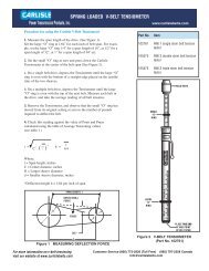
Tensioning–Carlisle V-<strong>Belt</strong> Tension Tool (cont)The recommended slot no's. in Table 1 will provide an adequate level ofbelt tension on average drives. If more tension is required go to a higherslot no. For less tension go to a lower slot no.Note: Slots 4 and 5 on the Tension-Finder are provided <strong>for</strong> drives wherethe values in Table 1 do not provide adequate tension. Please consultCarlisle Application Engineering be<strong>for</strong>e tensioning a drive to these slots.Warning!! Remove The Tension-Finderfrom the belt be<strong>for</strong>e starting the drive.Special Instructions For Cog <strong>Belt</strong>sIf the spring clip won’t sit securely on the flat area between cogs take thefollowing steps to scribe the line on the belt.Place the spring in a coggroove.Put a dot at the Start Slot.Be careful not to catch thepen in the slot--you may pullthe tip out of the pen.Scribe a line through the dot.The line should extendacross the width of theTension-Finder. Then goback to step 4 on page 37.Spring Loaded Tensiometer <strong>for</strong> V-<strong>Belt</strong>sUses a tensioning method based on the fact that the <strong>for</strong>cerequired to deflect a given span length by a given amountis related to the tension in the belt.Procedure <strong>for</strong> using the Carlisle V-<strong>Belt</strong> Tensiometer1. Measure the span length of the drive. (See Fig. 1).Set the large “O” ring at 1/64˝ <strong>for</strong> each inch of belt span. Forexample, set the large “O” ring 1/4˝ <strong>for</strong> a span length of 16˝,at 1/2˝ <strong>for</strong> a span length of 32˝, at 1˝ <strong>for</strong> a span length of 64˝etc.2. Set the small “O” ring at zero and press down the CarlisleTensiometer at the center of the belt span (See Fig. 2).a. On a single belt drive, depress the Tensiometer until thelarge “O” ring is even with the bottom of a straight edgeplaced on the outside rims of the two sheaves.b. On a multiple belt drive, depress the Tensiometer until thelarge “O” ring is even with the top of the next belt. Measureeach belt in the drive. and take the average reading of all belttensions.SMALL"O"RINGLARGE"O"RINGFig. 1DDEL. 1 INCHES 25 10 15 20 25 30 LBHOLDHEREPLACE THIS ENDAT MID-POINTOF BELT SPANSPAN LENGTH, LDEFLECTION FORCE,pDEFLECTION, qSd3. Remove the Tensiometer, and observe that the small “O”ring has moved from its original setting at zero to the numberof pounds required to deflect the belt.4. Check this reading against the value of the deflection <strong>for</strong>cein the V-<strong>Belt</strong> Tensioning table (page 39).Fig. 2C38
TensioningV-BELT TENSIONINGAVERAGE TENSIONING VALUES (RECOMMENDED MINIMUM FORCE PER BELT)V-<strong>Belt</strong> V-<strong>Belt</strong> Small Sheave Deflection Force <strong>for</strong> Drive Speed Ratio (lbs.)Type Section Speed Range Diameter 1.00 1.5 2.0 4.0 & over1800-3600 3.0 2.0 2.3 2.4 3.3A 1800-3600 4.0 2.6 2.8 3.0 3.3Super ll AP 1800-3600 5.0 3.0 3.3 3.4 3.71800-3600 7.0 3.5 3.7 3.8 4.3B1200-1800 4.6 3.7 4.3 4.5 5.01200-1800 5.0 4.1 4.6 4.8 5.6BP 1200-1800 6.0 4.8 5.3 5.5 6.31200-1800 8.0 5.7 6.2 6.4 7.2900-1800 7.0 6.5 7.0 8.0 9.0CSuper900-1800 9.0 8.0 9.0 10.0 11.0CPBlue Ribbon900-1800 12.0 10.0 11.0 12.0 13.0700-1500 16.0 12.0 13.0 13.0 14.0900-1500 12.0 13.0 15.0 16.0 17.0DP900-1500 15.0 16.0 18.0 19.0 21.0700-1200 18.0 19.0 21.0 22.0 24.0700-1200 22.0 22.0 23.0 24.0 26.01800-3600 3.0 2.5 2.8 3.0 3.3AX1800-3600 4.0 3.3 3.6 3.8 4.21800-3600 5.0 3.7 4.1 4.3 4.61800-3600 7.0 4.3 4.6 4.8 5.31200-1800 4.6 5.2 5.8 6.0 6.9BX1200-1800 5.0 5.4 6.0 6.3 7.11200-1800 6.0 6.0 6.4 6.7 7.7Gold Ribbon 1200-1800 8.0 6.6 7.1 7.5 8.2Cog <strong>Belt</strong> 900-1800 7.0 10.0 11.0 12.0 13.0CX900-1800 9.0 11.0 12.0 13.0 14.0900-1800 12.0 12.0 13.0 13.0 14.0700-1500 16.0 13.0 14.0 14.0 15.0900-1500 12.0 16.0 18.0 19.0 20.0DX900-1500 15.0 19.0 21.0 22.0 24.0700-1200 18.0 22.0 24.0 25.0 27.0700-1200 22.0 25.0 27.0 28.0 30.01200-3600 2.2 2.2 2.5 2.7 3.01200-3600 2.5 2.6 2.9 3.1 3.63VX1200-3600 3.0 3.1 3.5 3.7 4.21200-3600 4.1 3.9 4.3 4.5 5.11200-3600 5.3 4.6 4.9 5.1 5.71200-3600 6.9 5.0 5.4 5.6 6.21200-3600 4.4 6.5 7.5 8.0 9.0Power- 1200-3600 5.2 8.0 9.0 9.5 10.0Wedge1200-3600 6.3 9.5 10.0 11.0 12.05VXCog-<strong>Belt</strong> 1200-3600 7.1 10.0 11.0 12.0 13.0900-1800 9.0 12.0 13.0 14.0 15.0900-1800 14.0 14.0 15.0 16.0 17.0900-1800 12.5 18.0 21.0 23.0 25.0900-1800 14.0 21.0 23.0 24.0 28.08VX 700-1500 17.0 24.0 26.0 28.0 30.0700-1200 21.2 28.0 30.0 32.0 34.0400-1000 24.8 31.0 32.0 34.0 36.0900-1800 7.1 8.5 9.5 10.0 11.05V900-1800 9.0 10.0 11.0 12.0 13.0900-1800 14.0 12.0 13.0 14.0 15.0Super 700-1200 21.2 14.0 15.0 16.0 17.0Power- 900-1800 12.5 18.0 21.0 23.0 25.0Wedge 900-1800 14.0 21.0 23.0 24.0 28.08V 700-1500 17.0 24.0 26.0 28.0 30.0700-1200 21.2 28.0 30.0 32.0 34.0400-1000 24.8 31.0 32.0 34.0 36.0NOTE: These are minimum deflection <strong>for</strong>ce values. New belts should beinstalled at two times these values. Used belts should be between 1.0 and 1.5times these values.39
Topical IndexTopicPagesABRASION ......................................................31ALIGNMENT, Sheaves ..............................6,8,16BANDED BELTS................................24,25,26,31BEARINGS, Overheated ..............18,19,21,33,34BUSHINGS, Installation of ..............................21CHECKLIST, <strong>Belt</strong> Installation ............................9CHEK-MATE ..........................................24,26,27COGGED V-BELTS ............2,23,24,226,30,33,34COILING of BELTS ..........................................29COMPRESSION SECTION of V-BELTS ..............2CORD, Tensile ..............................................2,15DESIGN, Drive Problems ............12,32,33,34,35DISHING, Sheave Groove (see SHEAVE Wear)DRESSING, <strong>Belt</strong> ..............................................31EFFICIENCY ......................................................3ELEMENTS OF BELT CONSTRUCTION ..............2ENERGY (see EFFICIENCY)ENVIRONMENTAL CONDITIONS• Abrasion ................................................31• Foreign objects in drive..........................31• Heat..............................................24,27,30• Moisture ................................................31• Oil & grease ......................................27,30• Storage ..................................................29GROOVE, Inspection of ..................5,6,18,24,25GUARDS, Drive ....................................15,30,31HEAT, Effect and Measurement of• Ambient ..................................12,24,27,30• Bearing ..............................12,18,19,34,35• <strong>Belt</strong>....................................................27,30• Sheave....................................................20IDLERS, Backside ..........................................35IMPULSE LOADS ............................................25INSPECTION• Bearing ..................................................19• <strong>Belt</strong>....................................................12,20• Shaft ................................................5,6,17• Sheave ................................5,6,8,16,18,19INSTALLATION• <strong>Belt</strong> ................................4,7,9,15,36,37,38• Bushing ..................................................21• Sheave....................................6,8,16,19,21• Tension....................5,9,18,19,33,37,38,39• Take-Up data ..........................................36INSUFFICIENT WRAP......................................35MATCHING, <strong>Belt</strong> ..........................................7,24MISALIGNMENT, Sheave ................6,8,16,17,19MISMATCHING, Apparent ....................16,18,24MISPLACED SLACK ........................................15MIXED BRANDS, Use of ..............................7,24MOISTURE, Excessive ....................................31MOUNTING, Sheave........................6,8,16,19,21NEMA, Sheave Standards ..............................35OIL and GREASE ............................................30OVERBELTED DRIVE ......................................33OVERHUNG LOAD ................................19,34,35OVERLOADED DRIVE......................................33OVER-TENSIONING ..............................21,33,35TopicPagesPITCH DIAMETER ......................................34,35PRYING BELTS ON DRIVE ..........................7,15RAW EDGE BELTS (see COGGED V-BELTS)REPLACEMENT CHECKLIST..............................9RE-TENSIONING ..........................................8,20SAFETY ................................................3,5,20,30SEATING, V-belt ......................................8,20,24SELECTION, V-belt..........................................23SHEAVE• Alignment ........................................6,8,16• Bushing ..................................................21• Cleaning ..................................................5• Damage ....................................6,18,21,32• Diameters..........................................34,35• Inspection ..............................5,6,16,18,25• Installation ..................................6,8,16,19• Wear ..............................................6,18,25• Wrap ......................................................35SHIELDS, Drive ....................................15,30,31SHOCK LOADS ..........................................15,25SIDEWALLS• <strong>Belt</strong>......................................................2,31• Sheave............................................6,18,31SIGHT METHOD, Tensioning ..........................20SLIPPAGE, Causes ............12,18,19,20,30,31,35SOUND METHOD, Tensioning ........................20SPLIT-TAPER BUSHINGS................................21SQUEAL ....................................................12,20STATIC DISSIPATION ................................24,27STORAGE........................................................29STRETCH ..................................................24,33TAKE-UP (see TENSION)TEMPERATURE• Ambient........................................24,27,30• <strong>Belt</strong> ..............................................24,27,30• Sheave....................................................20TEMPLATE, Sheave ........................................18TENSILE CORDS ..........................................2,15TENSIOMETER................................................38TENSION• <strong>Belt</strong>..............8,19,20,21,31,33,35,37,38,39• Tension-Finder ..................................37,38TIE-BAND ........................................15,17,25,31TORQUE WRENCH, Use of..............................21TOUCH METHOD, to Determine:• <strong>Belt</strong> Temperature ....................................30• Slippage ................................................20• Tension................................................8,20TROUBLESHOOTING GUIDE ......................12,13TURNOVER, <strong>Belt</strong> ..................................15,25,31UNDERBELTED DRIVE ....................................33VIBRATION, V-belt ..................3,12,18,21,25,33V-<strong>Belt</strong> Tensioning tools..............................37-38WOBBLE, Sheave ........................................6,21WRAP, Insufficient ..........................................3540
Carlisle’s Full Power Transmission Line (Cont.)16Thoro-Twist ® V-<strong>Belt</strong>ing (3L,A,B,C,)For use as an emergency replacement where endlessV-belts cannot be installed.1718192021QD BushingsStandardized <strong>for</strong> interchangeability. Tapered and fullysplit through bore length <strong>for</strong> equivalent of interference fit.Power-Wedge ® QD Sheaves (3V,5V,8V)High -capacity cast iron sheaves <strong>for</strong> use with narrowV-<strong>Belt</strong>s. Standardized QD bushings.V-Ribbed Sheaves (J)For use with V-ribbed belts. Precision <strong>for</strong>m-cut grooves<strong>for</strong> smooth running.Classical QD Sheaves (AQ,BQ,CQ,DQ)High-Quality heavy duty sheaves <strong>for</strong> classical (A,B,C,D) V-<strong>Belt</strong>s.Durapower Sheaves-Bushed Type (3L-4L,4L-5L)Cast iron, <strong>for</strong> all types of light-duty and FHP applicationsusing 3L,4L,5L, A and B V-<strong>Belt</strong>s. Bushing interchanges withsimilar competitive types.16211820171922Durapower Sheaves - Fixed Bore Type (3L-4L,4L-5L)Cast iron, bore and keywayed to fit popular shaft sizes.For light-duty.23Durapower Sheaves - Adjustable Diameter (3L-4L,4L-5L)Rugged cast iron, two piece threaded assembly allows adjustmentof pitch diameter. Combination grooves <strong>for</strong> use with 3L,4L,5L,A and B section V-<strong>Belt</strong>s.222425RPP ® PANTHER (8M,14M)The ultimate choice in high torque synchronous belt drives.RPP ® PANTHER SprocketsSpecially designed to handle the high torque transmitted byPANTHER belt drives.23262728RPP PLUS ® (3M, 5M, 8M,14M, 20M)Up to 50% more power capacity than conventional hightorque drives.Dual RPP ® (D8M,D14M)Dual sided synchronous belt with deep tooth parabolic profileteeth allowing synchronous transmission via both theexternal and internal pulleys in a multi-pulley drive.RPP ® Sprockets (5M,8M,14M,20M)Precision companion to RPP and RPP PLUS belts on hightorque synchronous drives.25242829Synchro-Cog ® Timing <strong>Belt</strong> (XL,L,H,XH,XXH)For synchronization of driven speed to driver speed.2630Synchro-Cog ® Dual Timing <strong>Belt</strong> (DXL, DL, DH)Provides maintenance-free synchronization from bothsides of the belt on positive drive applications.Excellent per<strong>for</strong>mance on serpentine type drives.2731Synchro-Cog ® Timing Pulleys(XL,L,H,XH,XXH) For perfect mating withtiming belts on synchronous drives.293130
Power Transmission Products, Inc.U.S.A.Customer <strong>Service</strong>: (866) 773-2926CANADACustomer <strong>Service</strong>: (866) 797-2358www.cptbelts.comwww.carlislebelts.cominfo@cptbelts.cominfo@carlislebelts.com102163 (Rev ©2007) Carlisle Power Transmission Products, Inc.