


Create successful ePaper yourself
Turn your PDF publications into a flip-book with our unique Google optimized e-Paper software.
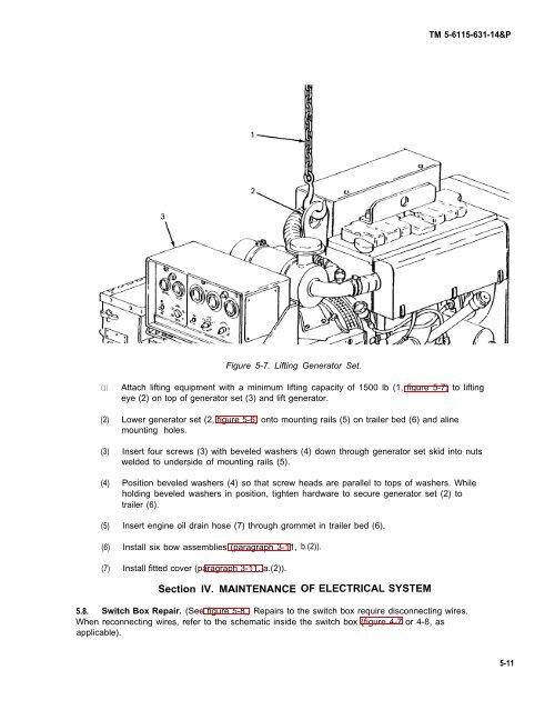
TM 5-<strong>6115</strong>-631-14&PFigure 5-7. Lifting Generator Set.(1)(2)(3)(4)(5)Attach lifting equipment with a minimum lifting capacity of 15<strong>00</strong> lb (1, figure 5-7) to liftingeye (2) on top of generator set (3) and lift generator.Lower generator set (2, figure 5-6) onto mounting rails (5) on trailer bed (6) and alinemounting holes.Insert four screws (3) with beveled washers (4) down through generator set skid into nutswelded to underside of mounting rails (5).Position beveled washers (4) so that screw heads are parallel to tops of washers. Whileholding beveled washers in position, tighten hardware to secure generator set (2) totrailer (6).Insert engine oil drain hose (7) through grommet in trailer bed (6).(6)(7)Install six bow assemblies (paragraph 3-11,Install fitted cover (paragraph 3-11, a.(2)).Section IV. MAINTENANCEb.(2)).OF ELECTRICAL SYSTEM5.8. Switch Box Repair. (See figure 5-8,) Repairs to the switch box require disconnecting wires.When reconnecting wires, refer to the schematic inside the switch box (figure 4-7 or 4-8, asapplicable).5-11


