RMXS48LVJU - Daikin AC
RMXS48LVJU - Daikin AC
RMXS48LVJU - Daikin AC

You also want an ePaper? Increase the reach of your titles
YUMPU automatically turns print PDFs into web optimized ePapers that Google loves.
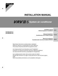
2. In case of installing multiple units (2 units or more) in lateral connectionper row• In case obstacles exist in front of the air inlet and on both sidesof the unit (Refer to figure 4-[3])When something is obstructing the top1. Installation of single unit• In case obstacles exist only in front of the air inlet(Refer to figure 5-[1])• In case obstacles exist in front of the air inlet and on both sidesof the unit (Refer to figure 5-[2])2. In case of installing multiple units (2 units or more) in lateral connectionper row• In case obstacles exist in front of the air inlet and on both sidesof the unit (Refer to figure 5-[3])(7)-2 IN CASE OBST<strong>AC</strong>LES EXIST IN FRONT OF THE OUTLETSIDEWhen nothing is obstructing the top1. Installation of single unit (Refer to figure 6-[1])2. In case of installing multiple units (2 units or more) in lateral connectionper row (Refer to figure 6-[2])When something is obstructing the top1. Installation of single unit (Refer to figure 6-[3])2. In case of installing multiple units (2 units or more) in lateral connectionper row (Refer to figure 6-[4])(7)-3 IN CASE OBST<strong>AC</strong>LES EXIST IN FRONT OF BOTH THEAIR INLET AND OUTLET SIDESPattern 1: Where obstacle in front of the air outlet is higher than theunit.(There is no height limit for obstructions on the intake side.)When nothing is obstructing the top1. Installation of single unit (Refer to figure 7-[1])2. In case of installing multiple units (2 units or more) in lateral connectionper row (Refer to figure 7-[2])When something is obstructing the top1. Installation of single unit (Refer to figure 7-[3])Relation of dimensions of H, A, and L are shown in the table below.inch (mm)LA0 < L ≤ 1/2H 30 (750)0L ≤ H1/2H < L ≤ H 40 (1000)H < LSet the frame to be L ≤ HNoteGet the lower part of the frame sealed so that air from the outletdoes not bypass.2. Series installation (up to 2 units) (Refer to figure 7-[4])Relation of dimensions of H, A, and L are shown in the tablebelow.inch (mm)LA0 < L ≤ 1/2H 40 (1000)L ≤ H1/2H < L ≤ H 50 (1250)H < LSet the frame to be L ≤ HNote1. Get the lower part of the frame sealed so that air from the outletdoes not bypass.2. Only two units at most can be installed in series.Pattern 2: Where obstacles in front of the air outlet is lower than theunit.(There is no height limit for obstructions on the intakeside.)When nothing is obstructing the top1. Installation of single unit (Refer to figure 7-[5])2. In case of installing multiple units (2 units or more) in lateral connectionper row (Refer to figure 7-[6])Relation of dimensions of H, A, and L are shown in the tablebelow.inch (mm)LA0 < L ≤ 1/2H 10 (250)1/2H < L ≤ H 12 (300)When something is obstructing the top1. Installation of single unit (Refer to figure 7-[7])Relation of dimensions of H, A, and L are shown in the tablebelow.inch (mm)LA0 < L ≤ 1/2H 4 (100)L ≤ H1/2H < L ≤ H 8 (200)H < LSet the frame to be L ≤ HNoteGet the lower part of the frame sealed so that air from the outletdoes not bypass.2. Series installation (up to 2 units) (Refer to figure 7-[8])Relation of dimensions of H, A, and L are shown in the tablebelow.inch (mm)LA0 < L ≤ 1/2H 10 (250)L ≤ H1/2H < L ≤ H 12 (300)H < LSet the frame to be L ≤ HNote1. Get the lower part of the frame sealed so that air from the outletdoes not bypass.2. Only 2 units at most can be installed in series.(7)-4 IN CASE OF ST<strong>AC</strong>KED INSTALLATION1. In case obstacles exist in front of the outlet side(Refer to figure 8-[1])Note1. No more than 2 units should be stacked.2. About 4 inch (100 mm) is required as the dimension for layingthe upper outdoor unit’s drain pipe.3. Shut off the Z part (the area between the upper outdoor unitand the lower outdoor unit) so that outlet air does not bypass.2. In case obstacles exist in front of the air inlet (Refer to figure 8-[2])Note1. No more than 2 units should be stacked.2. About 4 inch (100 mm) is required as the dimension for layingthe upper outdoor unit’s drain pipe.3. Shut off the Z part (the area between the upper outdoor unitand the lower outdoor unit) so that outlet air does not bypass.(7)-5 IN CASE OF MULTIPLE-ROW INSTALLATION (FOR ROOFTOP USE, ETC.)1. In case of installing 1 unit per row (Refer to figure 9-[1])2. In case of installing multiple units (2 units or more) in lateral connectionper row (Refer to figure 9-[2])Relation of dimensions of H, A, and L are shown in the tablebelow.inch (mm)L ≤ HH < LLA0 < L ≤ 1/2H 10 (250)1/2H < L ≤ H 12 (300)Installation impossible.5 English
5. PRECAUTIONS ON INSTALLATION• Install making sure the unit is level and the foundation is sturdyenough to prevent vibration noise.• In accordance with the foundation drawing in figure 10, fix the unitsecurely by means of the foundation bolts.(Prepare 4 sets of M12 foundation bolts, nuts and washers eachwhich are available on the market.)• The foundation bolts should be inserted 15/16 inch (20 mm).(Refer to figure 10)1. Diagram of lower surface• Locations where drainage from the outdoor unit might be a problem.In such locations, for example, where the drainage might drip ontopassersby, lay the drain piping using the separately sold drainplug.• When laying the drain, at least 4 inch (100 mm) from the bottom ofthe outdoor unit is needed.• Make sure the drain works properly.(Watch out for water leaks if piping is brought out the bottom.)(Refer to figure 11)1. Drain plug2. 4 tabs3. Drain receiver4. Insert the drain receiver as far as possible into the drainplug and hook the tabs.5. Bottom frame drain hole6. (1) Insert the drain plug through the drain hole in thebottom frame shown in figure 12.(2) Turn the drain plug along the guides until it stops(approx. 90°), and then attach the bottom frame.7. Guide(Refer to figure 12)1. Air outlet side2. Diagram of lower surface3. Drain hole[How to remove the transport clasp]• A yellow transport clasp and washer are attached to the legs ofthe compressor to protect the unit during transportation, soremove them as shown in figure 13.(Refer to figure 13)1. Compressor2. Securing nut3. Washer4. Transport clasp5. Turn in the direction of the arrow and remove.6. Sound-proof cover7. Do not remove with the cover open.(1) Open the sound-proof cover as shown in figure 13.Do not pull the sound-proof cover or remove it from the compressor.(2) Remove the securing nut.(3) Remove the washer.(4) Remove the transport clasp as shown in figure 13.(5) Retighten the securing nut.(6) Return the sound-proof cover as it was.6. FIELD WIRINGCAUTIONTo the electrician• Do not operate until refrigerant piping work is completed.(If operated before complete the piping work, the compressormay be broken down.)• Be sure to install a ground fault circuit interrupter.(This unit uses an inverter, so install the ground fault circuit interrupterthat be capable of handling high harmonics in order toprevent malfunctioning of the ground fault circuit interrupteritself.)6-1 Wiring connection example for whole system• Electrical wiring work should be done by a certified professional.• Follow the “Electrical wiring diagram face plate” when carrying outany electrical wiring.Only proceed with wiring work after blocking off all power.• Make sure the ground resistance is no greater than 4Ω .• Attach a ground-fault circuit interrupter.• Ground the indoor and outdoor units.• Do not connect the ground wire to gas pipes, sewage pipes, lightningrods, or telephone ground wires.• Gas pipes: can explode or catch fire if there is a gas leak.• Sewage pipes: no grounding effect is possible if hard plasticpiping is used.• Telephone ground wires and lightning rods: dangerouswhen struck by lightning due to abnormal rise in electrical potentialin the grounding.• Use copper wire.• When doing the electrical wiring, always shut off the power sourcebefore working, and do not turn on the switch until all work is complete.• This unit has an inverter, so it must be grounded in order to reducenoise and prevent it affecting other appliances, and also torelease any electrical build-up in the unit case due to leaked current.• Do not install a power-factor improving phase-advancing capacitorunder any circumstances.(Not only will this not improve the power factor, but it might causea fire.)• Connect the wire securely using designated wire and fix it withattached clamp without applying external pressure on the terminalparts (terminal for power wiring, terminal for transmission wiringand ground terminal). See “6-3 How to connect the powersupply wiring”.• Left-over wiring should not be wrapped and stuffed into the unit.• To prevent the power wiring from being damaged by the knockhole edges, put it in a wiring pipe or plastic tube to protect it.• Secure the wiring with the included clamp so that it does not comein contact with the piping or stop valve.(See “6-3 How to connect the power supply wiring”.)CAUTION• Use a power wire pipe for the power supply wiring.• Outside the unit, make sure the weak electric wiring (i.e. for theremote controller cord, between units, etc.) and the strong electricwiring do not pass near each other, keeping them at least2 inch (50 mm) apart.Proximity may cause electrical interference, malfunctions, andbreakage.• Be sure to connect the power wiring to the power wiring terminalblock and secure it as described in “6-3 How to connect thepower supply wiring”.• Inter-unit wiring should be secured as described in “6-4 Interunitwiring connection procedure”.• Secure wiring with binding band (accessory) to avoid contactwith piping.• Make sure the wiring and the front panel do not stick up abovethe structure, and close the cover firmly.(Refer to figure 14)1. The power source is supplied to each BP unitindividually.2. Branch switch and over-current interrupter (ground-faultcircuit interrupter)3. Power supply4. Outdoor unit5. 16V6. 208/230V7. Indoor unit8. BP unit9. Ground wireEnglish 6
6-2 How to lay the power supply wiring and transmissionwiringLet the power supply wiring and transmission wiring with a conduitpass through one of the knockout holes on the front or side cover,and let the transmission wiring with a conduit pass through anotherknockout hole.• For protection from uninsulated live parts, thread the power supplywiring and the transmission wiring through the included insulationtube and secure it with the included binding band.Insulation tube(accessory)Ground wireInsulation tube(accessory)Binding band(accessory)2 inch(50 mm)or moreBinding band(accessory)Power supplywiring5/8 inch 5/8 inch(15 mm) (15 mm)3 inch(76mm)Transmissionwiring3 inch (76mm)Precautions when knocking out knock holes• Open the knock holes with a hammer or the like.• After knocking out the holes, we recommend you remove burrs inthe knock holes and paint the edges and areas around the edgesusing the repair paint to prevent rusting.• When passing wiring through knock holes, make sure there areno burrs, and protect the wiring with protective tape.BurrIf small animals might enter theunit, block the knock holes with anappropriate material (field supply).(Refer to figure 15)1. Screw2. Unfasten the screw and open the cover.(Refer to figure 16)1. Stop valve attachment plate2. Power supply wiring (including ground wire) or transmissionwiring.3. Backward4. Knockout hole5. Sideways6. Forward7. Electrical Component Box8. Terminal block (X2M)9. Binding band (accessory)10. Connecting power supply wiring11. Ground wire (yellow/green)12. Terminal block (X1M)13. Transmission wiring14. (To X2M [To BP unit] (F1, F2))15. Insulation tube (large) (accessory)16. Insulation tube (small) (accessory)17. Cut off the insulation tube sticking out of the outdoor unit.• Wiring of different thicknesses cannot be connected to the powerterminal block.(Slack in the power wiring may cause abnormal heat.)• Use sleeve-insulated round pressure terminals for connections tothe power terminal block. When none are available, connect wireof the same diameter to both sides, as shown in the figure.Insulating sleeveRound crimp-styleterminalConnect wiresof the same gaugeto both side.Follow the instructions below if the wiring gets very hot due toslack in the power wiring.• For wiring, use the designated power wire and connect firmly,then secure using the included clamping material to prevent outsidepressure being exerted on the terminal block.• Use an appropriate screwdriver for tightening the terminal screws.A screwdriver with a small head will strip the head and makeproper tightening impossible.• Over-tightening the terminal screw may break it.See the table below the tightening torque of the terminal screws.Tightening torque1.76-2.15 ft·lbfM5 Power terminal(2.39-2.91 N·m)0.87-1.06 ft·lbfM4 Shield ground(1.18-1.44 N·m)0.58-0.72 ft·lbfM3 Transmission wiring terminal block(0.8-0.97 N·m)6-3 How to connect the power supply wiringCAUTIONAttach a ground-fault circuit interrupter.• A ground-fault circuit interrupter is required in order to preventelectric shock and fires.Model name Frequency VoltageCAUTIONDo not connectwires of the samegauge to one side.Electric WireDo not connectwires of differentgauges.Good Wrong WrongRatedcurrentfor fusesMaximumoutdoor unitoperatingcurrent<strong>RMXS48LVJU</strong> 60Hz 208/230V 30A 27A• The wiring should be selected in compliance with local specifications.See the table above.• Always turn off the power before doing wiring work.• Grounding should be done in compliance with local laws andregulations.• Attach a ground-fault circuit interrupter.(This unit has an inverter, so an interrupter capable of handlinghigh frequencies is needed to prevent malfunction of the interrupteritself.)• As shown in figure 16, when connecting the power supply wiringto the power supply terminal block, be sure to clamp securely.• Once wiring work is completed, check to make sure there are noloose connections among the electrical parts in the control box.7 English
6-4 Inter-unit wiring connection procedure• Between indoor units in the same system, pass the wiringbetween the units as shown in figure 17. (There is no polarity.)(Refer to figure 17)1. Terminal block (X2M)2. Use balance type shield wire (with no polarity).3. BP unit4. Not used for this model. Never connect wires, or theentire system will be damaged.Precautions regarding the length of wiring between unitsExceeding the following limits may cause transmission malfunctions,so observe them.Max. wiring length Max. 656 ft (200 m)Total wiring length Max. 984 ft (300 m)Precautions regarding wiring between units• Do not connect 208/230V power wiring to terminals for theinter-unit wiring. Doing so would destroy the entire system.• Wiring to the BP unit should be wired to F1 and F2 (To BP unit) onthe outdoor unit’s terminal block (X2M).Note• The above wiring should be wired using AWG 18-16 (0.75 – 1.25mm 2 ) shielded (balance type) wiring.(See figure 16 for how to ground the shielded parts.)• All inter-unit wiring is to be procured on site.CAUTION(Refer to figure 18)1. Branch2. Caution on branches in the wiring among BP units3. The following branches can not be performed7. PRECAUTIONS ON REFRIGERANTPIPINGCAUTIONTo the pipe-layer• Do not operate the unit with the transport clasp attached. Thiscan cause abnormal shaking or noise. See “5. PRECAUTIONSON INSTALLATION” and “How to remove the transport clasp”.7-1 Installation toolsUse the right parts to ensure tolerance and to prevent foreign matterfor entering.Gauge manifold, charge hose, etc.• Make sure to use installation tools that are exclusively used forR410A installations to withstand the pressure and to prevent foreignmaterials (e.g. mineral oils such as SUNISO and moisture)from mixing into the system.(The screw specifications differ for R410A.)Vacuum pump• Use extreme caution to prevent pump oil from flowing backwardsthrough the system when the pump is stopped.• Use a vacuum pump which can evacuate to –14.6 PSI (–100.7kPa (5Torr, –755mmHg)).7-2 Selecting piping material• Use pipes that have no contaminants adhered to their inner surfaces(such as sulfur, iron oxide, dust, cutting chips, oil and moisture). (It isdesirable that adhered oil inside the piping is 0.00006 lb. (30 mg) orless per 32.8 ft (10 m).)• The wall thickness of the refrigerant piping should comply with locallaws and regulations. The design pressure for R410A is 478 PSI(3.3 MPa).• Use the following material for the refrigerant piping.Material: Jointless phosphor-deoxidized copper pipe.• Thickness and size: choose based on the piping size selectionmethod on the “7-8 Air tight test and vacuum drying”.• Make sure to use the separately sold refrigerant branch kit whenbranching the piping.• Piping work should be done within the maximum length, heightdifference, and length after branches set out in “7-8 Air tight testand vacuum drying”.• Install the refrigerant branch kit while observing the following conditionand referring to the installation manual offered as an accessoryof the kit.(Refer to figure 19)1. Install the REFNET joint so it splits horizontally or vertically.2. Horizontal surface3. A-arrow view4. ±30° or less5. Level6. Vertical is also OK7-3 Protection against contamination wheninstalling pipes• Wrap the piping to prevent moisture, dirt, dust, etc. from enteringthe piping.• Exercise caution when passing copper piping through thethrough-holes and when passing them out to the outside.Place Installation period Protection methodMore than a month Pinch the pipeOutdoorLess than a monthPinch or tape the pipeIndoorRegardless of the period7-4 Pipe connection• See “Stop valve operation procedure” in “7-8 Air tight test andvacuum drying” regarding handling of the stop valve.• Only use the flare nuts included with the unit. Using different flarenuts may cause the refrigerant to leak.• Be sure to perform a nitrogen blow when brazing.(Brazing without performing nitrogen replacement or releasingnitrogen into the piping will create large quantities of oxidized filmon the inside of the pipes, adversely affecting valves and compressorsin the refrigerating system and preventing normal operation.)NoteThe nitrogen used when brazing while flowing the nitrogen should beset to 2.9 PSI (0.02 MPa) (2.8 PSI / 0.019 MPa: just enough to feel abreeze on your cheek) with the decompression valve.• Do not mix any refrigerant other than that specified into the refrigerantsystem.• Do not mix air into the refrigerant system.CAUTIONDo not use a flux when brazing the refrigerant pipe joints.Use phosphor copper brazing (BCuP-2/B-Cu93P-710/795) whichdoes not require flux.(Using a chlorine flux may cause the pipes to corrode, and if itcontains fluoride it may cause the refrigerant lubricant to deteriorate,adversely affecting the refrigerant piping system.)(Refer to figure 20)1. Refrigerant pipe2. Location to be brazed3. Regulator4. Nitrogen5. Manual valve6. Taping7-5 Connecting the refrigerant piping• The local inter-unit piping is connectable in four directions.(Refer to figure 21)1. Front panel2. Pipe outlet panel3. Backward4. Sideways5. Downward6. Pipe outlet panel screw7. Forward8. Screw for front panelEnglish 8
• When connecting the pipings downward, remove the knockoutby making 4 holes in the middle on the each side of theknockout with a drill.(Refer to figure 22)1. Dril2. Center area around knockout hole3. Knockout hole4. Slit• After knocking out the knock-out, it is recommended to applyrepair paint to the edge and the surrounding end surfaces to preventrusting.(Refer to figure 23)1. Bottom frame2. Inter-unit pipingNoteCutting out the 2 slits makes it possible to install as shown in figure23. (Use a metal saw to cut out the slits.)• Please refer to the Table 1 for the dimensions for processingflares.• When connecting the flare nut, coat the inner surface of the flarewith refrigeration oil and initially tighten by hand 3 or 4 turnsbefore tightening firmly.• Please refer to the Table 1 for the tightening torque. (Too muchtightening will end up in splitting of the flare.)Table 1Pipe sizeφ 3/8 inch(φ 9.5mm)φ 5/8 inch(φ 15.9mm)φ 3/4 inch(φ 19.1mm)Tighteningtorque24.1-29.4 ft·lbf(32.7-39.9N·m)45.6-55.6 ft·lbf(61.8-75.4N·m)71.7-87.5 ft·lbf(97.2-118.6N·m)A dimensionsforprocessingflares0.504-0.520 inch(12.8-13.2mm)0.760-0.776 inch(19.3-19.7mm)0.929-0.944 inch(23.6-24.0mm)Flare shape• If a torque wrench is not available, there is a place where the tighteningtorque will suddenly increase if a normal wrench is used totighten the flare nut.From that position, further tighten the flare nut the angle shownbelow.Recommended arm lengthPipe size Further tightening angleof toolφ 3/8 inch(φ 9.5mm)φ 5/8 inch(φ15.9mm)φ 3/4 inch(φ 19.1mm)60°- 90 °30°- 60°20° - 35°Refrigeration oilApprox. 7-7/8 inch(200 mm)Approx. 11-13/16 inch(300 mm)Approx. 17-11/16 inch(450 mm)• After all the piping has been connected, use nitrogen to perform agas leak check.(Refer to figure 24-[1])1. Front connection2. Gas side accessory pipe (1)3. Gas side accessory pipe (3)4. Gas side piping (field supply)5. Cut at an appropriate length.6. Gas side accessory pipe (2)90˚± 2˚45˚± 2˚AR0.016-0.031 inch(R0.4-0.8mm)(Refer to figure 24-[2])1. Rear-side connection2. Gas side accessory pipe (1)3. Gas side accessory pipe (2)4. Gas side accessory pipe (3)5. Gas side piping (field supply)(Refer to figure 24-[3])1. Side connection2. Gas side accessory pipe (2)3. Cut at an appropriate length.4. Gas side piping (field supply)5. Gas side accessory pipe (3)6. Gas side accessory pipe (1)(Refer to figure 24-[4])1. Bottom connection2. Cut at an appropriate length.3. Gas side piping (field supply)4. Gas side accessory pipe (3)5. Gas side accessory pipe (1)Precautions for connecting pipes• Be careful not to let the inter-unit piping come into contact with thecompressor terminal cover.Adjust the height of the insulation material on liquid pipe when ithas the possibility of getting in contact with the terminal. Alsomake sure that the inter-unit piping does not touch the mountingbolt of the compressor.(Refer to figure 26)1. Terminal cover2. Compressor3. Corking, etc.4. Insulation material5. Bolts6. Inter-unit piping• If installing the outdoor unit higher than the indoor unit, caulk thespace around insulation and tubes because condensation on thecheck valve can seep through to the indoor unit side.[Preventing foreign objects from entering]• Plug the pipe through-holes with putty or insulating material (procured locally) to stop up all gaps, as shown in figure 25.(Insects or small animals entering the outdoor unit may cause ashort in the control box.)(Refer to figure 25)1. Putty or insulating material2. (field supply)7-6 Heat insulation of piping• If you think the humidity inside the ceiling might exceed 86°F(30°C) and RH80%, reinforce the insulation on the cooling piping.(At least 0.78 inch (20 mm) thick) (Condensation may form on thesurface of the insulation.)• Be sure to insulate the inter-unit piping (liquid and gas-side) andthe refrigerant branch kit. (Not insulating them may cause leaking.)(The highest temperature that the gas-side piping can reach isaround 248°F (120°C), so be sure to use insulating material which isvery resistant.)CAUTIONFor local insulation, be sure to insulate all the way to the pipe connectionsinside the machine.Exposed piping may cause leaking or burns on contact.9 English
7-7 Example of connectionExample of connection(Connection of 7 units heat pump system)1 indoor unitBP 1 BP unitArefrigerant branch kit (refnet joint)MaximumallowablelengthBetween outdoor and BP unitsBetween BP and indoor unitsTotal piping lengthTotal piping lengthBetween BP and indoor unit1 room lengthAllowableheightBetween outdoor and indoor unitsBetween outdoor and BP unitsBetween BP and BP unitsBetween indoor and indoor unitsMinimum allowable length∗1 Since the sound of refrigerant may be transferred fromthe outdoor unit to the indoor unit, make the pipe lengthfrom the outdoor unit to the first junction 16.4 ft (5 m) or longer.Difference in heightDifference in heightDifference in heightDifference in heightPiping lengthAllowable length after the branch∗2 Branch kit are recommanded to set as possibleas near the BP units.c, d, e are recommanded to be as possible as short.Piping lengthRefrigerant branch kit selection refrigerant branch kits can only be used with R410APipe size selectionHow to calculate the additional refrigerant to be chargedAdditional refrigerant to be charged R (lb. /kg)R should be rounded off in units of 0.1 lb. (0.1kg).Branch with refnet jointab cH2deH1BPf gH3BP 2BP 3i j k4 5 6 71 2hH43Pipe length between outdoor and BP units ≤ 180 ft (55m)[Example] a+b+c+d+e ≤ 180 ft (55m)Piping length between BP and indoor units: 262ft (80m)[Example] f+g+h+i+j+k+ ≤ 262ft (80m)Piping length between BP and indoor unit ≤ 49 ft (15m)[Example] f, g, h, i, j, k, ≤ 49 ft (15m)Difference in height between outdoor and indoor units (H1) ≤ 98 ft (30m)Difference in height between outdoor and BP units (H2) ≤ 98 ft (30m)Difference in height between BP and BP units (H3) ≤ 49 ft (15m)Difference in height between indoor and indoor units (H4) ≤ 49 ft (15m)Pipe length between outdoor unit and first refrigerant branch kit (refnet joint) ≥ 16.4 ft (5m)[Example] a ≥ 16.4 ft (5m)Piping length from first refrigerant branch kit (refnet joint) to indoor unit ≤ 131 ft (40m)[Example] unit 6: b+c+k ≤ 131 ft (40m)[Example] unit 5: b+e+j ≤ 131 ft (40m)[Example] unit 3: d+h ≤ 131 ft (40m)Refrigerant branch kit (refnet joint) name : KHRP26M22T• Piping size (Outer diameter × minimum thickness)symbol Gas pipe Liquid pipeBetween outdoor unit and first refrigerant branch kit a φ 3/4 × 0.039 (φ 19.1 × 1.0) φ 3/8 × 0.031 (φ 9.5 × 0.8)Between refrigerant branch kit and refrigerant branch kit b φ 5/8 × 0.031 (φ 15.9 × 1.0) φ 3/8 × 0.031 (φ 9.5 × 0.8)unit : inch (mm)Between refrigerant branch kit and BP unitc, d, e See the table ATable ATotal indoor capacity Q Gas pipeLiquid pipe[Example]Qc, Qd, Qe ≤ 17000 Btu (5.0 kW)Qc, Qd, Qe > 17000 Btu (5.0 kW) φ 1/2 × 0.031 (φ 12.7 × 0.8) φ 5/8 × 0.039 (φ 15.9 × 1.0) φ 1/4 × 0.031 (φ 6.4 × 0.8)φ 3/8 × 0.031 (φ 9.5 × 0.8)indoor 1: 9000 Btu/hindoor 2: 12000 Btu/h Qd = 39000 Btu/hindoor 3: 18000 Btu/h∗Qc, Qd, Qe is total connected indoor capacity=> (Gas pipe) φ5/8 × 0.031 (φ15.9 × 1.0) / (Liquid pipe) φ3/8 × 0.031 (φ9.5 × 0.8)∗c, d, e indicates the symbols in the figure⎛ ⎞ [Example] for refrigerant branch using refnet jointTotal length (ft / m) Total length (ft / m) R= of liquid piping size at ⎟⎟⎠ 0.036 lb./ft×(0.054 kg/m)+ of liquid piping size at ⎟⎟⎠ 0.015 lb./ft(0.022 kg/m)φ3/8 inch (φ9.5 mm)φ1/4 inch (φ6.4 mm)a: φ 3/8 × 32 (φ 9.5 × 10)b: φ 3/8 × 32 (φ 9.5 × 10)c: φ 1/4 × 32 (φ 6.4 × 10)0.036(0.054)d: φ 3/8 × 32 (φ 9.5 × 10)e: φ 3/8 × 32 (φ 9.5 × 10)f : φ 1/4 × 32 (φ 6.4 × 10)0.015(0.022)g: φ 1/4 × 32 (φ 6.4 × 10)h: φ 1/4 × 32 (φ 6.4 × 10)i : φ 1/4 × 32 (φ 6.4 × 10)0.036(0.054)0.015(0.022)R=[(a+b+d+e)× ]+[(c+f+g+h+i+j+k+ )× ]=[ × ]+[ × ]=128(40)234(73)unit : inch× ft (mm× m)j : φ 1/4 × 32 (φ 6.4 × 10)k: φ 1/4 × 16 (φ 6.4 × 5): φ 1/4 × 26 (φ 6.4 × 8)8.118 → 8.1 lb.(3.766 → 3.8kg)A1BEnglish 10
7-8 Air tight test and vacuum dryingAfter doing the piping, perform the following inspections.Air tight testBe sure to use nitrogen gas. (See the figure (“Stop valve operationprocedure”) for the location of the service port.)[Procedure]Pressurize from the liquid pipes and gas pipes to 478 PSI (3.3 MPa)(and not above 478 PSI (3.3 MPa)). If there is not pressure drop overthe next 24 hours, the equipment has passed the test.If the pressure drops, check for leakage positions. (Confirm that thereis no leakage, then release nitrogen.)Vacuum dryingUse a vacuum pump that can create a vacuum down to at least–14.6 PSI (–100.7 kPa).[Procedure]Operate the vacuum pump for at least 2 hours from both the liquidand gas pipes and decrease the pressure to at least –14.6 PSI(–100.7 kPa).Leave at below –14.6 PSI (–100.7 kPa) for at least 1 hour and makesure that the vacuum gauge does not rise. (If it does rise, there iseither still moisture in the system or a leak.)Cases where moisture might enter the piping (i.e., if doing workduring the rainy season, if the actual work takes long enough thatcondensation may form on the inside of the pipes, if rain might enterthe pipes during work, etc.)After performing the vacuum drying for 2 hours, pressurize to7.2 PSI (0.05 MPa) (i.e., vacuum breakdown) with nitrogen gas, thendepressurize down to at least –14.6 PSI (–100.7 kPa) for an hourusing the vacuum pump (vacuum drying). (If the pressure does notreach at least –14.6 PSI (–100.7 kPa) even after depressurizing for atleast 2 hours, repeat the vacuum breakdown - vacuum drying process.)Leave as a vacuum for 1 hour after that, and make sure thevacuum gauge does not rise.(Refer to figure 27)1. Nitrogen2. Decompression valve3. Vacuum pump4. Valve (open)5. Charge hose6. Stop valve service port7. Indoor unit8. Gas line stop valve (close)9. Liquid line stop valve (close)10. Indicates local procurement11. Outdoor unit12. BP unitNoteThe stop valve must always be turned to “closed”.Otherwise the refrigerant in the outdoor unit will pour out.Stop valve operation procedurePrecautions when handling the stop valve• The names of parts needed to operate the stop valve are shownin the figure below. The unit is shipped from the factory with thestop valve turned to the “closed” position.Servicing port• Since the side boards may be deformed if only a torque wrench isused when loosening or tightening flare nuts, always lock the stopvalve with a wrench and then use a torque wrench.• In cases where the unit is run in heating mode when the outsidetemperature is low or in other situations where the operating pressuremight drop, seal the gas-side flare nut on the stop valve withsilicon sealant or the like to prevent it from freezing.Silicon sealing pad(Make sure that there is no gap)Stop valve operation procedureHave a hexagonal wrench ready (size: 0.2 inch and 0.3 inch / 4 mmand 6 mm).Opening the valve1. Place the hexagonal wrench on the valve bar and turn counterclockwise.2. Stop when the valve bar no longer turns. It is now open.Close the valve1. Place the hexagonal wrench on the valve bar and turn clockwise.2. Stop when the valve bar no longer turns. It is now closed.Direction to openPrecautions for handling valve lid• A seal is attached to the point indicated by the arrow.Take care not to damage it.Valve lid• Be sure to tighten the valve lid securely after operating the valves.Liquid-side tightening torque Gas-side tightening torque10.0-12.2 ft·lbf(13.5-16.5 N·m)Precautions for handling servicing portDirection to openStop valve(lid attachment)16.6-20.3 ft·lbf(22.5-27.5 N·m)• Use a push-rod-provided charging hose for operation.• Be sure to tighten the valve lid securely after operation.Tightening torque .......... 8.5-10.3 ft·lbf (11.5-14.0 N·m)Valve barValve lidInter-unit piping connection11 English
Location of “Cautions on Service” plate.The back of front panelFront panel8. ADDITIONAL REFRIGERANT CHARGEWARNING• When leaving the unit with the power on, be sure toswitch with another person doing the installation orclose the front panel.8-1 Before adding refrigerant• Make sure the following work and inspection is complete, inaccordance with the installation manual.•Piping• Wiring• Airtightness test, Vacuum drying8-2 Checking the refrigerant tank• Check whether the tank has a siphon pipe before charging andplace the tank so that the refrigerant is charged in liquid form.(See the figure below.)Tank with siphon pipeThere is a siphonpipe inside, so thecylinder need not beupside-down to fillwith liquid.(Stand the cylinderupright when filling.)8-3 Adding refrigerantFilling after calculating the amount of refrigerant to add1. Calculate the amount of refrigerant to add as described in “Calculatingthe amount of refrigerant to add” in “7-7 Example of connection(page 10)”.2. After the vacuum drying is finished, open valve A and charge thecalculated amount of refrigerant through the service port for theliquid-side stop valve.3. Close valve A after charging is complete.Note:If all the refrigerant to be added cannot be charged using theabove procedure, right-hand the procedure below and rechargethe refrigerant.Status of the stop valve and other valves when adding refrigerant• See “Stop valve operation procedure” in “7-8 Air tight test andvacuum drying (page 11)” for details on how to use the stop valve.(Refer to figure 28)1. R410A Tank (Siphon system) 5. Stop valve service port2. Measuring instrument 6. Gas line stop valve3. Valve A 7.Outdoor unit4. BP unit 8.Liquid line stop valveState of valve A and the stopvalveBefore starting to charge therefrigerantDuring charging of the refrigerantValve AOther tanksStand the tankupside down andcharge.Liquid linestop valveGas linestop valveClose Close CloseOpen Close CloseIf all the refrigerant could not be addedAdd refrigerant using the following procedure. See the “Cautions onService” plate on the back of the front panel for details on the settingsfor adding refrigerant.[Procedure]1. Close the front panel and turn on the power to all outdoor unitsand indoor units in the refrigeration system.2. Open the gas and liquid-side stop valve all the way and add therefrigerant. (Open valve A immediately after starting the compressor.)3. Once the appropriate amount of refrigerant is in, press the confirmationbutton (BS3) on the outdoor unit PC board (A2P), and stopoperation after adding the refrigerant.4. Close valve A after charging is complete.Status of the stop valve and other valves when adding refrigerantoperation• See “Stop valve operation procedure” in “7-8 Air tight test andvacuum drying (page 11)” for details on how to use the stopvalve.• Connect the service port (for charging refrigerant) inside theunit. When the unit is shipped from the factory, refrigerant isalready charged, so be careful when connecting the chargehose.• After adding the refrigerant, do not forget to close the lid of theservice port (for adding refrigerant). The tightening torque of thelid is 8.5-10.3 ft·lbf (11.5-14.0 N·m)(Refer to figure 29)1. Gas line stop valve 2. Liquid line stop valve3. Stop valve service port 4. BP unit5. Measuring instrument 6. R410A Tank (Siphonsystem)7. Valve A 8. Service port9.(For adding refrigerant) 10.Outdoor unitState of valve A and the stopvalveBefore starting to charge therefrigerantDuring charging of the refrigerant9. POST-WORK CHECKSPerform the following checks after work is complete.(1) Drain pipe connection, removal of transport clasp →See “5. PRECAUTIONS ON INSTALLATION (page 6)”.(2) Incorrect power supply wiring, loose screws →See “6-3 How to connect the power supply wiring (page 7)”.(3) Incorrect inter-unit wiring, loose screws →See “6-4 Inter-unit wiring connection procedure (page 8)”.(4) Incorrect refrigerant piping connections →See “7. PRECAUTIONS ON REFRIGERANT PIPING (page 8)”.(5) Piping sizes, use of insulation →See : “7-2 Selecting piping material (page 8)”.“7-6 Heat insulation of piping (page 9)”.(6) Stop valve check →Make sure both the liquid-side and gas-side stop valves areopen.(7) Record of Amount of Refrigerant Added →Record it on “Recording the additionally charged refrigerantquantity” on the “Cautions on Service” plate.(8) Measuring the insulation of the main power circuit →• Use a 500V mega-tester.• Do not use the mega-tester for weak currents other than 208/230V. (Inter-unit wiring)CAUTIONValve ALiquid linestop valveGas linestop valveClose Open OpenOpen Open OpenTo the pipe-layerAfter completing installation, be sure to open the valve.(Operating the unit with the valve shut will break the compressor.)English 12
10. TEST RUNThis unit is equipped with a crank case heater to ensure smoothstartup. Be sure to turn the power on at least 6 hours beforeoperation in order to have power running to the crank caseheater.WARNINGWhen leaving the unit with the power on, be sure toswitch with another person doing the installation orclose the front panel.Precautions before turning the power on• Using insulating sheets, tape electric parts as described in the“Cautions on Service” plate on the back of the front panel.• All indoor units connected to the outdoor unit operate automatically.Complete work on the indoor units in order to ensure maximumsafety.10-1 Power On–Check Operation• Make sure to perform the check operation after installation.(If the air conditioner is operated using the indoor remote controllerwithout performing the check operation, the malfunction code“U3” is displayed in the indoor remote controller, and normal operationis disabled.)• When making settings on the outdoor unit PC board (A2P) afterturning the power on, do not touch anything other than the pushbuttonswitches and dip switches.(See the “Cautions on Service” plate for the locations of thepush-button switches (BS1-5) and dip switches (D1-1, 2) on thePC board (A2P).)• During the operation, monitor the outdoor unit operation statusand check for any incorrect wiring.1. Close the outdoor unit’s front panel.Turn the power on for the outdoorunit and the BP unit.2. • Open the outdoor unit’s front panel.• Make sure the LED display on the outdoor unit’s PC boards (A1P andA2P) are as shown in the following chart.A1PA2PLED display(Default statusbefore delivery)SEVICEMONITORHAPMODETEST/HWLBe sure to turn the power on at least6 hours before operation in order to havepower running to the crank case heater.IND MASTER SLAVE L.N.O.P DEMANDH1P H2P H3P H4P H5P H6P H7PLED display: OFF ON BlinkingTo avoid the risk of electric shock, do not touch anything other than thepush-button switches on the PC board (A2P) when making settings.3. • When the customer requestsquiet operation or demandoperation, make these settingsusing the push-button switches(BS1-5) on the outdoor unit’sPC board (A2P).• Operate the push-buttonswitches through the openingafter protecting it with aninsulation cover.(See the “Cautions on Service”plate for details.)4. • Check that the liquid and gas-sidestop valves are open, and ifthey are closed, open them.5. Press the test run button (BS4) forat least 5 seconds and performcheck operation.For details, see “check operationprocedure” on the “Cautions onService” plate.CautionUse caution to avoid electric shock whileworking, since the outdoor unit is on.• Only set the push-button switches (BS1-5)after making sure the microcomputer OKmonitor is lit up.• See the “Cautions on Service” plate on thefront panel of the outdoor unit for details onhow to make the settings.(Do not forget to write the settings down onthe “Cautions on Service” plate.)• The dip switch (DS1-1) does not need to beset, so do not touch it.Doing so may cause malfunction.Caution Do not leave any stop valve closedotherwise the compressor will fail.• If you have to leave the outdoor unit duringcheck operation, either switch with anotherworker or close the front panel.• The system operates for about 30 minutes (60minutes at maximum) and automatically stopsthe check operation.• The system can start normal operation about3 minutes after the check operation if theremote controller does not display any errorcode.6. Close the outer panel of the outdoor unit after check operation is complete.• If operation is performed within 12 minutes of BP units andoutdoor units being turned on, H2P will light up, and thecompressor will not run.Only perform operation after checking that the LED display is asshown in “10-1 Power On–Check Operation” 2. table.• In order to ensure uniform refrigerant distribution, it may take up toaround 10 minutes for the compressor to start up after the unitbegins running. This is not a malfunction.• Each indoor unit cannot be checked individually for problems.After this operation is complete, run the unit normally using theremote controller.• The check run cannot be performed in recovery or other modes.• If the outlet pipe thermistor (R2T), the intake pipe thermistor(R3T), and the pressure sensors (S1NPH and S1NPL) areremoved before operation, the compressor might burn out, soavoid this under all circumstances.10-2 Temperature control operation checklist• After check operation is complete, checking the temperature controlusing normal operation.(Heating is not possible if the outdoor temperature is 75°F (24°C)or higher. See the included operation manual.)(1) Make sure the indoor and outdoor units are operating normally.(If liquid compression by the compressor or other abnormalnoises can be heard, stop the unit immediately, heat thecrank case for a sufficient amount of time, and try again.)(2) Run each indoor unit one at a time and make sure the correspondingoutdoor unit is also running.(3) Check to see if cold (or hot) air is coming out of the indoorunit.(4) Press the fan direction and fan strength buttons on the indoorunit to see if they operate properly.• For around 5 minutes after the compressor stops, the compressorwill not run even if the “operate/stop” button on the remote controlleris pressed.• When the system operation is stopped by the remote controller,the outdoor units may continue operating for further 1 minutes atmaximum.• Malfunction code “U3” is displayed if check operation is not performedusing the test run button the first time after installation.Perform the check operation in accordance with “10-1 Power On–Check Operation”.[Indoor unit displays malfunction sign](Check on a remote controller connected to the indoor unit.For details. see the operation manual which comes with indoor unit.)MalfunctioncodeE3E4F3Installation errorThe stop valve of an outdoorunit is left closed.Refrigerant overcharge.The stop valve of an outdoorunit is left closed.Insufficient refrigerant.Refrigerant overcharge.The stop valve of an outdoorunit is left closed.Insufficient refrigerant.Remedial actionOpen the gas-side stop valve and theliquid-side stop valve.Recalculate the required amount ofrefrigerant from the piping length andcorrect the refrigerant charge level byrecovering any excessive refrigerantwith a refrigerant recovery machine.Open the gas-side stop valve and theliquid-side stop valve.Check if the additional refrigerantcharge has been finished correctly.Recalculate the required amount ofrefrigerant from the piping length andadd an adequate amount of refrigerant.Recalculate the required amount ofrefrigerant from the piping length andcorrect the refrigerant charge level byrecovering any excessive refrigerantwith a refrigerant recovery machine.Open the gas-side stop valve and theliquid-side stop valve.Check if the additional refrigerantcharge has been finished correctly.Recalculate the required amount ofrefrigerant from the piping length andadd an adequate amount of refrigerant.13 English
U2U3U4UAUFUHInsufficient supply voltageIf a check operation has notbeen performed.No power is supplied to anoutdoor unit.If no dedicated indoor unit isbeing used.The stop valve of an outdoorunit is left closed.If the right indoor unit pipingand wiring are not properlyconnected to the outdoorunit.If the inter-unit wiring hasnot be connected or it hasshorted.Check to see if the supply voltage issupplied properly.Perform a check operation.Turn the power on for the outdoor unit.Check the indoor unit. If it is not a dedicatedunit, replace the indoor unit.Open the gas-side stop valve and theliquid-side stop valve.Make sure that the right indoor unitpiping and wiring are properly connectedto the outdoor unit.Make sure the inter-unit wiring is correctlyattached to terminals (X2M) F1/F2 (To BP unit) on the outdoor unit circuitboard.• When using a central controller, see the installation manual orservice manual which came with the central controller.Procedure for checking maximum concentrationCheck the maximum concentration level in accordance with steps 1to 4 below and take whatever action is necessary to comply.1. Calculate the amount of refrigerant (lb. / kg) charged to each systemseparately.amount of refrigerantin a single unitsystem (amount ofrefrigerant withwhich the systemis charged beforeleaving the factory)+additional chargingamount (amount ofrefrigerant addedlocally in accordancewith the length ordiameter of the refrigerantpiping)Note• Where a single refrigerant facility is divided into 2 entirely independentrefrigerant systems then use the amount of refrigerantwith which each separate system is charged.2. Calculate the smallest room volume (ft 3 /m 3 )Incase like the following, calculate the volume of (A), (B) as a singleroom or as the smallest room.A.Where there are no smaller room divisions=total amountof refrigerant(lb. / kg)in the systemCAUTIONTo the pipe-layer, To the electricianAfter the test run, when handing the unit over to the customer,make sure the front panel on the unit and all screws are attached.BP unit11. CAUTION FOR REFRIGERANT LEAKS(Points to note in connection with refrigerant leaks)IntroductionThe installer and system specialist shall secure safety againstleakage according to local regulations or standards. The followingstandards may be applicable if local regulations are notavailable.This system uses R410A as refrigerant. R410A itself is an entirelysafe non-toxic, non-combustible refrigerant. Nevertheless care mustbe taken to ensure that air conditioning facilities are installed in aroom which is sufficiently large. This assures that the maximum concentrationlevel of refrigerant gas is not exceeded, in the unlikelyevent of major leak in the system and this in accordance to the localapplicable regulations and standards.Maximum concentration levelThe maximum charge of refrigerant and the calculation of the maximumconcentration of refrigerant is directly related to the humanlyoccupied space in to which it could leak.The unit of measurement of the concentration is lb./ft 3 (kg/m 3 ) (theweight in lb. (kg) of the refrigerant gas in 1 ft 3 (0.028 m 3 ) volume of theoccupied space).Compliance to the local applicable regulations and standards for themaximum allowable concentration level is required.BP unitDirection of the refrigerant flowRoom whererefrigerant leakhas occurred(outflow of all therefrigerant fromthe system)B.Where there is a room division but there is an openingbetween the rooms sufficiently large to permit a free flow ofair back and forth.BP unit(Where there is an opening without a door or where there areopenings above and below the door which are each equivalent insize to 0.15% or more of the floor area.)3. Calculating the refrigerant density using the results of the calculationsin steps 1 and 2 above.total volume of refrigerant in therefrigerant systemsize (ft 3 / m 3 ) of smallest room inwhich there is an indoor unitinstalledIf the result of the above calculation exceeds the maximum concentrationlevel then make similar calculations for the second thenthird smallest room and so until the result falls short of the maximumconcentration.4. Dealing with the situations where the result exceeds the maximumconcentration level.Where the installation of a facility results in a concentration inexcess of the maximum concentration level then it will be necessaryto revise the system.Please consult your <strong>Daikin</strong> supplier.≤Openingbetween roomsPartitionmaximum concentrationlevel (lb./ft 3 /kg/m 3 )Pay a special attention to the place, such as a basement, etc.where refrigerant can stay, since refrigerant is heavier than air.English 14
figure 1figure 2figure 3215 2≥60 (1,500)4≥40 (1,000)≥40 (1,000)3≥60 (1,500)≥60 (1,500)unit : inch (mm)3214 56 783125645figure 4figure 5[1] [2][1] [2]20 (500)or more40 (1,000)or more20 (500)or more40 (1,000)or more[3]4 (100) or more4 (100) or more4 (100) or more4 (100) or more[3]4 (100) or more6 (150)or more6 (150)or more6 (150) or more20 (500)or more40 (1,000)or more4 (100) or more40 (1,000)or more8 (200) or more12 (300) or moreunit : inch (mm)8 (200)or more12 (300) or moreunit : inch (mm)figure 6figure 7[1] [2][1] [2]20 (500) or more[3] [4]20 (500)or more40 (1,000)or more40 (1,000) or more20 (500)or more40 (1,000)or moreLL > H20 (500)or more20 (500)or lessH4 (100)or moreLL > H20 (500)or less40 (1,000)[3] [4]40 (1,000)or more 40 (1,000)or moreor moreH12 (300)or more20 (500)or more40 (1,000)or moreunit : inch (mm)HAL10 (250)or moreHAL12 (300)or moreunit : inch (mm)figure 7L[5] [6] [7] [8]L > HH20 (500) 4 (100)or more or moreLA60 (1,500)or moreunit : inch (mm)HL20 (500)or moreA40 (1,000)or more40 (1,000)or moreHL20 (500)or moreA60 (1,500)or more40 (1,000)or moreHunit : inch (mm)
figure 8 figure 9figure 10[1]Z[1]15/16 (20)[2]40 (1,000)or moreZ4 (100)[2]40 (1,000)or more8 (200)or more80 (2,000)or more4 (100)or morefigure 111217unit : inch (mm)4 (100)12 (300)or moreH60 (1,500)or more24 (600)or more120 (3,000)or moreLAunit : inch (mm)3456figure 12figure 131-3/16 (30)15-1/2 (140) 24-3/8 (140) 5-1/2 (140)11-7/16 (290)8-5/8 (219)4-5/8 (117)1-3/4 (45)16-5/8 (421)24-1/8 (612)2313-3/4 (350)13-5/8-14(345-355)unit : inch (mm)23167figure 14332691429329325556668887777777549figure 15figure 1678113141617312944L1 L21517126221011 15
figure 17 figure 18figure 191TO BP UNIT TO OUT/D UNITF1 F2 F1 F24231 112F1 F23F1 F2F1 F2F1F2F1F2F1F2F1F2F1F2F1F2234A56figure 20figure 21 figure 22 figure 2311 24653487652344123421figure 24[1] 1[2] 1[3]1 [4] 1423265454563452 323figure 25 figure 26 figure 271221629111087 712 1231345 64 5figure 28figure 29figure 30123874651231048975612 3
Two-dimensional bar code is a codefor manufacturing.3P329623-1 M12B276 (1211)HT