BAL4010/4020_English v.2.8 - Hydrotechnik
BAL4010/4020_English v.2.8 - Hydrotechnik
BAL4010/4020_English v.2.8 - Hydrotechnik

You also want an ePaper? Increase the reach of your titles
YUMPU automatically turns print PDFs into web optimized ePapers that Google loves.
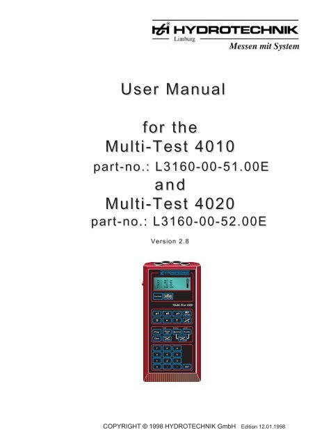
User Manualfor theMulti-Test 4010part-no.: L3160-00-51.00EandMulti-Test <strong>4020</strong>part-no.: L3160-00-52.00EVersion 2.8 2.6P1: =P2: =dP: =Q : =186,4 bar182,1 bar4,3 bar72,50 l/minContrastUnit TimeLanguageMulti Test <strong>4020</strong>p1 p2 p3p(p1-p2)QnITUscan memory printerProg.AbtastrateSpeicherDruckerClearminmaxStartStop7 8 94 5 61 2 30 , -- ENTCOPYRIGHT © 1998 HYDROTECHNIK -2-GmbH Edition 12.01.1998
PrefaceThe user manual in hand is a brief description of the handheld measuring instrument Multi-Test 4010 andMulti-Test <strong>4020</strong>, standard type, with the following measuring inputs:- 3 analog measuring inputs for pressure sensors with standardised input signal of 0 to 20 mAor 4 to 20 mA. It is possible to measure pressure (p1, p2 and p3) and pressure differential from p1 - p2.Instead of the pressure channel p3, the measurement of direct current or direct voltage can be selected.Additionally all extreme values can be shown separately in the display.- 2 separated frequency measuring inputs for pulse signals between 2 mV and 10 V for volume flow rateandrev. speed sensors. It is possible to measure volume flow rate and rev. speed.- Additionally in the Multi-Test <strong>4020</strong>: RS 232 interface for the connection to a PC.Real time clock for the printout with date and time.Should you have any difficulties in understanding nevertheless, please do not hesitate to contact us, we will doour best to help you.We reserve the right to make modifications, necessary for the technical progress.We wish you a lot of success for the usage of our handheld measuring instrumentMulti-Test 4010 and <strong>4020</strong>-2-
IndexGeneral ........................................................................................................................................1. User manual Multi-Test 4010/<strong>4020</strong> ...................................................................................1.1. Examples for a display ...........................................................................................................1.2. Initialisation ............................................................................................................................2. Programming of syntax and unit of measurement ...........................................................2.1 Addition to Multi-Test <strong>4020</strong>, programming of date and time ...................................................3. Programming of single measuring channels ....................................................................3.1 Programming of p1, p2 or p3 .................................................................................................3.2 Selection of pressure sensor .................................................................................................3.3 Input of calibration value .......................................................................................................3.4 Zero point alignment ..............................................................................................................455577888994. Programming of current- or voltage measurement .......................................................... 104.1 Selection of current- or voltage measurement........................................................................ 104.2 Input of calibration value ........................................................................................................ 104.3 Zero point alignment .............................................................................................................. 104.4 Selection of direct voltage measurement ............................................................................... 115. Programming of pressure differential measurement .......................................................6. Programming of volume flow rate "Q" ..............................................................................7. Programming of rev. speed "n" ..........................................................................................1112138. Programming of temperature "T" ....................................................................................... 139. Working with the min/max. memory ..................................................................................9.1 Measuring value display ........................................................................................................9.2 Display of min/max. values from p1 .......................................................................................9.3 Deletion of all min/max. values ..............................................................................................9.4 Deletion of single min/max. values .................... ...................................................................10. Programming of memory ....................................................................................................10.1 Storage of measuring values .................................................................................................10.2 Selection of measurable variables to be stored .....................................................................10.3 Start of storage ......................................................................................................................11. Programming and selection of printer ............................................................................... 1511.1 Tabular and graphical measuring value printout .................................................................... 1611.2 Selection of graph with manual scaling .................................................................................. 1612. Special functions in Multi-Test <strong>4020</strong> ..................................................................................12.1 Printout with date and time ....................................................................................................12.2 Measuring value transfer to PC .............................................................................................13. Technical annex ................................................................................................................... 1813.1 Connection of pressure sensors (no HYDROTECHNIK sensors) ......................................... 1813.2 Advice for mechanical connection of a pressure sensor ........................................................ 1813.3 Contrast adjustment of display .............................................................................................. 1813.4 Charging of internal battery ................................................................................................... 1814. Technical data of Multi-Test 4010 and <strong>4020</strong> ....................................................................... 1915. Information on guarantee .................................................................................................... 2013131313131414141417171716. Maintenance ........................................................................................................................20-3-
GeneralThe measuring instruments Multi-Test 4010 and Multi-Test <strong>4020</strong> of company HYDROTECHNIK GmbH, Limburgare efficient handheld measuring instruments for the measurement of pressure, pressure peaks, pressuredifferential, volume flow rate, rev. speed, temperature, direct current and direct voltage.Both instruments are equal in their technical data, except a serial interface (RS 232) in the Multi-Test <strong>4020</strong> forthe connection to a PC and a real time clock. The stored measuring values are equipped with date and time,what you can see later at the printout.Furthermore, the instruments dispose of 2 separated frequency inputs and 4 analog inputs. You can connectsensors with an output signal between 2 mV and 10 V to the frequency inputs and sensors with a standardisedoutput signal of 0 to 20 mA or 4 to 20 mA to the analog inputs.Therefore, sensors that were not produced by HYDROTECHNIK can also be connected, you only have to payattention to the above-mentioned output signals of the sensors.The sensor supply voltage from the measuring instrument is between 14,4 and 30 VDC (please see technicalannex on page 16).Besides this an external measuring adapter for the measurement of direct current or direct voltage can beconnected instead of the pressure measuring input p3.The fourth analog measuring input serves for the measurement of temperature with a Pt 100 resistor sensor in4-wire technique.Furthermore the measuring instrument has two independent memories, which acquire the extreme values of thesix measuring channels independently and store them afterwards.Another measuring value memory with a capacity of 60.000 measuring values allows the storage of a completeseries of measurements.The stored series of measurements can be printed out completely as a graph or as a table.The printout of a series of measurements is possible with a manual or an automatic scaling.The instrument supports the following printer types:- Epson 9-pin- Epson 24-pin- IBM-Proprinter- DPU 411- HP-Inkjet black/white- HP-Inkjet colour-4-
1. User manualMulti-Test 4010/<strong>4020</strong>1.1 Examples for a displayinitialisationversion 2.8p1= 143.2 barp2= 123.7 barp3= 98.0 barQ = 64.2 l/minp1= 143.2 barp2= 123.7 barp3= 98.0 barp1^ 25.3 I 198.5p1= 143.2 barp2= 123.7 barp3= 98.0 barQ = 64.2 l/minp2= 123.7 barp3= 98.0 barQ = 64.2 l/minT1= 23.6 °COn the keyboard you will find several keys, which you can onlypress in connection with another key. These are the keys min/max., Clear, Prog., Memory and Printer.In doing so you have to take into consideration that the periodbetween pressing the first and the second key must not belonger than three seconds. After three seconds the key pressedfirst will be ignored. If the user works in the input mode, thatmeans in the mode for the input of calibration values (sensorend value, calibration value for pulses/teeth per revolution, etc.),the figure values need to be entered with the number keyboard.You have to finish all inputs with "ENT".After having switched on the instrument, this menu will appearfor approx. three seconds.In this period the instrument can be re-initialised by pressing thekeys 1, 2 and 3 (the adjustment of standard values is describedlater in this manual).When switching the display on again, it will automatically showthe last adjustment before having switched off:simultaneous measurement and display of four measuringvalues, e.g. p1, p2, p3 and Q.If the extreme values (min/max.) of for example p1 min. and p1max. shall be shown, the lowest line will be exchanged, i.e. themin/max. values of pressure channel p1 are shown instead ofvolume flow rate Q.If the previous display with Q shall be shown again, the key"min/max." must be pressed and the lowest line will beexchanged another time. The volume flow rate measurementQ is shown again.If for example the temperature measurement T is selectedadditionally to p1, p2, p3, and Q, the displayed measurablevariables will move upwards, so that p1 disappears and theselected measurable variable "T" is displayed in the lowest line.1.2 InitialisationIt can happen, that the information in digital storage systems is distorted, due to very heavy electromagneticinterferences, which still can occur today in industrial plants.This shows itself in an amount of data that the user must consider unrealistic after a printout.For this case the instrument has the possibility to set all data back to a given state by a socalled re-initialisation.However all data like calibration value, syntax, units of measurement, output signal of the pressure sensors andall parameters, entered previously by the user, are deleted.initialisationversion 2.8You can start the re-initialisation by switching the measuringinstrument on and by entering the numbers 1, 2 and 3.-5-
new initialisationall parameters?ENT -> yes22.05.95unit language*1 : SI *3 :Germ.2 : US 4 : Engl.5 : FrenchSpecial functions onlyat Multi-Test <strong>4020</strong>* PROG DATE *13.06.95ENT -> confirm* PROG TIME *09 : 15ENT -> confirmBy pressing keyall data like calibration value, syntax,units of measurement, output signal of the pressure sensors,entered previously by the user, is deleted or reset to a work´sadjustment. At the Multi-Test <strong>4020</strong> date and time are deletedadditionally.The invocation into the menu point unit/syntax will followimmediately, where for example the SI-units and the Germanlanguage are selected previously. In this menu you canalready select your language as well as the requested units ofmeasurement by pressingthe corresponding number keys and by confirming yourselection with key .The date and the time can additionally be entered into the Multi-Test <strong>4020</strong>. When storing measuring values and printing themout later, all reports will bear the date and time.First of all you need to enter the date always with two digits(day/month/year), and confirm it with key "ENT".Immediately afterwards the menu for entering the time will bedisplayed. Please do this always with two digits, too. The clockis started as soon as key "ENT" is pressed.p1= cal ? barp2= cal ? barp3= cal ? barQ = cal ? l/minThis display is shown, in which the user can see that acalibration value, for example for the pressure sensors and thevolume flow rate, needs to be entered.We generally deliver our measuring instruments with deletedcalibration values.The input and modification of the necessary parameters isdescribed later on.Please follow the further operation steps in this manual.Should you have invoked a re-initialisation by mistake,you can leave this program by pressing any key,except key ENT, without having executed are-initialisation.-6-
2. Programming of syntaxand unit of measurement* * * * PROG * * * *1-> Unit/ Language2-> Date3-> Clockunit language*1-> SI * 3-> Germ.2-> US 4-> Engl.5-> FrenchThe stroke of key and key causes thismenu to appear.To select the unit/syntax you have to press key 1.You can choose between SI- and US-units.The SI-units are for example bar, °C, l/min., etc..After the switch-over to US-units, the usual units likepsi, °F, gal/min. are used.The languages German, <strong>English</strong> and French can be selected,the selection must be confirmed with key ENT. The star marksthe actual selection.2.1 Addition to Multi-Test <strong>4020</strong>,programmming of date and time* * PROG DATE * *19/06/95ENT-> confirmWith key 2 the menu "Prog. date" is invoked, into which you canenter the actual date, always with two digits: day-month-year.* PROG Clock *11 : 16ENT-> confirmWith key 3 the menu "Prog. time" is invoked, into which you canenter the actual time, always with two digits: hours-minutes.When pressing key "ENT" after this, the clock isstarted. The clock can be adjusted exactly by puttingit forward by one minute and starting it with key"ENT", whilst comparing it with another exact clock.-7-
3. Programming of singlemeasuring channels3.1 Programming of p1, p2 or p3* * * * PROG P1* * * *1: -> type of sensor2: -> calibration val.3: -> zero point3.2 Selection of pressure sensor* * * * PROG P1* * * **1-> 0 - 20 mA2-> 4 - 20 mAENT-> confirmBy pressing the keys and you will invoke thefollowing selection menu.As there is the possibility to connect pressure sensors with anoutput signal of 0 to 20 mA and 4 to 20 mA to the instrument, itis absolutely necessary to indicate the requested type of signal.For this, you have to select number 1 "Selection sensor type"out of the menu "programming p1".The following display is shown. In the example the signaltype 0 to 20 mA is chosen, number "1" is entered (have a lookat the star-symbol!) and key "ENT" is pressed for confirmation.Error signal at 4 to 20 mA sensorP1 : = - - - - - barP2 : = 0.0 barP3 : = 0.000 l/minMeasuring value display when4 to 20 mA sensors work correctlyP1 : = 0.0 barP2 : = 0.0 barP3 : = 0.0 barQ : = 0.000 l/minIf horizontal lines are shown in the display,(e.g. P1 : = - - - - - bar) this can have the following reasons:For example, the connections to the pressure sensors aremissing (measuring cable between sensor and measuring inputis missing), a parting of a cable or a defect of a sensoroccured, or the sensor isn´t connected to the measuring input,that means the measuring input isn´t provided with a currentsignal.Here the life-zero-detection is used to inform the user about theabove-mentioned error possibilities.If the sensor works correctly, the measuring value display isshown without the horizontal lines.This optical signal is only valif for the current signalsfrom 4 to 20 mA.Please take into consideration, that different current signals canbe adjusted for pressure sensors (p1, p2 and p3)e. g.: p1 = 4 to 20 mAp2 = 0 to 20 mA-8-
3.3 Input of calibration value* * * * PROG P1* * * *calibr. value: 600.0(bar)ENT-> confirmIf you enter the figure "2", the menu for the input of calibrationvalues will be opened.The corresponding measuring range end value, in this case 600(pressure measuring range end value of the pressure sensor),needs to be entered. Confirmation of the input with key "ENT".You can see the end value of the pressure measuring rangefrom the label of the pressure sensor.Please take into account, that, when measuringnegative pressure with a pressure sensor from -1 to 6bar, not the calibration value, referring to the pressuremeasuring range end value is entered, but the span ofthe pressure measuring range from -1 to 6 = 7 bar.That means, the number 7 must be entered as acalibration value.3.4 Zero point alignment* * * PROG P1 * * *sensor must bedepressurizedENT-> confirm* * * PROG P1 * * *alignment 2 sec.* * * PROG P1 * * *zero point : 0.184(bar)ENT-> confirmFor measurements of negative pressure and for precisemeasurements of pressure differential the user needs toexecute a zero point alignment for the connected pressuresensor.For doing this, you have to enter the number "3" in the abovemenu.The hint, that the sensor must be pressure free, is shown. Dueto this it is sensible to take the sensor from the plant. Press key"ENT".The alignment of the zero point correction is carried out.The display, shown on the left, is active for approx. 2 seconds,after this the instrument will show another menu point.In this display you can see the zero point deviation of thepressure sensor. With its confirmation by a stroke of key "ENT",it will be taken into account as a correction value for all furtherpressure measurements by the internal software.With another stroke of key "ENT" you will come back into theusual measuring value display.The measuring inputs p2 and p3 are programmed in the sameway as described above.-9-
4. Programming of current- orvoltage measurementIt is possible to measure current and voltage with the Multi-Test4010/<strong>4020</strong>.The adapters, necessary for this, have to be connectedexternally to the measuring input p3. The following current- orvoltage adapters can be applied:- Current adapter 1-channel,measuring range: 0 to + 2 A (direct current)calibration value to be entered: 4.0- Voltage adapter 1-channel,measuring range: 0 to + 48 V (direct voltage)calibration value to be entered: 100.0p1= 143.2 barp2= 123.7 barp3= 98.0 barQ = 64.2 l/minAfter having connected the corresponding current- or voltageadapter to the measuring input p3, you have to enter thecalibration value and to activate measuring channel p3.This is the already known measuring value display, from whichthe necessary steps are made.4.1 Selection of current- or voltagemeasurement* * * PROG U/ I * * *1-> current DC2-> voltage DC4.2 Input of calibration value* * * PROG U * * *calibr. value: 100.(V)ENT-> confirm4.3 Zero point alignment* * * PROG U * * *adapter must bewithout signalENT-> confirmBy pressing the keys and you will invoke thefollowing program routine.With the input of either "1" or "2" you can choose between themeasurement of current or of voltage. In the example, themeasurement of voltage is chosen with number "2".The following display appears.Now, the user is requested to enter the calibration value of theconnected voltage adapter. In this example the value is ä100ôand the figures 1 0 0 need to be entered one after the otherwithout any comma. Afterwards, confirmation with key "ENT".You may not connect the adapter with the voltage source to bemeasured, yet.The corresponding hint is shown in the display. Please presskey "ENT".* * * PROG U * * *alignment 2 sec.ENT-> confirm❖An automatic alignment will be carried out for approx. 2seconds and afterwards theinstrument will jump back into the first menu.The user can redefine the instrument for a measurement ofcurrent in the same way.* * * PROG U/ I * * *1-> current DC2-> voltage DC ❙Please take into account, that you can not measurecurrent and voltage at the same time, as only themeasuring input p3 is available for this !p1= 143.2 barp2= 123.7 barp3= 98.0 barQ = 64.2 l/minAnother stroke of key "ENT" leads back to the measuring valuedisplay.-10-
4.4 Selection of direct votagemeasurementp1= 143.2 barp2= 123.7 barU1= 0.00 VQ = 64.2 l/minp1= 143.2 barp2= 123.7 barp3= 98.0 barQ = 64.2 l/min❖3. Zeile❖To finally carry out a direct voltage measurement, you have topress key .The third line of the display for the measurement of voltage isactivated.In doing so you have prepared the voltage adapter formeasuring voltage with help of the pressure channel p3.Remark:By pressing either key or you canselect between pressure- and voltage measurement.Only the corresponding pressure sensor or adapterneeds to be connected to the measuring input p3.The calibration values entered previously, remain inthe instrument.If you request a measurement of current, you will have to act inthe same way as for themeasurement of voltage.5. Programming of pressuredifferential measurementPrecise pressure differential measurements are only possible, ifboth pressure sensors have been aligned before, on onepressure level, at which the later measurement shall be made.For this, both pressure sensors p1 and p2 have to bemechanically connected to the same pressure level via adistributor (see scheme: pressure differential alignment).* * * PROG DP * * *alignment P1/P2 withthe same pressure!ENT-> confirmYou can invoke the alignment of the pressure sensors by thestroke of key and key.The following display appears. The alignment is started by theconfirmation with "ENT".-11-
* * * PROG DP * * *balancing* * * PROG DP * * *dP-correction: -0.19(bar)ENT-> confirmThe word "alignment" will be displayed for approx. 3 seconds.The display will show the correction value, which will be takeninto account at all later measurements of pressure differential.To get back into the measuring value display, you have to presskey "ENT". After the alignment the pressure sensor p2 needs tobe mechanically connected to connection B (see scheme:pressure differential alignment, page 10).Now you can carry out precise pressure differentialmeasurements without influencing the sensor deviations,temperature drifts and offsets.Please take into consideration, that the pressuredifferential is only displayed with correct signs, whenthe higher pressure is at the pressure sensor p1(delta-p = p1-p2).6. Programming of volumeflow rate "Q"Before volume flow rate sensors can be connected, theirspecific calibration value must be entered. This enables themeasuring instrument to correctly calculate, for example l/min.With a stroke of the keys and the following* * * PROG Q * * *1-> turbine/GFM2-> orifice gaugedisplay is shown.The invocation for a turbine and for a gear flow meter is thesame.In the example "Turbine" is selected with the input of figure "1".* * * PROG Q * * *(turbine/GFM)calibr. value: 24.85ENT-> confirm* * * PROG Q * * *1-> turbine/GFM2-> orifice gaugeAnother menu is displayed immediately, which requests theinput of a calibration value.You can see this value either from the label of the turbine orfrom the calibration certificate, belonging to the turbine.You always have to enter the complete value with decimal point,in this example it is the value 24,85. The input needs to beconfirmed with key "ENT".The instrument jumps back into the first menu.If an orifice gauge shall be used, you will have to enter thefigure "2" in this menu.* * * PROG Q * * *1-> A3 2-> B3*3-> C3ENT-> confirmThe following display will appear, in which you can selectbetween three flow ranges and three types respectively.You can see the type of the orifice gauge from its label.In the example type C3 is selected by the input of figure "3".The "star"-symbol will appear in front of the figure.Please press key "ENT" for confirmation.-12-
7. Programming of rev. speed "n"* * * PROG n * * *pulses/revolutionI : 60ENT-> confirmAfter a stroke of the keys and , you will seethe following menu, in which the adjusted value for pulses perrevolution is shown.Here it is possible to enter several pulses per revolution, forexample up to 60 pulses for gear rings. The desired number ofpulses is entered as usual as a number and confirmedwith key "ENT".8. Programming of temperature "T" A programming of the temperature is not necessary,as temperatures between -50 and +200 C can bemeasured.Now, you have entered all needed calibration values for thesensors and after a corresponding selection of the measurablevariables you can execute measurements.9. Working with the min/max. memory Generally all measuring values are stored as extreme values(min/max. values) in the background and displayed, if9.1 Measuring value displayrequested.All extreme values can be displayed in the fourth line, but onlyone after the other.p1= 143.2 barp2= 123.7 barp3= 98.0 barQ = 64.2 l/min9.2 Disply of min/max. values from p1p1= 143.2 barp2= 123.7 barp3= 98.0 barp1^ 25.3 I 198.5Starting at the well-known measuring value display, shown onthe left side, you can have the min/max. values of for examplep1 be displayed by pressing the keys and .In the fourth line the min/max. value of p1 is shown.The activation of keyremoves the display of themin.- valuemax.- value9.3 Deletion of all min/max. values in memoryp1= 143.2 barp2= 123.7 barp3= 98.0 bar*DEL ALL MIN/MAX*min/max. values and shows the previous measuring valuedisplay with the measuring value display Q = 46,2 l/min.By pressing key and you can delete thecomplete content of the min/max. memory. The display showsthe following message for approx. 3 seconds.9.4 Deletion of single min/max. valuesp1= 143.2 barp2= 123.7 barp3= 98.0 bar* DEL MIN/MAX P1**p1= 143.2 barp2= 123.7 barp3= 98.0 barp1^ 0.00 I 143.2The min/max. value of for example p1 can be deleted with astroke of the keys and . The message on theleft appears for approx. 3 seconds in the lowest line of thedisplay.After this, the display will automatically jump back into themin/max. value display of p1.-13-
10. Programming of memory10.1 Storage of measuring valuesscan. rate1 : 1 4 : 500*2 : 10 5 : 10003 : 100 6 : 10000* * * storage time * * *10 : 00 minBefore you can carry out a storage, you need to adjust thescanning rate. If the signals to be measured are very fast, likefor example at the acquisition of pressure peaks, a scanningrate between 1 and 10 ms is recommended.However the volume flow rate can still be measured with ascanning rate of 100 ms.A stroke on the keys and leads directly intothe menu for selecting the scanning rate. In the example ascanning rate of 10 ms was selected (star-symbol in front offigure 2).Please confirm your selection with key "ENT".Directly afterwards the instrument will show how long themeasurement may take.Please take into account, that a storage time isindicated which is still existing from a previousselection, in this case of the measurable variable p1.10.2 Selection of measurable variablesto be storedPROG MEMORY* p1 p2 p3 T* Q n dpENT-> confirmIf you press the keys and , the menu forselecting the measurable variable to be stored will appear.In this example we have chosen p1 and Q (star !).You select the two measuring channels by a stroke* * * storage time * * *3 : 20 minof key and of key and activate them bypressing key "ENT". A new message concerning the maximalpossible duration of the storage is displayed.10.3 Start of storage* p1= 143.2 barp2= 123.7 barp3= 98.0 bar* Q = 64.2 l/minAfter having selected the scanning rate (ms) and themeasurable variables (p1 and Q) the storage is started directlywith the keys and .The following display with optical memory status display isshown. Please pay attention to the star-symbols in front of themeasurable variables, too.You can interrupt the storage any time with key or it isautomatically stopped when the memory is full.-14-
11. Programming or selection of a printer As the connected printer needs to be tuned to themeasuring instrument, the correct printer type needsto be selected before the printout is made.* PRINTERTYPE *1:EPSON- 9 4:DPU2:EPSON-24 5:HPs/w3:IBM-PRO 6:HP colWhen selecting a Hewlett-Packard printer, youshould take the following into consideration:Due to the variety of HP-printers of series Deskjet,you should indicate first of all, if the printout shall bein black/white or in colour.Afterwards you should select the correspondingprinter type (only valid for HP-printers).In the following example, the printer selection isdescribed in more detail:By pressing the keys and , theprinter drivers that are supported in the measuringsystem are displayed:1. Epson 9-pin printer2. Epson 24-pin printer3. IBM-Proprinter4. DPU 4115. HP-Deskjet black/white6. HP-Deskjet colourAs an example, the printer type no.: 6 = HP col.(colour) is selected by an input of the number 6.* PRINTERTYPE *1:EPSON- 9 4:DPU2:EPSON-24 5:HPs/w3:IBM-PRO *6:HP colIn the display the star-symbol is shown in front of thenumber (*6).By pressing keyyou will automatically getinto the display for the selection of the printer type(HP-printer type).* PRINTERTYPE **1 : HP 320/3402 : HP 500/5200 : moreThis selection is only possible forthe HP-printers.In the example, type „HP 320/340“ is selected byentering the number „1“.The star-symbol will appear in front of the number(*1).With keythe selection will be finished andthe requested printer will be activated.** PRINTERTYPE **3 : HP 400/540/600660/8900 : morePlease enter "0", if you require the display of furtherHP-printer types: " 3 : HP 400/540/600/660/890 ".With a stroke of key "3", these printer types areselected.By pressing key "0" you will return to the previousmenu.-15-
11.1 Tabular and graphical measuring valueprintoutprint mode Scal.1: Table 3: AUTO2: Graphic 4: MANENT-> confirmWith a stroke of the keys and youcan select the print mode, either as a table or as agraph, as well as the automatic or manual scaling ofthe measuring values.At the automatic scaling it can happen,in the most unfavourable case however,that several curves superpose eachother (congruence) in the graphicaldisplay.Therefore we recommend to selectmanual scaling in this case.If you choose the tabular format, all selectedmeasurable variables are printed out in numbercolumns.11.2 Selection with graph with manual scaling* * Scaling P1 * *Minval.: 10 barMaxval.: 150 barENT-> confirm* * Scaling Q * *Minval.: 20 l/minMaxval.: 70 l/minENT-> confirmAfter having entered the figure 2 for graph and 4 formanual scaling and after confirmation with key"ENT", you will see the following display.In the former example the measurable variables p1and Q were selected during the storage. Now, theinstrument automatically requests the input forscaling p1.As an example, the min. value 10 bar and the max.value 150 bar are entered andconfirmed with key "ENT".The instrument automatically requests now the inputfor the scaling of Q.We have chosen 20 l/min. as a min. value and70 l/min. as a max. value and confirmed the inputwith key "ENT".-16-
* * PRINTING * *(DPU 411)ENT-> confirm* * PRINTING * *(DPU 411)0%* *PRINTING * *(DPU 411)PRN ERRORThe hint, that the printer is ready, is displayedimmediately afterwards.Furthermore the selected printer is shown again:(DPU 411).With a stroke of key ENT you will start the printer.In the lowest line of the display the measuring data,already transferred to the printer, are shown in %. Allmeasuring data were transferred to the printer, whenthe display shows "100%".If the printer cable between printer andmeasuring instrument is not connected,the warning "PRN ERROR" will appear inthe display.If then the connection between printer and measuringinstrument is made, the printoutwill be started again with a stroke of key "ENT".A printout can always be interrupted with key !12. Special functions in Multi-Test <strong>4020</strong>12.1 Printout with date and timeAt the Multi-Test <strong>4020</strong> the date and the time of the actual storage are added to the printout.This guarantees an additional security for the user by confirming the date and time when the measurement wasexecuted.12.2 Measuring value transfer to PC and adjustment of the BaudrateAt the Multi-Test <strong>4020</strong> all stored measuring values can directly be transferred to a PC via the serial interface.For this, the software HYDROcomsys, developed by HYDROTECHNIK, is available. It serves for the processingof large amounts of data with graphical and tabular preparation and measuring value analysis and theirpresentation directly on the PC.Adjustment of the BaudrateBy pressing the key combination:and* * PROG RS232 * *1-> 9600 Baud2-> 19200 Baud3-> 38400 Baudthe corresponding Baudrate can be adjusted as aspeed of the data transmission from the measuringinstrument to the PC.The modification is made by pressing one of the keysfrom 1 to 3.After having selected the Baudrate you should pressBaud (Bd)Unit for speed of datatransmission1 Baud = 1 bit/skey-17-for confirmation.
13. Technical annex13.1 Connection of pressure sensor (no HYDROTECHNIK sensor)Generally, each pressure sensor that was not produced by HYDROTECHNIK can beconnected to the Multi-Test 4010/<strong>4020</strong> instruments, if:- the supply voltage of the sensor is between 10 and 30 VDC.- the necessary current output signal of the pressure sensor is 0 to 20 mA or 4 to 20 mA,where 20 mA must correspond to the pressure measuring range end value.- the correct polarity or the connection of the sensor is made to the signal measuringinputs p1, p2 and p3 of the measuring instrument.- the power supply of the sensor can drive the internal load resistance of 100 Ohmof the measuring instrument.13.2 Advice for mechanical connection of a pressure sensorAs HYDROTECHNIK’s pressure sensors are usually mechanically connected via direct adapters to theMINIMESS couplings of the system and as, due to this, an easy separation is always possible, even underpressure, this method is absolutely ideal for pressure sensors up to 630 bar.When using pressure sensors with a measuring range that is larger than 630 bar, you can not connect them viaMINIMESS couplings, but you have to connect them directly to the system.13.3 Contrast adjustment of a displayUnder certain circumstances it can happen, that the display of the measuring instrument is not readable anymore.This exceptional state could be caused by extreme temperatures, e.g. insolation directly on the instrument,storage in the car or influences by very low temperatures.Please try to make the display readable again by constantly pressing the contrast key.13.4 Charging of internal batteryIf you use the measuring instrument only from time to time it is sensible to charge the internal battery beforemeasuring. It is completely charged after a charging time of 14 to 16 hours.-18-
14. Technical data of Multi-Test 4010 and <strong>4020</strong>(reference of the specified data 20 °C ±3 °C)Measuring inputs:4 input jacks (Amphenol-Tuchel)2 x 8 poles for pressure (signal input: 0 to 20 mA, changeable to4 to 20 mA by internal software)and temperature (Pt 100, 4-wire technique)2 x 5 poles for volume flow rate or rev. speedautomatic change-over of the sensitivity:1 to 5000 Hz (low sensitivity 5 to 10 V)50 to 5000 Hz (high sensitivity 2 to 300 mV)Measuring ranges:Pressure: -1 to 1000 barTemperature: -50 C to +200 CVolume flow rate: 5-digit display with floating decimal point(depending on the measuring range of the volume flow ratesensor)Rev. speed: from 60 min-1 on, display 5-digits (referring to onescanning marking)Measuring rate:Resolution A/D-converter:Analog inputs:Digital inputs:12 bitpressure and temperature 1 msbetween 1 Hz and 60 Hz a singlemeasurement of the period durationis carried out. From 60 Hz on the measuringtime is constant = 16 ms.Extreme value memory:Measuring value memory:Data protection:Display:Interfaces:Power supply:Min/max. value storage of all measuring channels in thebackground, display by a keystroke.Max. 60.000 measuring values (depending on the selectedmeasurable variable) with selectable scanning rate 1, 10, 100,500, 1000 and 10000 ms.Battery-buffered RAM-memory against data loss4 lines LCD, height of the digits: 4,24 mm, display of measuringvalues: 4 linesCentronics für Drucker (4010 und <strong>4020</strong>)RS 232 für PC-Anbindung (nur <strong>4020</strong>)Internal 14,4 V NiCd-battery, 0,7 Ah for approx. 5 hourscontinuous operation with integrated battery-charger andbattery warning device. External voltage supply via powersupply unit 230 VAC/24 VDC or via any external voltage supplyunit (stabilised 24 to 30 VDC)Ambient conditions:Generally:Operational temperature: 0 C to +50 C,relative humidity: < 80%Housing material: ABS-plasticDimensions: 252x121x50 mm (LxWxH)Weight: 0,95 kgTechnical modifications are subject to change without notice.-19-
15. Information on guaranteeWithin the framework of our guarantee conditions we guarantee the unobjectionable manufacture of ourtechnical instruments.The guarantee is valid for 6 months.In principle, the general terms of business are valid.The right to claim under guarantee becomes invalid, when reparations or interventions are executed by persons,who were not authorised by us.Within the six months of the guarantee, we will remove free of charge damages or defects, which can be provedto be based on a work’s mistake, as far as the customer informs us immediately after having detected it, butwithin six months at the latest.The fulfilling of the guarantee is done in a way, that defect parts are repaired or replaced by unobjectionableparts at our choice, free of charge.Instruments, for which you want to claim under guarantee, have to be sent carriage paid to:HYDROTECHNIK - Kundendienststelle16. MaintenanceYour measuring instrument is a precision instrument, which guarantees an unobjectionable operation for manyyears, when treating it correspondingly.However, in the case that interferences occur nevertheless, please do not try to repair the instrument byyourself!Leave the maintenance or the reparation up to ourHYDROTECHNIK - KundendienststelleAddress:HYDROTECHNIK GmbHHolzheimer Straße 94 - 96D-65549 LimburgTel.: 0 64 31 - 40 04 · 0Fax 0 64 31 - 4 53 08L3160-00-51.00E/ L3160-00-52.00E / Multi-Test 4010/<strong>4020</strong> - 23.07.1998-20-
HYDROTECHNIK - ServiceLimburgMessen mit SystemHYDROTECHNIK GmbHHolzheimer Straße 94 - 96D-65549 LimburgTel.: 0 64 31 - 40 04 · 0Fax 0 64 31 - 4 53 08Should your Multi-System 5000 require repair, we depend on your support.Please describe your complaint as precisely as possible. That enable us to locate the error more easily and you willprofit from shorter repair times.If we have any additional queries, please state the person to contact:Company:Department:Name:Telephone:Fax:Please tick the appropriate answer:Part to repaired:Your PCoperating systemsoftwareMeasuring instr.SensorCableSupply unit386486PentiumP 2DOSWindows 3.1x orWindows 95NTHYDROcomsys/DOS:versionHYDROcomsys/Windows:versionHow to describe an error:Please leave all parameters etc. unchanged after an error occurs.Briefly describe your measuring task, connection of sensor, parameter adjustments (for example memory parameters,trigger, how many measuring values are acquired, type of printer, etc.Your description:
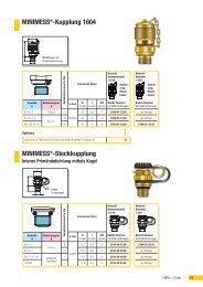
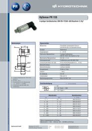
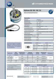
Order data for the Multi-Test 4010 and <strong>4020</strong>- Handheld measuring instrument Multi-Test 4010- Handheld measuring instrument Multi-Test <strong>4020</strong>Adapter 230 VAC / 24 VDC / 340 mAAdapter 115 VAC / 24 VDCAlternating battery 14,4 VDC / 700 mAhPart-number3160-00-51.003160-00-52.008812-00-00.198812-00-00.208873-02-00.02Sensors- Pressure (output signal: 4 to 20 mA) Measuring range 0 to 60Pressure sensor type HD in bar (psi) 0 to 2000 to 4000 to 600Pressure sensor type PR 15 -1 to + 60 to 1000(... 870)(... 2900)(... 5800)(... 8700)(-14,5... 87)(... 14500)3403-21-A4.373403-10-A4.373403-15-A4.373403-18-A4.373403-32-71.373403-29-71.37To select pressure sensors with 0 to 20 mA, the last two numbers of the order-no. need to be changed from 37 into 33 e. g.3403-xx-xx .33- Pressure (output signal: 0 to 20 mA) 0 to 60p/T-dual sensor for the simultaneous measurement of pressure 0 to 600and temperature (signal output T = 4-wire technique)with integrated direct connection for p/T-measuring couplingscrew series 1620 - M 16 x 2 (ident.-no. 04)- Volume flow rate Measuring range 7,5 to 75Measuring turbine RE 3 in l/min (gal/min) 15 to 300Output signal (square wave) 25 to 600with MINIMESS and p/T-coupling (series 1620)(Please see our brochure "Measuring turbines RE 3 / RE 4" for further technical details)- Volume flow rate Measuring range 1,0 to 10Measuring turbine RE 4 in l/min (gal/min) 7,5 to 75Output signal (square wave) 15 to 300with MINIMESS and p/T-coupling (series 1620) 25 to 600(Please see our brochure "Measuring turbines RE 3 / RE 4" for further technical details)(... 870)(... 8700)(2... 20)(4... 79)(6,6... 158,5)(0,26... 2,6)(2... 20)(4... 79)(6,6... 158,5)3152-04-34.613152-03-34.6131V7-21-35.0031V7-30-35.0031V7-40-35.0031V7-01-35.0031V7-70-35.0031V7-71-35.0031V7-72-35.00- Volume flow rate Measuring rangeGear flow meter type GFMin l/min (gal/min)Output signal (square wave)with MINIMESS and p/T-coupling (series 1620)(Please see our brochure "Gear flow meter GFM" for further technical details)0,005 to 10,05 to 50,2 to 300,7 to 703,0 to 300(0,0013... 0,25 )(0,013... 1,3 )(0,05... 8 )(0,18... 18,5 )(0,79... 79,25)3143-01-35.003143-02-35.003143-03-35.003143-04-35.003143-05-35.00- Volume flow rate Measuring range 10 to 50Orifice gauge with MINIMESS screw coupling series 1620 in l/min (gal/min) 40 to 210Acquisition of the volume flow rate through measurement 120 to 600of the pressure differential with two pressure sensors andevaluation software in the Multi-Test 4010/<strong>4020</strong>(Please see our data sheet "Orifice gauge" for further technical details)- Temperature, Pt 100 -4-wire technique Measuring range -50 to + 200for p/T-coupling series 1620 (ident.-no. 04)in °C (°F)- Surface sensor, Pt 100 -4-wire technique- Rev. Speed, infrared-sensor type DS 03 Measuring range 1 to 9999with 25 pieces of reflective foilin min -1 (rpm)- Reflective foil (spare parts, 50 pieces)- Inductive transducer with amplifier, output signal: square wave (measurement of rev. speed on gear wheels)( 2,64... 13,21)(10,57... 55,48)(31,7... 158,5 )(-58... +392)3125-03-03.003125-03-06.003125-03-09.003949-04-01.003170-01-02.003130-02-01.008840-02-01.013107-00-09.00
AccessoriesPart-number- Measuring cable MK 01 (length 2,5 m) for the connection to pressure-, 8824-91-02.50rev. speed-, temperature- and volume flow rate sensors- Divider cable TK 07 (length 20 cm) always necessary for the measurement of pressure and temperature, max. 2pcs. 8824-A1-00.20- Measuring cable MK 13 (length 2,5 m) for the direct connection between measuring input and p/T-dual sensor 8824-A2-02.50- Connection cable (length 5 m) for external batteries 8824-64-05.00- Transport case (plastic box) 3160-00-16.01- Transport case I 3160-00-17.01- Transport case II (with additional cover and space for printer) 3160-00-18.07- Leather shoulder strap for Multi-Test 4010/<strong>4020</strong> 8875-03-00.01- Inkjet colour printer battery operation with ink cartridges and adapter (100 to 240 VAC - 50/60 Hz) 8865-01-13.00- Spare part ink cartridge in black 8865-01-09.01- Spare part ink cartridge in colour 8865-01-10.01- Data communication cable Centronics 36-poles/25-poles 8824-36-02.00- Direct connection for pressure sensor type HD - straight (series 1620 - M 16 x 2) 2103-07-08.62- Direct connection for pressure sensor type HD - 90° (series 1620 - M 16 x 2) 2146-13-05.00- Direct connection for pressure sensor type PR 15 - straight (series 1620 - M 16 x 2) 2146-05-30.00- Direct connection for pressure sensor type PR 15 - 90° (series 1620 - M 16 x 2) 2146-54-19.40- p/T-measuring coupling 1620 (ident.-no. 04) screw-in thread M 10 x 1 2149-04-19.13- p/T-measuring coupling 1620 (ident.-no. 04) screw-in thread ISO 228-G 1/4 2149-04-15.13additional measurement of direct voltage or direct current possible- Voltage (external connection adapter) with signal output 0 to 20 mA Measuring range 0 to ±48 VDC 3160-00-00.22- Current (external connection adapter) with signal output 0 to 20 mA Measuring range 0 to ± 2 ADC 3160-00-00.23Software support for Multi-Test <strong>4020</strong> for the display and evaluation of measuring values on PC-XT/AT/PS/2- HYDROcomsys/DOS software package (from DOS 4.0 on) diskette 3 1/2" German 8874-01-01.02included in the delivery range diskette 3 1/2" <strong>English</strong> 8874-01-01.05- HYDROcomsys/Win software package (windows version) diskette 3 1/2" German 8874-01-01.19included in the delivery range diskette 3 1/2" <strong>English</strong> 8874-01-01.20- Data communication cable for RS 232 9-poles / 9-poles 8824-43-02.009-poles / 25-poles 8824-44-02.00