Oakton StableTemp Ovens Manual
Oakton StableTemp Ovens Manual
Oakton StableTemp Ovens Manual

You also want an ePaper? Increase the reach of your titles
YUMPU automatically turns print PDFs into web optimized ePapers that Google loves.
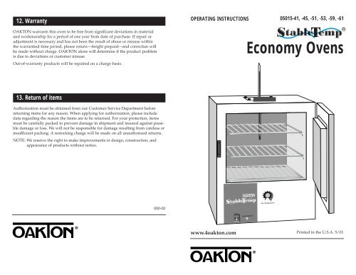
23104561079812. WarrantyOPERATING INSTRUCTIONS05015-41, -45, -51, -53, -59, -61OAKTON warrants this oven to be free from significant deviations in materialand workmanship for a period of one year from date of purchase. If repair oradjustment is necessary and has not been the result of abuse or misuse withinthe warrantied time period, please return—freight prepaid—and correction willbe made without charge. OAKTON alone will determine if the product problemis due to deviations or customer misuse.Out-of-warranty products will be repaired on a charge basis.Economy <strong>Ovens</strong>13. Return of itemsAuthorization must be obtained from our Customer Service Department beforereturning items for any reason. When applying for authorization, please includedata regarding the reason the items are to be returned. For your protection, itemsmust be carefully packed to prevent damage in shipment and insured against possibledamage or loss. We will not be responsible for damage resulting from careless orinsufficient packing. A restocking charge will be made on all unauthorized returns.NOTE: We reserve the right to make improvements in design, construction, andappearance of products without notice.000-00Set Temperaturewww.4oakton.comPrinted in the U.S.A. 5/01
Table of Contents1.0 Introduction .....................................................................................................................42.0 Receiving and Inspection .............................................................................................42.1 Inspection .......................................................................................................................42.2 Accessories .....................................................................................................................43.0 Installation ...................................................................................................................5-63.1 Power Source .................................................................................................................53.2 Location ..........................................................................................................................53.3 Lifting / Handling ........................................................................................................53.4 Leveling..........................................................................................................................53.5 Cleaning .........................................................................................................................64.0 Control Panel Overview ...............................................................................................74.1 Power ..............................................................................................................................74.2 Temperature Controller................................................................................................74.3 Heating Light.................................................................................................................75.0 Precautions.......................................................................................................................86.0 Operation..........................................................................................................................96.1 Power Supply ................................................................................................................96.2 Setting Main Temperature ...........................................................................................97.0 Maintenance...................................................................................................................107.1 Cleaning........................................................................................................................107.2 Storage ..........................................................................................................................108.0 Troubleshooting.......................................................................................................11-138.1 Temperature ............................................................................................................11-128.2 Mechanical ...................................................................................................................138.3 Other .............................................................................................................................139.0 Parts / Accessories ........................................................................................................1410.0 Specifications..............................................................................................................1511.0 Wiring Diagram ....................................................................................................19-2012.0 Warranty.......................................................................................................................2413.0 Return of Items...........................................................................................................242 3
1. IntroductionThank you for purchasing an OAKTON ® <strong>StableTemp</strong> ® Economy Oven! These unitsare general purpose gravity convection ovens for professional, industrial or educationaluse where the preparation or testing of materials is done at approximatelyatmospheric pressure and no flammable, volatile, or combustible materials are beingheated. These units are not intended for hazardous or household use.Your satisfaction and safety require a complete understanding of this unit. Read theinstructions thoroughly and be sure all operators are given adequate training beforeattempting to put the unit in use. Note that this equipment must be used only for itsintended application; any alterations or modifications will void your warranty.See back page of this manual for more warranty information.2. Receiving and Inspection2.1InspectionThe carrier accepts responsibility for safe delivery and is liable for loss or damage.On delivery, inspect for visible exterior damage. Describe and note on the freight billany damage found on the shipping carton or unit and enter a claim on the form suppliedby the carrier.Inspect for concealed loss or damage on the unit itself. If any damage is found thecarrier will arrange for an official inspection to substantiate your claim.If for any reason you must return the unit, authorization must be obtained from ourCustomer Service Department. See the back page of this manual for more informationon return of items.2.2AccessoriesVerify that all of the equipment indicated on the packaging slip is included with theunit. Carefully check all packaging before discarding. Each unit is equipped with 2adjustable shelves, 8 shelf clips, a spirit-filled glass thermometer, and a 6-ft, threewireline cord. The 120 VAC models also include a plug.3. InstallationLocal city, county or other ordinances may govern the use of this equipment. If youhave any questions about local requirements, please contact the appropriate localagency. Installation may be performed by the end user. It is unnecessary for this unitto be installed by a technician.Under normal circumstances this unit is intended for use inside, at room temperaturesbetween 5°C and 40°C, at no greater than 80% relative humidity (at 25°C) andwith a supply voltage that does not vary by more than 10%. Customer Serviceshould be contacted for operating conditions outside of these limits.3.1Power SourceThe electrical supply to the unit must conform to all national and local electricalcodes. The power source must match the voltage, cycle, phase and ampere requirementslisted on the data plate (located just above the power cord on the back side ofthe oven) This unit is intended for 50/60 HZ application. Make sure your powersupply matches that shown on the data plate. The voltage of the outlet should notvary more than 10% from the dataplate rating. A separate circuit is recommendedto preclude loss of product due to overloading or circuit failure.3.2LocationWhen selecting a site for the oven, consider conditions that may effect performance,such as heat or cold from air vents, fast moving air currents, other ovens, autoclaves,direct sun, etc. Avoid high traffic areas that may reduce accessibility to the oven andallow at least 5 cm between the unit and surrounding walls or partitions that mightobstruct free airflow.3.3Lifting / HandlingThese units are heavy and care should be taken to use appropriate lifting devicesthat are sufficiently rated for these loads. Units should only be lifted from their bottomsurfaces. Doors, handles, and knobs are not adequate for lifting or stabilization.The unit should be completely restrained from tipping during lifting and transport.All moving parts, such as shelves and trays should be removed and doors need to bepositively locked in the closed position during transfer to prevent shifting and damage.3.4LevelingThe unit must sit level and solidly. The oven is equipped with non-adjustable rubberfeet to raise it off the counter and prevent sliding; however, the counter must belevel to provide optimum working and safety conditions.45
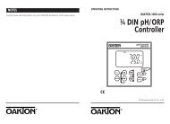
2314056107983.5CleaningThe oven was cleaned at the factory, but not sterilized. Remove all interior parts,including shelves and shelf clips if assembled and clean the inside of the chamberthoroughly with a disinfectant that is appropriate for your application. DO NOTUSE chlorine-based bleaches or abrasive cleaners, as they will damage the ovensinterior surfaces. DO NOT USE spray cleaners that might leak through openingsand cracks and get on electrical parts or that may contain solvents that will harmcoatings. A regular periodic cleaning is recommended.WARNING: Never clean the unit with alcohol or flammable cleaners with the unitconnected to the electrical supply. Always disconnect the unit from the electricalservice when cleaning and assure all volatile or flammable cleaners are evaporatedand dry before reattaching the unit to the power supply.4.0 Control Panel OverviewFigure 2: Control PanelSet Temperature3.6ShelvesPlace shelves in the chamber at desired position. See Figure 1.PowerHeat ActivatedFigure 1:Shelf location where desired.(2) provided.4.1PowerThe main power I/O (on/off) switch controls all power to the oven. It must be inthe I, or ON position, and illuminated before any systems are operational.4.2Temperature ControllerMarked Set Temperature, this control is equipped with an adjustment knob and agraduated dial. The graduated dial is marked with 10 major increments and 50minor increments. The increments can be used as index points for setting andreturning to set point temperatures.Squeeze clip and insertinto slots. Clip will haveto be tipped into thetop slot and then rolledinto the bottom slot4.3Heating LampA green pilot light marked Heat Activated illuminates when the heating element hasbeen activated and is heating. When set point is reached the pilot light will cycle onand off as the elements maintain the set temperature.Clip/Shelf interface (4) clips per shelf.Install clips at same elevation for each clip67
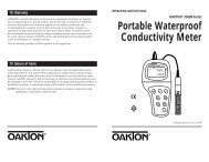
5.0 PrecautionsThis unit has been designed with a dampered vent from the chamber. In order towork effectively and safely, some precautions will need to be taken by the operator.• In most applications, the exhaust damper will need to be open during drying ordegassing for best results.• This oven is not an explosion proof oven and is not designed to handle combustiblegasses. Do not place explosive, combustible or flammable materials intothe chamber.• Some of the out-gassed byproducts may be hazardous or unpleasant to operatingpersonnel. If this is the case, the exhausts should be positively ventilated to theoutside and dealt with according to local regulations. Your dealer can provideyou with a power exhaust that greatly helps under these applications.• Do not place sealed or filled containers in the oven chamber.• This oven is NOT designed for use in Class I, II, or III locations as defined by theNational Electrical Code.• This oven is not intended, nor can it be used, as a patient connected device.6.0 Operation6.1Power SupplyThe power supply must be properly grounded (earthed) and correctly sized tomatch the unit data plate rating. The supply voltage must match the data platevoltage within 10%. If supplied with a detachable cord set, plug the female endinto the inlet on the unit and the male plug into the supply. Assure that unitsrequiring a fuse have a fuse installed.Push the power switch to the ON position and turn the Over TemperatureThermostat to its maximum position, clockwise so it will not interrupt the setting ofthe Main Temperature control.Figure 3: Placement of new thermometer clipThis section clamped underthe top platePinch these points after installation tocreate friction pressure on thermometerThis section clamped under the top plateLoosen screws, slide clipbetween top cover and bodywhere shown and retightenscewsNote: use caution when closing damperto avoid breaking thermometerclip installed6.2Setting Main TemperaturePlace the reference thermometer through the exhaust port on top of the unit; a clip isprovided with your accessory package. See Figure 3.The operating range for this oven is ambient room temperature + 5°C to 200°C. Toset the Main Temperature Controller turn the knob to the desired oven temperature,using the graduated dial as a reference guide. Allow one hour for the temperatureto stabilize. Using the reference thermometer, verify the oven temperature; if it isnot at the desired value, turn the control knob up or down as needed. Allow thetemperature to re-stabilize, continuing the process until the exact desired temperatureis achieved.Note: Slight vapor or smoke may occur in the initial heat-up. This is a normal occurrencewhen the oven is first brought up to temperature and protective coatings onthe element become hot.89
7.0 Maintenance8.0 TroubleshootingNote: Prior to any maintenance or service on this unit, disconnect service cord fromthe electrical supply source.8.1Temperature7.1CleaningClean the oven interior on a regular basis. When washing interior of unit, handlegasket carefully so as not to impair the positive seal. Clean the inside of the chamberthoroughly with a disinfectant that is appropriate for your application. Makesure to rinse the cleaned surface with a damp cloth. DO NOT USE chlorine-basedbleaches or abrasive cleaners, as they will damage the oven chamber. DO NOT USEspray cleaners that might leak through openings and cracks and get on electricalparts or that may contain solvents that will harm coatings.WARNING: Never clean the unit with alcohol or flammable cleaners with theunit connected to the electrical supply. Always disconnect the unit from the electricalservice when cleaning and assure all volatile or flammable cleaners are evaporatedand dry before reattaching the unit to the power supply.7.2StorageIf the unit is to be shut down for an extended period of time, wipe the chamberclean and let dry before closing door to eliminate possibility of contamination. If theunit is to be transported, remove shelving and trays, clasp the door shut and disconnectthe power supply. Please refer to Section 3.3, Lifting / Handling for furtherdirection.No maintenance is required on the electrical components. If oven fails to operate asspecified please review Section 8.0, Troubleshooting, prior to calling customerservice.ProblemTemperature too highChamber temp spikes overset point and then settlesto set pointTemperature too lowUnit will not heat overa temperature that isbelow set pointSolution1) Controller set too high2) Controller failed on – call Customer Service.3) Wiring error – call Customer Service.Recalibrate1) Thermostat set too low2) Controller set too low3) Unit not recovered from door opening – waitfor heating indicator to turn off4) Unit not recovered from power failure or beingturned off – oven will need 1 hour to warmup and stabilize5) Element failure – see if heating indicator is on;compare current draw to data plate6) Controller failure – confirm with front panel lightthat controller is calling for heat7) Thermostat failure – confirm with front panellight that it is operating correctly8) Wiring problem – check all functions andcompare wiring to schematic in section 11.0 -especially around any areas recently worked on9) Loose connection – call customer service1) Confirm that amperage and voltage matchdata plate.2) Confirm that set point is set high enough–turnThermostat all the way clockwise and see ifheating light or safety light comes on3) Check connections to sensor4) Check calibration – using independentthermometer, follow instructions in section 6.210 11
ProblemUnit will not heat up at allChamber temperatureunstable; will not maintainset pointSolution1) Verify that controller is asking for heat by lookingfor heating indicator light – if pilot light is noton continuously at initial start up, there is aproblem with the controller2) Check amperage – amperage should be virtuallyat maximum rated (data plate) amperage3) Is the Thermostat set high enough? – fordiagnostics, should be fully clockwise with thepilot light never on4) Has the fuse/circuit breaker blown?1) Is ambient room temperature radically changing– either door opening or room airflow fromheaters or air conditioning ? – stabilizeambient conditions.2) It may happen if exhaust stack is 100% open –close exhaust stack.3) Calibration sensitivity – call Customer Service4) Thermostat set too low – be sure that it is morethan five degrees over desired set point; checkif pilot is on continuously; turn controller knobcompletely clockwise to see if problem solvedthen follow instructions in section 6.2 forcorrect setting.5) Assure that set point is at least 5 degrees overambient room temperature.6) See if ambient is fluctuating7) Verify that reference thermometer is certified.8.2MechanicalProblemDoor not sealing8.3OtherSolution1) Confirm that the door gasket is clean of debrisand aligned properly.2) Confirm that unit has not been damaged andthat the body is square.ProblemSolutionUnit or wall fuse/1) Check wall power source.circuit breaker is blown 2) Compare current draw and compare to specson data plate.3) See what other loads are on the wall circuit.Unit will not turn on 1) Check wall power source.2) Check fuse circuit breaker on unit or in wall.3) Check all wiring connections,esp. around the on/off switch.Unit is smoking –Put unit under vent and run at full power forout of boxone hourContamination 1) See Cleaning procedure, section 3.5in chamber2) Develop and follow a standard operatingprocedure for specific application; includedefinition of cleaning technique andmaintenance schedule12 13
9.0 Parts & Accessories11.0 Wiring DiagramsDescription 120VAC 220VACCord Set 100014 101990Knob Temperature Control 103519Pilot Light Green 200021On/Off Switch 103351Heating Element 05015-51, 53 9570790 9570791Heating Element 05015-41, 45 call callHeating Element 05015-59, 61 9570792 9570793Shelf for 05015-51, 53 05015-96Shelf for 05015-41, 45 05015-97Shelf for 05015-59, 61 05015-98Shelf Clip 200116Glass Thermometer 93905-93Domestic StylesNEMA 5-15P NEMA 6-15PPlug Styles10.0 SpecificationsModel 05015-51, 53 05015-41, 45 05015-59, 61Constructioncarbon steel interior, heavy-gauge welded steelexterior and power-coat paint finishCapacity 0.7 cu ft 1.3 cu ft 2.0 cu ftTemperature Range40 to 200°C (104 to 392°F)Uniformity±10°CChamber 12" x 10" x 10" 13" x 13" x 13" 17" x 17" x 12"(W x H x L) 30.5 x 25.4 33.0 x 33.0 43.2 x 43.2x 25.4 cm x 33.0 cm x 30.5 cmOverall 17" x 17" x 20"/ 17" x 24" x 18"/ 22" x 22" x 27"/(W x H x L) 43.2 x 43.2 43.2 x 60.9 55.8 x 55.8x 50.8 cm x 45.7 cm x 68.5 cmShipping weight 39 lbs/17.7 kg 57 lbs/25.8 kg 39 lbs/17.7 kgOn/Off switchHeat on PilotMain Temperature ControlHeating Element14 15