RM6 24 kV - Schneider Electric
RM6 24 kV - Schneider Electric
RM6 24 kV - Schneider Electric

Create successful ePaper yourself
Turn your PDF publications into a flip-book with our unique Google optimized e-Paper software.
<strong>RM6</strong> range Contents 0Field of application 2Experience of a world leader 4Innovations 5Main characteristics 6Description of the range 8Description of the switchgear 10Transformer protection 12Line protection 14Telecontrol of power distribution networks 16Accessories 18Selection of connections 22Dimensions and installation 29Civil engineering 31A leader’s references 32Quality assurance 33Preserving the environment 34Order form 351
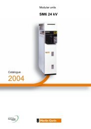
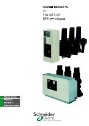
Field of application0The <strong>RM6</strong> can be adapted to meet allmedium voltage power distribution needs,up to <strong>24</strong> <strong>kV</strong>.The <strong>RM6</strong> is a compact unit combining all MV functional unitsto enable connection, supply and protection of one or twotransformers on an open ring or radial networkb by a fuse-switch combination, up to 2000 <strong>kV</strong>Ab by a circuit breaker with self-powered protection unit, up to 3000 <strong>kV</strong>AThe switchgear and busbars are enclosed in a gas-tight chamber, filled with SF6and sealed for life.MT55148MT55147MT55146DE57011EN2
Innovations0A 630 A circuit breaker, to reinforcethe power supply safety of your linesOne of the means by which a power distributor can improve service quality in thenetwork and lower installation costs, is to set up a two-level structure with a main ringdistributing power to secondary rings connected to MV/LV transformers.The <strong>RM6</strong> range 630 A circuit breaker has been designed to provide the protectionfor this intermediate level.With its independent protection sequence, it detects a cable fault (either phase tophase or zero sequence) and instantly isolates it.The VIP 300 protection relay, which is in complete conformity with IEC 60255recommendations, offers a complete range of protection curves in order to adapt todifferent discrimination needs with the main protection upstream.With this ring protection circuit breakerb You benefit from our experience in independent protection systems and lowpressure breaking technologies.b You are provided with switchgear which, motorized either as a factory-built featureor as an on-site upgrade option without interrupting service, is designed to integrateperfectly into the telecontrol of up-to-date distribution networks.055411055410A range that is extensible on siteWhen harsh climatic conditions or environmental restrictions make it necessaryto use compact switchgear, but the foreseeable evolution of the power distributionnetwork makes it necessary to provide for future changes, <strong>RM6</strong> offers a rangeof extensible switchgear.The addition of one or more functional units can be carried out by simply addingstand-alone modules that are connected to each other at busbar level by directedfield bushings.This very simple operation can be carried out on-site:b without handling any gas,b without any special tooling,b without any particular preparation of the floor.The only technical limitation to the evolution of an extensible <strong>RM6</strong>switchboard is therefore the rated current acceptable by the busbar:630 A at 40°C.5
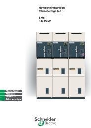
Main characteristics0054603Description of <strong>RM6</strong> switchgear<strong>RM6</strong> switchgear comprises 1 to 4 integrated, low dimension functional units.This self-contained, totally insulated unit comprises:b a stainless steel, gas-tight metal enclosure, sealed for life, which groups togetherthe live parts, switch-disconnector, earthing switch, fuse switch or the circuit breaker,b one to four cable compartments with interfaces for connection to the network or tothe transformer,b a low voltage cabinet,b an electrical operating mechanism cabinet,b a fuse chamber compartment for fused switch-disconnectors or fuse switches.The performance characteristics obtained by the <strong>RM6</strong> meet the definitionof a “sealed pressure system” laid down in the IEC recommendations.The switch-disconnector and the earthing switch offer the operator all necessaryusage guarantees:TightnessThe enclosure is filled with SF6 at a 0.2 bar gauge pressure. It is sealed for life afterfilling. Its tightness, which is systematically checked at the factory, gives theswitchgear an expected lifetime of 30 years. No maintenance of live parts isnecessary with the <strong>RM6</strong> breaking.Switch disconnector<strong>Electric</strong>al arc extinction is obtained using the SF6 puffer technique.Circuit breaker<strong>Electric</strong>al arc extinction is obtained using the rotating arc technique plus SF6auto-expansion, allowing breaking of all currents up to the short-circuit current.Networkswitch-disconnectorIMT55000Selection of functionsTransformer feederfuse-switch combination QTransformer feeder200 A circuit breaker D200 AMT55001MT55002The range offers the user a selection of non extensible <strong>RM6</strong> combinationswith 1, 2, 3 and 4 functional units.Adaptable to all requirements, this makes it possible to choose the transformerfeeder protection:b switch-disconnector combined with fuses,b or 200 A circuit breaker.It also allows the protection of secondary MV rings using 630 A circuit breakers.Line feeder 630 Acircuit breakerB630 AMT55003Most of this switchgear exists in versions that are extensible on the right (type RE)or on both sides (type DE), in order to provide for future development of the network.DE57013Designation of different switchgearType of tankNE: non extensibleRE: extensible on the rightDE: module that is extensibleon the right or the left(1 function)Function configurationI I I IQQDDBBExample of designation<strong>RM6</strong> NE-IQI<strong>RM6</strong> RE-DIDI<strong>RM6</strong> DE-I6
Description of the range0Transformer protectionby fuse-switch combinationsNon-extensible switchgearDE57014NE-QI NE-IQI NE-IIQI NE-QIQIExtensible switchgearDE57015RE-IQI RE-IIQI RE-QIQI DE-I DE-QTransformer protectionby 200 A circuit breakerNon-extensible switchgearDE57016NE-D NE-DI NE-IDI NE-IIDI NE-DIDIExtensible switchgearDE57017RE-IDI RE-IIDI RE-DIDI DE-I DE-D8
Description of the range0Network pointswith switch disconnectorNon-extensible switchgearDE57018NE-I NE-II NE-III NE-IIIIExtensible switchgearDE57019RE-III RE-IIII DE-INetwork pointswith 630 A circuit breakerNon-extensible switchgearDE57020NE-IBI NE-IIBI NE-BIBI NE-B NE-BIExtensible switchgearDE57017RE-IBI RE-IIBI RE-BIBI DE-I DE-B9
Description of theswitchgearSafety of people055750SwitchgearSwitch-disconnectors and circuit breakers have similar architecture:b a moving contact assembly with 3 stable positions (closed, open and earthed)moves vertically (see sketch). Its design makes simultaneous closing of the switchor circuit breaker and the earthing switch impossible,b the earthing switch has a short-circuit making capacity, as required by thestandards,b the <strong>RM6</strong> combines both the isolating and interrupting functions,b the earth collector has the correct dimensions for the network,b access to the cable compartment can be interlocked with the earthing switch and/or the switch or circuit breaker.3 stable position switchMT55161055746Reliable operating mechanismsThe electrical and mechanical operating mechanisms are located behind a frontplate displaying the mimic diagram of the switchgear status (closed, open, earthed):b closing: the moving contact assembly is manipulated by means of a fast-actingoperating mechanism. Outside these manipulations, no energy is stored.For the circuit breaker and the fuse-switch combination, the opening mechanismis charged in the same movement as the closing of the contacts.b opening: opening of the switch is carried out using the same fast-actingmechanism, manipulated in the opposite direction.For the circuit breaker and fuse-switch combination, opening is actuated by:v a pushbutton,v a fault.b earthing: a specific operating shaft closes and opens the earthing contacts.The hole providing access to the shaft is blocked by a cover which can be openedif the switch or circuit breaker is open, and remains locked when it is closed.b switchgear status indicators: are placed directly on the moving contactassembly operating shafts. They give a definite indication of the positionof the switchgear (attachment A of IEC standard 62271-102).b operating lever: this is designed with an anti-reflex device which preventsany attempt to immediately reopen the switch-disconnector or the earthing switchafter closing.b padlocking facilities: 1 to 3 padlocks can be used to prevent:v access to the switch or circuit breaker operating shaft,v access to the earthing switch operating shaft,v operation of the opening pushbutton.Earthing displayb earthing switch closed position indicators: these are located on the upper partof the <strong>RM6</strong>. They can be seen through the transparent earthing covers, when theearthing switch is closed.055752Internal arc withstandThe robust, reliable and environmentally insensitive design of the <strong>RM6</strong> makes ithighly improbable that a fault will appear inside the switchgear.Nevertheless, in order to ensure maximum personal safety, the <strong>RM6</strong> is designed towithstand an internal arc supplied by a rated short-circuit current for 1 second,without any danger to the operator.Accidental overpressure due to an internal arc is limited by the opening of the safetyvalve, at the bottom of the metal enclosure.The gas is released to the rear of the <strong>RM6</strong> without affecting conditions in the front.After standard testing carried out for 20 kA, 1 s, the device meets the six criteriadefined by appendix AA of IEC 60298.10
Description of theswitchgear0Insensitivity to the environment055749Complete insulationb A metal enclosure made of stainless steel, which is unpainted and gas-tight(IP67), contains the live parts of the switchgear and the busbars;b Three sealed fuse chambers, which are disconnectable and metallizedon the outside, insulate the fuses from dust, humidity...b Metallization of the fuse chambers and directed field terminal connectorsconfines the electrical field in the solid insulation.Taken together, the above elements provide the <strong>RM6</strong> with genuine total insulationwhich makes the switchgear completely insensitive to environmental conditions,dust, extreme humidity, temporary soaking.(IP67: immersion for 30 minutes, as laid down in IEC standard 60529, § 14.2.7).055757Operating safetyCable insulation testIn order to test cable insulation or look for faults, it is possible to inject a directcurrent of up to 42 <strong>kV</strong>dc for 15 minutes through the cables via the <strong>RM6</strong>, withoutdisconnecting the connecting devices.The earthing switch is closed and the moving earthing connection is openedin order to inject the voltage via the “earthing covers”. This system, a built-in featureof the <strong>RM6</strong>, requires the use of injection fingers (supplied as an option).MT55162Voltage indicator lampsA device (supplied as an option) on all functional units makes it possible to checkthe presence (or absence) of voltage in the cables.Two types of indicator can be proposed according to network operating habits:b A device with built-lamps, of the VPIS type (Voltage Presence Indicating System)complying with standard IEC 61958.055809b or a system with separate luminous modules, of the VDS type (Voltage DetectionSystem) complying with standard IEC 61<strong>24</strong>3-5.11
Transformer protection Using fuse switches 0MT550<strong>24</strong>Fuse dimensionsSolefuse (UTE)35 450 35 23Fusarc CF (DIN)Ratings for fuses for transformer protection depend, among other points,on the following criteria:b service voltage,b transformer rating,b thermal dissipation of the fuses,b fuse technology.Two types of fuse may be installed:b Solefuse type: according to UTE NFC 64210 standard, with or without striker,b Fusarc CF type: according to DIN 62271-105 dimensional standard, with orwithout striker.Example (using the selection table below) general case, for protection of a 400 <strong>kV</strong>Atransformer at 10 <strong>kV</strong>, either Solefuse fuses with a rating of 63 A or Fusarc CF fuseswith a rating of 50 A are chosen.33 L 33 23For fuses of other manufacturers, please consult us.Rated Rating L Ø Massvoltage (<strong>kV</strong>) (A) (mm) (mm) (kg)12 10 to 20 292 50.5 1.225 to 40 292 57 1.550 to 100 292 78.5 2.8<strong>24</strong> 10 to 20 442 50.5 1.625 to 40 442 57 2.250 to 63 442 78.5 4.180 to 100 442 86 5.3Fuse replacementIEC and UTE recommendations stipulate that when a fuse has blown, all threefuses must be replaced.Selection table(Rating in A, no overload, –25°C < θ < 40°C)Fuse Operating Transformer rating (<strong>kV</strong>A) Ratedtype voltage(<strong>kV</strong>)50 75 100 125 160 200 250 315 400 500 630 800 1000 1250 1600 2000 voltage(<strong>kV</strong>)UTE NFC standards: 13100, 64210Solefuse5.5 16 31.5 31.5 63 63 63 63 63 7.210 16 16 31.5 31.5 31.5 63 63 63 63 <strong>24</strong>15 16 16 16 16 16 43 43 43 43 43 6320 16 16 16 16 16 16 43 43 43 43 43 63General case, IEC 60282-1 standard, IEC 62271-105 (to replace IEC 60420) and DIN 43265 standardFusarc CF3 20 31.5 40 50 50 63 80 100 125 160* 123.3 20 25 40 40 40 63 80 80 125 125 160*4.2 20 25 25 40 50 50 63 80 80 100 125 160*5.5 16 20 25 25 40 40 50 63 80 80 100 125 160*6 16 20 25 25 31.5 40 50 50 63 80 100 125 160*6.6 10 20 25 25 31.5 40 50 50 63 63 80 100 125 160*10 10 10 16 20 25 25 31.5 40 50 50 63 80 100 12511 10 10 16 20 20 25 25 40 40 50 50 63 80 100 12513.8 10 10 10 16 16 20 25 31.5 40 40 50 50 63 100 <strong>24</strong>15 10 10 10 10 16 20 25 31.5 31.5 40 50 50 63 80 10020 10 10 10 10 16 16 20 25 25 31.5 40 40 63 63 80 10022 10 10 10 10 10 16 16 20 25 31.5 40 40 50 63 80 100(*) please consult us.For all fuse ratings not included in the table, please consult us.Please consult us for overloads or operation over 40°C.12
Transformer protection Using a 200 A circuit breaker 0054475DE57022VIP 30 VIP 35s1001010,1total breaking time054476In contrast to fuses, the circuit breaker has no minimum breaking current,which means that it is particularly well-adapted to transformer protection.Protection systemThe protection system operates without an auxiliary power supply, and includes:b 3 transformers with integrated toroids on the transformer feeder bushings,b 1 VIP 30 or VIP 35 electronic relay,b 1 release,b 1 test connector to check whether the protection unit is operating correctly,using the VAP 6 unit.VIP 30 and VIP 35 self-powered protection relaysVIP 30 and VIP 35 are self-powered relays, requiring no auxiliary power supply,which are fed by current sensors, activating a MITOP release.VIP 30 protects against phase to phase faults.VIP 35 protects against phase to phase faults and earth faults.Descriptionb the relays are assembled in a housing, and the front faces are protecteda transparent cover. The whole assembly has a degree of protection of IP54,b settings are made on the front, using rotary switches,b the phase operating current is adjusted directly according to the transformer ratingand the operating voltage,b the earth current set point is adjusted according to the network characteristics.Phase protectionb phase protection is provided by an IDMT set point which operates as of 1.2 timesthe operating current (Is). VIP 30 and VIP 35 phase protections are identical.Earth protectionb earth fault protection operates with measurement of the residual current carriedout using the sum of the secondary currents of the sensors,b earth protection operates in definite time: both its set point and time delayare adjustable.type0,010 1,251015202530I/IsThe curve represent the relay intervention time, to which 70 msmust be added to obtain the breaking time.Rated protection current setting selectionOperating Transformer rating (<strong>kV</strong>A)Ratedvoltage(<strong>kV</strong>)50 75 100 125 160 200 250 315 400 500 630 800 1000 1250 1600 2000 2500 3000 voltage(<strong>kV</strong>)3 10 15 20 25 36 45 55 68 80 140 140 170 200 123.3 10 15 18 22 28 36 45 56 70 90 140 140 2004.2 8 12 15 18 22 28 36 45 56 70 90 140 140 2005.5 8 12 15 18 22 28 36 46 55 68 90 140 140 2006 10 12 18 20 25 36 46 55 68 80 140 140 200 2006.6 10 12 15 18 22 28 36 45 56 70 90 140 140 20010 8 10 12 15 20 25 30 37 55 68 80 140 140 170 20011 10 12 15 18 22 28 36 45 55 68 90 140 140 17013.8 8 10 12 15 18 22 28 36 46 55 68 90 140 140 <strong>24</strong>15 8 10 15 18 20 25 36 45 55 68 80 140 14020 8 10 15 20 25 30 37 45 55 68 80 14022 8 10 12 15 18 22 28 36 45 55 68 8013
Line protection Using a 630 A circuit breaker 0054477The 630 A circuit breaker has been designed to protect medium voltage feeders asnear to the fault as possible. The protection unit is identical to that of the 200 A circuitbreaker, with a VIP 300 relay adapted to network protection.VIP 300 self-powered protection relayb VIP 300 protects against phase to phase faults and earth faults. The choice oftripping curves, and the multiplicity of settings enable it to be used with a wide varietyof discrimination plans.b VIP 300 is a self-powered relay which obtains its power supply from currentsensors. It does not need an auxiliary power supply. It actuates a release.VIP 300DescriptionThe operating principle of the protection unit is the same as for the VIP 300and VIP 35 relays.Phase protectionb Phase protection has two independently adjustable set points:v either an IDMT or definite low set point can be selected. The IDMT curvesare in conformity with the IEC 60255-3 standard. They are of the inverse,very inverse and extremely inverse type,v the high set point is a definite time one.Earth protectionb Earth fault protection operates with measurement of the residual current carriedout using the sum of the secondary currents of the sensors.b As with phase protection, earth protection has two independently adjustable setpoints.Indicationb Two indicators show the origin of tripping (phase or earth). They remain in positionafter the relay power supply is cut off.b Two LED indicators (phase and earth) indicate that the low set point has beenexceeded and its time delay is in progress.DE57023DE570<strong>24</strong>t >t >t >>t >>Is 1.2 Is 10 Is I >>With IDMT low set pointIs I >I >>With definite time low set point14
Line protection IDMT tripping curves 0b The curves in this chapter indicate the low set IDMT tripping times for time delaysettings t > (or to >).b The phase protection and earth protection curves are identical.DE55728100t (s)100t (s)101010.164321.510.60.40.30.20.150.10.070.0510.164321.510.60.40.30.20.150.10.070.050.011RI curve10100I/Is0.011 1.2SI curve10100I/IsDE557291000t (s)1000t (s)100100101010.10.011 1.21064321.510.60.40.30.20.150.10.070.05100I/Is10.10.011 1.21064321.510.60.40.30.20.150.10.070.05100I/IsVI curveEI curve15
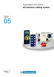
Telecontrol of powerdistribution networks0Continuity of service guaranteedby an overall telecontrol offer<strong>Schneider</strong> <strong>Electric</strong> offers you a complete solution, including:b the Easergy T200 telecontrol interface,b MV switchgear that is adapted for telecontrol.DE57026ENHV/MVEasergy T200Easergy T200<strong>RM6</strong> IIII <strong>RM6</strong> IDI <strong>RM6</strong> IIIINetwork control centreCommunication networkMV ring<strong>RM6</strong> IDIEasergy T200<strong>RM6</strong> IIII<strong>RM6</strong> IDIPosition of the <strong>RM6</strong><strong>RM6</strong> switchgear is perfectly adapted to the telecontrol context,thanks to options such as:b Easergy T200 telecontrol interface,b electrical rating mechanism,b auxiliary fault and position indication contacts,b current sensors for fault detection.16
Telecontrol of powerdistribution networks061015NEasergy T200: an interface designedfor telecontrol of MV networksEasergy T200 is a “plug and play” or multifunction interface that integratesall the functional units necessary for remote supervision and control of the <strong>RM6</strong>:b acquisition of the different types of information: switch position, fault detectors,current values...b transmission of switch open/close orders,b exchanges with the control center.Required particularly during outages in the network, Easergy T200 is of provenreliability and availability, being able to ensure switchgear operation at any moment.It is simple to set up and to operate.61019N61017NFunctional unit designed for the Medium Voltage networkb Easergy T200 is designed to be connected directly to the MV switchgear,without requiring a special converter.b It has a simple front plate for local operation, which allows management ofelectrical rating mechanisms (local/remote switch) and display of informationconcerning switchgear status.b It has an integrated MV network fault current detection system (overcurrent andzero sequence) with detection set points that can be configured channel by channel(current value and fault current duration).Local informationsMonitoring and control61020NPower supply61018NPolarized connectorsMedium Voltage switchgear operating guaranteeb Easergy T200 has undergone severe MV electrical stress withstand tests.b It is a backed up power supply which guarantees continuity of service for severalhours in case of loss of the auxiliary source, and supplies power to the Easergy T200and the MV switchgear motor mechanisms.b Ready to plugb Easergy T200 is delivered with a kit that makes it easy to connect the motormechanisms and collect measurements.b The telecontrol cabinet connectors are polarized to avoid any errors duringinstallation or maintenance interventions.b Current measurement acquisition sensors are of the split type, to facilitatetheir installation.61021NSplit sensors17
Accessories(supplied as an option)Remote control 0Motor mechanism055748Switch operating mechanismb The switch operating mechanism includes a space that is reserved for theinstallation of a geared motor. This can be installed at the factory, but it can alsothe installed on-site, by the customer, without de-energizing the unit, and withoutdismantling the operating mechanism.b An electrical interlocking assembly prohibits any false operations.Once motorized, the <strong>RM6</strong> integrates perfectly into a telecontrol system.055807Circuit breaker operating mechanismb Circuit breaker protection functional units can be equipped with a geared motor.This can be installed at the factory, but it can also be installed on-site, by the customer,without de-energizing the unit, and without dismantling the operating mechanism.b <strong>Electric</strong>al locking prohibits any false operations, with, as an option, closing afteran unacknowledged fault. Once motorized, the <strong>RM6</strong> integrates perfectly intoa telecontrol system.This option becomes particularly useful in the context of the protectionof a secondary ring, with supervision by a telecontrol system.055748bAuxiliary contactsEach switch or circuit breaker can be fitted with 4 auxiliary contacts with the followingpositions: 2 NO and 2 NC.Each earthing switch can be fitted with 1 auxiliary contact with the following position:(opening/closing).Each circuit breaker can be fitted with 1 fault indication auxiliary contact.Each fuse-switch combination can be fitted with 1 blown fuse indication auxiliarycontact.055747Opening releaseEach circuit breaker or fuse-switch combination can be fitted a switch-on openingrelease (shunt trip).18
Accessories(supplied as an option)Fault current indication 0PE15086<strong>RM6</strong> switchboard integrate fault passage indicators, on every switch function:Flair 21D, Flair 21DT, Flair 22D (*).These FPI arc self-powered by the sensors and comprise a digital display.They provide:b earth fault indication,b phase fault indication,b load current display (Ampermeter).(*) <strong>RM6</strong> can also be provided with Alpha M or Alpha E (Hortzmann) type short circuit indicators.Flair 21D and 21DTPE15087Flair 22DDE57025ENConnection 21D 21DT 22DL3L2L1Fault detectionEarth fault 20 to 160 A 20 to 160 A 20 to 160 APhase fault20 to 160 AReset b b bSCADA interface b b21DSCADAL3L2L1ResetVisualisationDisplay 2 digits 2 digits 4 digitsLoad current 10 A 10 A 1 AAccuracy 10% 10% 10%Settings b b bFaulty phase b b bFrequencybPeak demand currentbLoad current demandb21DTSCADAL3L2L1ResetOthersDual-powered (sensor and battery)bExternal light b b b22DFlair 21D et Flair 21DT operate with a load current more than 3 A.Due to a lithium battery, Flair 22D operates with no load current(setting display, reset temporisation > 4 h)19
Accessories(supplied as an option)0Installation, maintenance045780Phase concordance unitThis unit is used to check phase concordance.It can be connected to any voltage indicator lamp device.055814Protection relay testb The portable VAP 6 unit is connected to the circuit breaker protection relay:v injecting an electrical stimulus, two pushbuttons are used to check that theshort-circuit and zero sequence fault current protection devices are operating,v an extra pushbutton may be provided to inhibit tripping of the circuit breaker.Local signalisation055809bVoltage indicator lampThere is a voltage indicator device on network switches, circuit breakers andfuse-switch combinations, which makes it possible to check whether or not there isa voltage across the cables.Two devices are offered:b VDS: Voltage Detecting System,b VPIS: Voltage Presence Indication System.20
Accessories(supplied as an option)Key locks 0The markings (O, S, and X) are engraved on the keys and the locks.They are given here only as an aid to understanding of the diagrams.MT55154Type R1 diagramMT55040OOn network switches or 630 A circuit breakerfeederOSemi-crossed lockingb Prohibits the closing of the earthing switch of the downstream switchgear unlessthe upstream switchgear is locked in the “open” position.Type R2 diagramMT55041OXCrossed lockingb Prohibits closing of the earthing switches unless the upstream and downstreamswitchgear is locked in the “open” position.XOType R7 diagramMT55042On transformer feeders<strong>RM6</strong> / transformerb Prohibits access to the transformer unless the earthing switch has been locked inthe “closed” position.SSType R6 diagramMT55043O<strong>RM6</strong> / low voltageb Prohibits closing of the earthing switch and access to any protection unit fusesunless the main LV circuit breaker has been locked in the “open” or “disconnected”position.OType R8 diagramMT55044O<strong>RM6</strong> / transformer / low voltageb Prohibits closing of the earthing switch and access to any protection unit fusesunless the main LV circuit breaker has been locked in the “open” or “disconnected”position.b Prohibits access to the transformer unless the earthing switch has already been“closed”.SOSLegend:absent keyMT55045free keycaptive key21
Selection of connections0MT55039Generalb The profiles, contacts and dimensions of the <strong>RM6</strong> connection interfaces are definedby the IEC 60137 standard.b 100% of the epoxy resin interfaces undergo dielectric testing at power frequencyand partial discharge tests.type ATypes of connection interfacetype B / CAppropriateness for useThe bushings carry the electrical current from the outside to the insideof the enclosure, which is filled with SF6 gas, ensuring insulation betweenthe live conductors and the frame.There are 3 types of bushing, which are defined by their short-time withstandcurrent:type A: 200 A: 12.5 kA 1 s and 31.5 kA peak (plug-in)type B: 400 A: 16 kA 1 s and 40 kA peak (plug-in)type C: 630 A: 25 kA 1 s and 62.5 kA peak (disconnectable M16).This information must be specified for betterdefinition of the connection interfaces.How to define the connection interfaceThe connection interfaces depend on specific criteria, such as:Installationb Current rating of the connected equipment: 200, 400, 630 Ab Short-time withstand current for 12.5 kA, 16 kA, 25 kA switch and circuit breakerfunctionsb For the fuse-switch combination function, as the short-circuit current is limitedby the fuse, the connection interface will be of type A (200 A)b Minimum phase expansion lengthb Connection type:v plug in: multicontact ring,v disconnectable: bolted.b Output position: straight, elbow.Cableb Specified voltage:v of the cable,v of the network.b Type of conductor:v aluminium,v copper.b Cross section in mm 2b Insulation diameterb Cable composition:v single-core,v 3-core.b Insulation type:v dry,v paper impregnated (non-draining type).b Type of screenb Armature.054600Standard cable compartment equipmentb A closing panel,b Cable binding,b Cable grounding connections.Options:v panel with hood for display of liquid type overcurrent indicators installed aroundthe cables,v panel for connectors with lightning arrestor,v interlocking which prohibits access to the connection compartmentwhen the earthing switch is open,v interlocking which prohibits closing of the switch or circuit breakerwhen the connection compartment panel is open,v back of compartment for single-core or 3-core cables (mandatory for non-directedfield connections),v cable compartment internal arc withstand up to 16 kA 1s.22
Selection of connections 0Prefered connection for <strong>RM6</strong>For network switch-disconnectorsDry single-core cableType B bushing - 400 A - limited to 16 kA/sDirected field plug-in connectorPerformance Connection Supplier Reference Cross section Remarks7.2 to 17.5 <strong>kV</strong> Plug-in nkt cables GmbH CE 12-400 25 to 300400 A-95 <strong>kV</strong> impulse<strong>24</strong> <strong>kV</strong> Plug-in nkt cables GmbH CE <strong>24</strong>- 400 25 to 300400 A-125 <strong>kV</strong> impulseFor network switch-disconnectorsand line protection circuit breakersDry single-core cableType C bushing - 630 ADirected field disconnectable connectorPerformance Connection Supplier Reference Cross section Remarks7.2 to 17.5 <strong>kV</strong> Disconnectable nkt cables GmbH CB 12-630 25 to 300630 A-95 <strong>kV</strong> impulse<strong>24</strong> <strong>kV</strong> Disconnectable nkt cables GmbH CB <strong>24</strong>- 630 25 to 300630 A-125 <strong>kV</strong> impulseDry single and 3 core cableType C bushing - 630 ANon-directed field disconnectable connectorPerformance Connection Supplier Reference Cross section Remarks7.2 to 17.5 <strong>kV</strong> Disconnectable nkt cables GmbH AB 12-630 25 to 300 For 3-core cable630 A-95 <strong>kV</strong> impulse (+ ATS)<strong>24</strong> <strong>kV</strong> Disconnectable nkt cables GmbH AB <strong>24</strong>- 630 25 to 300 For 3-core cable630 A-125 <strong>kV</strong> impulse (+ ATS)For network switch-disconnectorsand line protection circuit breakersSingle-core cable and lightning arresterType C bushing - 630 ADisconnectable connectorPerformance Connection Supplier Reference Cross section Remarks7.2 to 17.5 <strong>kV</strong> Disconnectable nkt cables GmbH AB 12-630 + 25 to 300 Non-directed field630 A-95 <strong>kV</strong> impulse ASA12(5 or 10 kA)CB <strong>24</strong>- 630 + 25 to 300 Directed fieldCSA <strong>24</strong>(5 or 10 kA)<strong>24</strong> <strong>kV</strong> Disconnectable nkt cables GmbH AB 12-630 + 25 to 300 Non-directed field630 A-125 <strong>kV</strong> impulse ASA12(5 or 10 kA)CB <strong>24</strong>- 630 + 25 to 300 Directed fieldCSA <strong>24</strong>(5 or 10 kA)23
Selection of connections0For transformer protection by circuit breakersDry single core cableType A bushing - limited to 12.5 kADirected field plug-in connectorPerformance Connection Supplier Reference Cross section Remarks7.2 to 17.5 <strong>kV</strong> Plug-in nkt cables GmbH EASW 12/250 A 25 to 95 Shaped elbow200 A-95 <strong>kV</strong> impulse Plug-in nkt cables GmbH EASG 12/250 A 25 to 95 Straight<strong>24</strong> <strong>kV</strong> Plug-in nkt cables GmbH EASW 20/250 A 25 to 95 Shaped elbow200 A-125 <strong>kV</strong> impulse Plug-in nkt cables GmbH EASG 20/250 A 25 to 95 StraightDry single core cableType B bushing - limited to 16 kADirected field plug-in connectorPerformance Connection Supplier Reference Cross section Remarks7.2 to 17.5 <strong>kV</strong> Plug-in nkt cables GmbH CE 12-400 A 25 to 300200 A-95 <strong>kV</strong> impulse<strong>24</strong> <strong>kV</strong> Plug-in nkt cables GmbH CE <strong>24</strong>-400 A 25 to 300200 A-125 <strong>kV</strong> impulseDry single core cableType C bushing - Isc 21 kA/1 sDirected field disconnectable connectorPerformance Connection Supplier Reference Cross section Remarks7.2 to 17.5 <strong>kV</strong> Disconnectable nkt cables GmbH CB 12-630 A 25 to 300Dry single and 3 core cableType C bushing - Isc 21 kA/1 sNon-directed field disconnectable connectorPerformance Connection Supplier Reference Cross section Remarks7.2 to 17.5 <strong>kV</strong> Disconnectable nkt cables GmbH AB 12-630 A 25 to 300200 A-95 <strong>kV</strong> impulseFor transformer protection by fuse-switchcombinationDry single core cableType A bushing - limited to 12.5 kADirected field plug-in connectorPerformance Connection Supplier Reference Cross section Remarks7.2 to 17.5 <strong>kV</strong> Plug-in nkt cables GmbH EASW 12/250 A 25 to 95 Shaped elbow200 A-95 <strong>kV</strong> impulse Plug-in nkt cables GmbH EASG 12/250 A 25 to 95 Straight<strong>24</strong> <strong>kV</strong> Plug-in nkt cables GmbH EASW 20/250 A 25 to 95 Shaped elbow200 A-125 <strong>kV</strong> impulse Plug-in nkt cables GmbH EASG 20/250 A 25 to 95 Straight<strong>24</strong>
Selection of connections 0The following connections arealso compatible with the <strong>RM6</strong>For network switch-disconnectorsDry single-core cableType B bushing - 400 A - limited to 16 kA/1 sDirected field plug-in connectorPerformance Connection Supplier Reference Cross section Remarks7.2 to 10 <strong>kV</strong> Plug-in Elastimold 400 LR 70 to <strong>24</strong>0 Limited to Us = 10 <strong>kV</strong>400 A-95 <strong>kV</strong> impulse<strong>24</strong> <strong>kV</strong> Plug-in Pirelli FMCE 400 70 to 300400 A-125 <strong>kV</strong> impulse Elastimold K400LR 35 to <strong>24</strong>0Pirelli FMCE 400 70 to 300Kabeldon SOC 630 50 to 300For network switch-disconnectorsand line protection circuit breakersDry single-core cableType C bushing - 630 ADirected field disconnectable connectorPerformance Connection Supplier Reference Cross section Remarks7.2 to 10 <strong>kV</strong> Disconnectable Elastimold 440 TB 70 to <strong>24</strong>0630 A-95 <strong>kV</strong> impulse7.2 to <strong>24</strong> <strong>kV</strong> Disconnectable Pirelli FMCTs 400 70 to 300630 A-125 <strong>kV</strong> impulse Elastimold K400TB 35 to <strong>24</strong>0Kabeldon SOC 630 50 to 300Dry single and 3 core cableType C bushing - 630 ANon-directed field disconnectable connectorPerformance Connection Supplier Reference Cross section Remarks7.2 to 17.5 <strong>kV</strong> Heat shrinkable Raychem EPKT+EAKT 16 to 300630 A-95 <strong>kV</strong> impulse Sigmaform Q-CAP 16 to 300Insulating boots Kabeldon SOC 630 50 to 300 Completed by a kitfor three-pole cablePirelli ELPB12 50 to 300 Limited to 75 <strong>kV</strong> impulseSimplified disconnectable Raychem RICS - EPKT 25 to 300Euromold 15TS-NSS 50 to 300 Limited to Us = 12 <strong>kV</strong><strong>24</strong> <strong>kV</strong> Simplified disconnectable Raychem RICS - EPKT 25 to 300630 A-125 <strong>kV</strong> impulse25
Selections of connections0For network switch-disconnectorsand line protection circuit breakersSingle core cable, paper impregnated, non draining typeType C bushing - 630 ANon-directed field disconnectable connectorPerformance Connection Supplier Reference Cross section Remarks7.2 to 17.5 <strong>kV</strong> Disconnectable Pirelli FMCp400 95 to 300630 A-95 <strong>kV</strong> impulse Insulating boots Kabeldon SOC 25 to 300Pirelli ELPB12 50 to 300 Limited to 75 <strong>kV</strong> impulseSimplified disconnectable Raychem RICS - EPKT 25 to 300Heat shrinkable Raychem EPKT+EAKT 95 to 300<strong>24</strong> <strong>kV</strong> Disconnectable Pirelli FMCp 1c 95 to 300630 A-125 <strong>kV</strong> impulse Simplified disconnectable Raychem RICS - EPKT 25 to 300Three core cable, paper impregnated, non-draining typeType C bushing - 630 ANon-directed field disconnectable connectorPerformance Connection Supplier Reference Cross section Remarks7.2 to 17.5 <strong>kV</strong> Insulating boots Kabeldon SOC 630 25 to 300630 A-95 <strong>kV</strong> impulse Pirelli ELPB12 50 to 300 Limited to 75 <strong>kV</strong> impulseSimplified disconnectable Raychem RICS - EPKT 25 to 300Heat shrinkable Raychem EPKT+EAKT 16 to 300<strong>24</strong> <strong>kV</strong> Simplified disconnectable Raychem RICS - EPKT 25 to 300630 A-125 <strong>kV</strong> impulseSingle core dry cable and lightning arrerstorType C bushing - 630 ADisconnectable connectorPerformance Connection Supplier Reference Cross section Remarks7.2 to 17.5 <strong>kV</strong> Disconnectable Raychem RICS+EPKT 25 to 300630 A-95 <strong>kV</strong> impulse RDA 12 ou 18Disconnectable Elastimold K400TB+ 35 to 300 Panel with the enlarged <strong>RM6</strong>K400RTPA+K156SA<strong>24</strong> <strong>kV</strong> Disconnectable Raychem RICS+EPKT 25 to 300630 A-125 <strong>kV</strong> impulse RDA <strong>24</strong>Disconnectable Elastimold K440TB+ 35 to 300 Panel with the enlarged <strong>RM6</strong>K400RTPA+K156SA26
Selection of connections0For transformer protection by circuit breakerDry single-core cableType A bushing - limited to 12.5 kADirected field plug-in connectorPerformance Connection Supplier Reference Cross section Remarks7.2 to 10 <strong>kV</strong> Plug-in Elastimold 158LR 16 to 120200 A-95 <strong>kV</strong> impulse<strong>24</strong> <strong>kV</strong> Plug-in Pirelli FMCE 250 16 to 120200 A-125 <strong>kV</strong> impulse Elastimold K158LR 25 to 95Pirelli FMCE 250 16 to 120Dry single-core cableType B bushing - limited to 16 kADirected field plug-in connectorPerformance Connection Supplier Reference Cross section Remarks7.2 to 10 <strong>kV</strong> Plug-in Elastimold 400LR 70 to <strong>24</strong>095 <strong>kV</strong> impulse<strong>24</strong> <strong>kV</strong> Plug-in Elastimold K400LR 35 to <strong>24</strong>0400 A-95 <strong>kV</strong> impulse Pirelli FMCE 400 70 to 300Dry single-core cableType C bushing - Isc 21 kA/1 sDirected field disconnectable connectorPerformance Connection Supplier Reference Cross section Remarks7.2 to 17.5 <strong>kV</strong> Disconnectable Elastimold 440TB 70 to <strong>24</strong>0 Limited to Us = 10 <strong>kV</strong>200 A-95 <strong>kV</strong> impulse K440TB 35 to <strong>24</strong>0Isc > 16 kA Pirelli FMCTs 400 70 to 300Dry single-core and 3 core cableType C bushing - Isc 21 kA/1 sNon-directed field disconnectable connectorPerformance Connection Supplier Reference Cross section Remarks7.2 to 17.5 <strong>kV</strong> Heat shrinkable Raychem EPKT+EAKT 16 to 300200 A-95 <strong>kV</strong> impulse Sigmaform Q-CAP 16 to 300Insulating boots Kabeldon SOC 630 25 to 300Pirelli ELPB12 50 to 300 Limited to 75 <strong>kV</strong> impulseSimplified disconnectable Raychem RICS - EPKT 25 to 300Elastimold SV412C 50 to 300 Limited to Us = 10 <strong>kV</strong>27
Selection of connections0For transformer protection by fuse-switchcombinationSingle-core cableType A bushing - limited to 12.5 kA 1 sDirected field plug-in connectorPerformance Connection Supplier Reference Cross section Remarks7.2 to 10 <strong>kV</strong> Plug-in Elastimold 158LR 16 to 120 T-shaped elbow200 A-95 <strong>kV</strong> impulse 151SR 16 to 120 StraightPirelli FMCE 250 16 to 957.2 to <strong>24</strong> <strong>kV</strong> Plug-in Elastimold K158LR 16 to 95 T-shaped elbow200 A-125 <strong>kV</strong> impulse K151SR 25 to 95 Straight(*) 520 mm plinth must be usedDry single-core and 3 core cableType A profile bushing and M8 insert - 200 ANon-directed field disconnectable connector (*)Performance Connection Supplier Reference Cross section Remarks7.2 to 17.5 <strong>kV</strong> Heat shrinkable Raychem EPKT+EAKT 16 to 150200 A-95 <strong>kV</strong> impulse Insulating boots Kabeldon KAP70 70 max.28
phaseovercurrentI >tripIsresettrip375062Io > 30(A)earth fault Ios22 283646568806812151810(A)minimum operatingphase current : 10 A75 9512015020025300250I >DT onlyVI EISIRIoffDTcurve selection0,15 0,20,1 0,30,07 0,40,05 0,5(s)t >Io >DT onlyVI EISIRIoffDTcurve selection0,15 0,20,1 0,30,07 0,40,05 0,5(s)to >1,8 2,11,5 2,41,2 2,713(x Is)x 10x 11,8 2,11,5 2,41,2 2,713(x Is)x 10x 1I >>9 126 154 203 off(x Ios)0,2 0,40,1 0,60,05 0,90,03 1,5(s)t >>Io >>9 126 154 203 off(x Ios)0,2 0,40,1 0,60,05 0,90,03 1,5(s)to >>VIP 300VAP6 test plugphaseovercurrentI >tripIsresettrip375062Io > 30(A)earth fault Ios22 283646568806812151810(A)minimum operatingphase current : 10 A75 9512015020025300250I >VISIRIDTt >Io >DT onlyVI EISIRIoffDTcurve selection0,15 0,20,1 0,30,07 0,40,05 0,5(s)to >EIcurve selectionoff0,15 0,20,1 0,30,07 0,40,05 0,5(s)DT only1,8 2,11,5 2,41,2 2,713(x Is)x 10x 11,8 2,11,5 2,41,2 2,713(x Is)x 10x 1I >>9 126 154 203 off(x Ios)0,2 0,40,1 0,60,05 0,90,03 1,5(s)t >>Io >>9 126 154 203 off(x Ios)0,2 0,40,1 0,60,05 0,90,03 1,5(s)to >>VIP 300VAP6 test plugDimensionsand installation0Dimensions of non-extensible <strong>RM6</strong>sDE5703011407036927101619 1186<strong>RM6</strong> 4 functional units<strong>RM6</strong> 3 functional units703437829<strong>RM6</strong> 2 functional units572 572<strong>RM6</strong> 1 functional unitswitch<strong>RM6</strong> 1 functional unitcircuit breakerDimensions of 3 and 4 function <strong>RM6</strong> REsthat are extensible on the rightDE5703111407036927101649 1216<strong>RM6</strong> 4 functional units<strong>RM6</strong> 3 functional unitsDimensions of stand-alone <strong>RM6</strong> modulesthat are extensible on both sidesWith two bushing protection covers for extensibility.DE57032<strong>RM6</strong> 1 functionalunit switch orfuse-switchcombination<strong>RM6</strong> 1 functionalunit circuit breaker532 63229
Dimensionsand installation0Dimensions of <strong>RM6</strong> REs with an extensionmoduleDE57033703670710A43Layout1140900 (*)(*) dimensions necessaryon the right of the <strong>RM6</strong>in order to installan extensionb <strong>RM6</strong> RE 3 functional unitswith switch DE module:A = 1738 mmb <strong>RM6</strong> RE 4 functional unitswith switch DE module:A = 2171 mmb <strong>RM6</strong> RE 3 functional unitswith circuit breaker DE module:A = 1838 mmb <strong>RM6</strong> RE 4 functional unitswith circuit breaker DE module:A = 2271 mmFloor mountingThe <strong>RM6</strong> is supported by 2 metal feet with holes for mounting:b on a flat floor fitted with trenches, passages or ducts,b on concrete footings,b on studs,b on metal rails,b etc.Non-extensible <strong>RM6</strong>DE570341690125790064364564510,215631130<strong>RM6</strong> 4 functional units <strong>RM6</strong> 3 functional units <strong>RM6</strong> 2 functionalunits<strong>RM6</strong> 1 functionalunitExtensible <strong>RM6</strong>F43<strong>RM6</strong> 3 functional unitsF = 1779 mmwith switchG = 1652 mm<strong>RM6</strong> 3 functional units with combined switchF = 1879 mmor circuit breakerG = 1752 mm64510,2<strong>RM6</strong> 4 functional unitsF = 2212 mmwith switchG = 2085 mmG<strong>RM6</strong> 4 functional units with combined switchF = 2312 mm<strong>RM6</strong> 3 or 4 functional units with extensibilitymoduleor circuit breakerG = 2185 mm773516DE570351023123868 minimumWall mountingThere are two holes allowing the unit to be fixed on the wall as well as mountedon the floor.Additional raising plinthAs an option, the <strong>RM6</strong> can be fitted with a 260 or 520 mm raising plinth.This addition, which simplifies civil engineering works, results in trenchesof a smaller depth, or even in their complete elimination when the bending radiusof the cables allows it.The plinth is mounted directly on the floor.30
Civil engineering0For connection to “network”or “transformer”via circuit breakerThe “network” cables can be run either:b through trenches, passages, ducts,b through the left or the right side.DE57027Cable entry through a trenchCable entry through a duct325 325Trench depth P for <strong>RM6</strong> without plinthNote: trench depths can be reduced and sometimeseliminated by adding a plinth.Cable Cable Cross-section Bending Plug-in Disconnectable Plug-in Disconnectableinsulation (mm 2 ) radius P P P PDry insulation Single ≤ 150 500 400 400185 to 300 600 520 520Three ≤ 150 550 660 660185 650 770 770Paper Single ≤ 150 500 580 580impregnatedDraining 185 to 300 675 800 800Type Three ≤ 95 635 750 750150 to 300 835 970 970For “transformer”connection via fuse-switchThe cross-sections of “transformer” cables are generallysmaller than those of the “network” cables.All the cables are then run through the same space.When straight MV connectors are used, the depth Pindicated below can be greater than that of the“network” cables.DE57028(1)Cable Cable Cross-section Bending Plug-in Plug-in Disconnectable (2)insulation (mm 2 ) radius elbow connector straight connector PDry insulation Single 16 to 35 335 100 520 33550 to 70 400 100 520 44095 to 120 440 100 550 440Three 35 435 100 520 72550 to 70 500 100 520 80095 545 100 550 860(1) leave a clearance of 100 mm(2) 520 mm plinth must be used31
A leader’s references <strong>RM6</strong>, a world-wide product 0NorwaySwedenMT55158MT55160DE57036MT55156MT55157SpainMT55159AustraliaRussiaMain referencesAsia / Middle Eastb BSED, Bahreinb DEWA, Dubaïb WED, Abu Dhabib Tianjin Taifeng Industrial Park, Chinab TNB, Malaysiab China Steel Corporation, Taiwanb TPC, Taiwanb SCECO, Saudi ArabiaAfricab <strong>Electric</strong>ité de Mayotteb EDF Reunionb Total, Libyab SONEL, CameroonSouth America / Pacificb CELESC, Santa Catarina, Brazilb PETROBRAS, Rio de Janeiro, Brazilb Guarulhos International Airport,Sao Paulo, Brazilb CEMIG, Minas Gerais, Brazilb EDF, French Guianab Tahiti <strong>Electric</strong>ityb Métro de Mexico, MexicoEuropeb EDF, Franceb Channel tunnel, Franceb Iberdrola, Spainb Compagnie Vaudoise d’électricité, SEIC,Switzerlandb Electrabel, Belgiumb Union Fenosa, Spainb ENHER, Spainb Oslo Energie, Norwayb STOEN, Polandb Bayernwerke, GermanyAustralasiab Eau et <strong>Electric</strong>ité de Calédonie,New-Caledoniab Enercal, New-Caledoniab United Energy, Australia32
Quality Assurance Certified quality: ISO 9001 0A major plus pointMerlin Gerin has integrated a functional organization into each of its units, the mainpurpose of which is to check quality and ensure the adherence to standards.This procedure is:b the same throughout the different departments,b recognized by numerous approved customers and organizations.Above all, it is our strict application of this functional organization that has enabledus to obtain the recognition of an independent organization, the French Associationfor Quality Assurance (Association Française pour l'Assurance Qualité, or (AFAQ).The <strong>RM6</strong> design and production quality system has been certified as beingin conformity with the requirements of the ISO 9001: 2000 quality assurancemodel.055758DE55745Rigorous, systematic checksDuring the manufacture of each <strong>RM6</strong>, it undergoes systematic routine tests,the aim of which is to check quality and conformity:b tightness check,b filling pressure check,b opening and closing speed measurement,b operating torque measurement,b partial discharge check,b dielectric check,b conformity with drawings and diagrams.The quality control department records and signs the results obtained on the testcertificate for each device.33
Preserving theenvironmentThe <strong>Schneider</strong> <strong>Electric</strong>’s recyclingprocedure 0The <strong>Schneider</strong> <strong>Electric</strong>’s recycling procedurefor SF6 based products is subject to rigorousmanagement, and allows each deviceto be traced through to its final destructiondocumentation.MT55136<strong>Schneider</strong> <strong>Electric</strong> is committed to a long term environmental approach.As part of this, the <strong>RM6</strong> range has been designed to be environmentally friendly,notably in terms of the product's recycleability.The materials used, both conductors and insulators, are identified and easilyseparable.At the end of its life, <strong>RM6</strong> can be processed, recycled and its materials recoveredin conformity with the draft European regulations on the end-of-life of electronicand electrical products, and in particular without any gas being releasedto the atmosphere nor any polluting fluids being discharged.PE55656IDIIQIFerrous metal 78.5% 72.5%Non-ferrous metal 13.3% 11.3%Thermohardening 4.7% 11.3%Thermoplastics 2% 4.1%Fluids 0.5% 0.4%Electronic 0.7% 0%Other 0.4% 0.4%DE55746b The environmental management system adopted by <strong>Schneider</strong> <strong>Electric</strong>production sites that produce the <strong>RM6</strong> have been assessed and judged to bein conformity with requirements in the ISO14001 standard.34
Compact switchboard Order form 0<strong>RM6</strong> rangeOnly one of the boxes (ticked X or filled bythe needed value) have to be considered between eachhorizontal line.Orange box X corresponds to none priced functions.Basic unit characteristicsRated voltage Ur(<strong>kV</strong>)Short-circuit current Isc (kA)Time current of short-circuit 1 s 3 sRated current Ir (A)Extension type NE RE DEPossible functionschoiceThe configuration selectedmust be filled in chapter“Basic unit configuration”as the example given (V).- - - I - - - I- - Q -- - D - - - D -- - B - - - B -- - Q I- - D I- - B I- - I I- I Q I - I Q II I Q I I I Q IQ I Q I Q I Q I- I D I - I D II I D I I I D ID I D I D I D I- I I I - I I II I I I I I I I- I B I - I B II I B I I I B IB I B I B I B IBasic unit configurationSwitchboard V4thfunction3rdonly IfunctionQuantity2ndfunction1stonly IfunctionConfiguration (one function per box)Example V - - D ISwitchboard option for I, D, B, Q functionsAuxiliary contacts alonefor main switch position indication 2 NO - 2 NC and ESw 1 O/C(this option is included in remote operation option)Switchboard option for I function (Load-Break Switch “LBSw”)Arc short-circuiting deviceFront door of cable connection compartmentBoltedRemovable with ESw interlockingRemovable with ESw interlockingand LBSw interlockingSelf-powered fault passage indicatorsFlair 21DFlair 21DTFlair 22DShort-circuit current setting 200 A 400 A 600 A 800 AFront door with window (for checking of liquid type short-circuit indicator - not supplied)Remote operation on I functionMotor mechanism and auxiliary contacts LBSw 2 NO - 2 NC and ESw 1 O/C50 Hz 60 Hz 120 Vac 220 Vac<strong>24</strong> Vdc 48 Vdc 60 Vdc 110 Vdc 125 Vdc 220 VdcSwitchboard option for D or B function (Circuit Breaker “C.B.”)Front door of cable connection compartment (only if this option is chosen with I function )BoltedRemovable with ESw interlockingRemovable with ESw interlockingand C.B. interlockingProtection relay for C.B. transformer protection (only one VIP type per unit)Relay VIP30 (over current)Relay VIP35 (over current and earth fault)Relay VIP300 (over current & earth fault/multi curve in accordance with IEC 255-3)Forbidden closing under fault 1NCAuxiliary Contact D or B trippingShunt trip coil for external tripping50 Hz 60 Hz 120 Vac 220 Vac<strong>24</strong> Vdc 48 Vdc 60 Vdc 110 Vdc 125 Vdc 220 VdcRemote operation on D or B functionMotor mechanism and auxiliary contacts C.B. 2 NO - 2 NC and ESw 1 O/C (including shunt trip coil)50 Hz 60 Hz 120 Vac 220 Vac<strong>24</strong> Vdc 48 Vdc 60 Vdc 110 Vdc 125 Vdc 220 VdcSwitchboard option for Q function (fuse combination)Auxiliary contact for fuses blownShunt trip coil for external tripping50 Hz 60 Hz 120 Vac 220 Vac<strong>24</strong> Vdc 48 Vdc 60 Vdc 110 Vdc 125 Vdc 220 VdcSwitchboard option for operationVoltage indicator VPISVDSNetwork service voltage 3.2/7.2 <strong>kV</strong> 10/<strong>24</strong> <strong>kV</strong>Key locking devices Ronis ProfaluxType R1 (on I and B functions)On switch or C.B.On earth switchType R2 (on I and B functions)Type R6 (on Q or D functions)Type R7 (on Q or D functions)Type R8 (on Q or D functions)35
Compact switchboard Order form 0<strong>RM6</strong> rangeOnly one of the boxes (ticked X or filled bythe needed value) have to be considered between eachhorizontal line.Orange box X corresponds to none priced functions.Specific option for one functionBushing for I functionPlug in 400 A type BBolted M16 screw type C (compulsory with 17.5 or <strong>24</strong> <strong>kV</strong>-630 A)Bolted 5/8" ANSIBushing for D functionPlug in 200 A type A (limited to 12.5 kA 1 s)Plug in 400 A type B (limited to 16 kA 1 s)Bolted M16 screw type C (compulsory with 17.5 or <strong>24</strong> <strong>kV</strong>-630 A)Bushing well ANSI (limited to 12.5 kA 1 s)Bushing for B functionBolted M16 type CBolted 5/8" ANSIBushing for Q functionPlug in 200 AHeat shinkable terminal for fuse chamberCable type for I function Single core 3 coreBottom plate in cable compartment (compulsory in case of 3 core cable)Cable type for D or B function Single core 3 coreBottom plate in cable compartment (compulsory in case of 3 core cable)In and fuse type for Q function(fuses to be procured separately)6 <strong>kV</strong> 10 <strong>kV</strong> 12/<strong>24</strong> <strong>kV</strong> & 10/100 A16 to 100 A 125 AGlobal optionManometer Without Arabic Standard ScandinavianLightning arrestor on incoming functions(unable to coexist with internal arc cable box and only Elastimold)Additional earth busbar in cable compartment(compulsory if earth fault > 6 kA 1 s)Internal arc cable box 16 kA 1 s for I and D or B functions(unable to coexist with short-circuit indicator liquid type)AccessoriesRaising plinth h = 260 mm h = 520 mmSet of 3 MV fuses Fusarc CFRating (A)Phase comparatorTest box for circuit breaker relay (VAP 6)Additional operating handle Operating handle Enlarged operating handleAdditional instructionsInstallation and civil engineering instructions French EnglishConnectors and adaptaters for <strong>RM6</strong>Connectors for 630 A (1 set = 1 function)Directed field disconnectable connectorCB <strong>24</strong>-630 ACB <strong>24</strong>-630 A with CC-630 A (coupling connection)Non-directed field disconnectable connectorAB 15-630 AAB 15-630 A with AC 15-630 A (coupling connection)QuantityConnectors for 400 A (1 set = 1 function)Directed field plug-in connector CE <strong>24</strong>-400 AConnectors for 250 A (1 set = 1 function)Elbow connector EASW 20-250 AStraight connector EASG 20-250 A36
<strong>Schneider</strong> <strong>Electric</strong> Industries SASPostal address:<strong>Electric</strong>al Distribution CommunicationF-38050 Grenoble Cedex 9Tel.: +33 (0)4 76 57 60 60http://www.schneiderelectric.comRCS Nanterre B 954 503 439As standards, specifications and designs change from time to time, please ask for confirmationof the information given in this publication.This document has beenprinted on ecological paperPublishing: <strong>Schneider</strong> <strong>Electric</strong>Production: GraphèmePrinting: Imprimerie du Pont de ClaixART.93643 10/2004AMTED398032EN © 2004 <strong>Schneider</strong> <strong>Electric</strong> - All rights reserved