DI804 Digital Input Output Interface - Actionair
DI804 Digital Input Output Interface - Actionair DI804 Digital Input Output Interface - Actionair
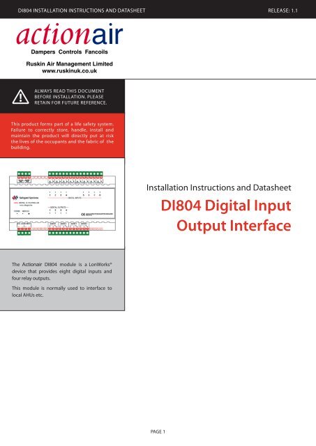
DI804 Installation Instructions and Datasheet release: 1.1Always READ this documentBEFORE INSTALLATION. PleaseRetain for future reference.This product forms part of a life safety system.Failure to correctly store, handle, install andmaintain the product will directly put at riskthe lives of the occupants and the fabric of thebuilding.Installation Instructions and DatasheetDI804 Digital InputOutput InterfaceThe Actionair DI804 module is a LonWorks®device that provides eight digital inputs andfour relay outputs.This module is normally used to interface tolocal AHUs etc.PAGE
- Page 2 and 3: DI804 Installation Instructions and
- Page 4: DI804 Installation Instructions and
<strong>DI804</strong> Installation Instructions and Datasheet release: 1.1Always READ this documentBEFORE INSTALLATION. PleaseRetain for future reference.This product forms part of a life safety system.Failure to correctly store, handle, install andmaintain the product will directly put at riskthe lives of the occupants and the fabric of thebuilding.Installation Instructions and Datasheet<strong>DI804</strong> <strong>Digital</strong> <strong>Input</strong><strong>Output</strong> <strong>Interface</strong>The <strong>Actionair</strong> <strong>DI804</strong> module is a LonWorks®device that provides eight digital inputs andfour relay outputs.This module is normally used to interface tolocal AHUs etc.PAGE
<strong>DI804</strong> Installation Instructions and Datasheet release: 1.1Dimensions and MountingThe compact and robust design of the <strong>DI804</strong>enclosure allows the unit to be mounted to aduct, block wall or stud wall using 35mm DINrail.Ensure the <strong>DI804</strong> is accessible for futuremaintenance purposes.PreparationWiring Diagram• Only trained and qualified personnel should beallowed to install, replace or service this equipment.Installation should be in accordance with therelevant local safety standards.• The connectors can accommodate cable diametersup to 2.5mm 2 . It is recommended that all wires becrimped to ease installation and replacement of theproduct.Installation1. Disconnect the local supply before commencing anywork on the <strong>DI804</strong>.2. Wire the <strong>DI804</strong> in accordance with the wiringdiagram shown across.3. It is recommended that the network cables are notrun alongside any high voltage or high frequencysources. Also, network cables must not be mixed onan individual network as they have very differentelectrical characteristics and could render thesystem unreliable.4. Once wiring is complete, apply power to the <strong>DI804</strong>.The green power LED should illuminate to indicatethe presence of power.5. The <strong>DI804</strong> is now ready to be configured using astandard LonWorks tool such as LonMaker or theSafegard system.LED BehaviourWink function: Service LED flashes for 5s.Active inputs and outputs (failsafe) are indicated bytheir respective LEDs.PAGE
<strong>DI804</strong> Installation Instructions and Datasheet release: 1.1<strong>Input</strong>s<strong>Input</strong> Wiring• The volt free input connectors are numbered 35 - 50.• Wire the first input as shown across and repeat forsubsequent inputs.• Please note that the input channels are not opticallyisolated and are independent of one another;therefore, use of a common ground between inputsshould be avoided.• The input cable diameter should be 1mm 2 or 1.5mm 2• Limit cable runs to 100m and avoid running inputcables near sources of mains or noisy environments.35 36INPutconnector NumberINPUT 1 35, 36INPUT 2 37, 38INPUT 3 39, 40INPUT 4 41, 42INPUT 5 43, 44INPUT 6 45, 46INPUT 7 47, 48INPUT 8 49, 5011External swequipm<strong>Output</strong>s• The relay output connectors are numbered 10 - 21.• Wire the first output as shown across and repeat forsubsequent outputs.• It is the user’s responsibility to ensure the switchedequipment is adequately protected.• The two terminal wires from each output shouldbe tie wrapped together to prevent slippage when35 36switching mains equipment.<strong>Output</strong> Wiring11 12External switchedequipmentOUTPutconnector NumberOUTPUT 1 11, 12OUTPUT 2 14, 15OUTPUT 3 17, 18OUTPUT 4 0, 21PAGE
<strong>DI804</strong> Installation Instructions and Datasheet release: 1.1SpecificationLonWorksNeuron chipTransceiver typeService functionsSupply<strong>Input</strong> voltageFT 3150 V13, 10 MHztP/FT-10Maximum power consumption 10 W<strong>Input</strong>sContact typeSense current<strong>Output</strong>sContact typeMaximum switched loadservice pin, service LED andneuron ID self-adhesive tag(24 ± 2.4) V AC, 50 Hz(24 ± 2.4) V DCnon-isolated dry contacts15 mA at 12 V DCsPCO mechanicalrelay contacts3 A at 230 V AC3 A at 30 V DCEnvironmentalOperating temperature -5 °C to 70 °CStorage temperature -20 °C to 70 °CHumidity 5 % RH to 90 % RH at 70 °CMaximum altitudeConformance2000 memc en 55022en 61000-6-3EnclosureMaterial lexan 940 and Noryl V0-1550IP rating IP 20Flammability ul 94V-0Pollution category 2Dimensions157 mm x 86 mm x 58 mm(L x W x D)complies with European standardsWARNING: The responsible body shall be made aware that, if the equipment is used in a manner not specified by themanufacturer, the protection provided by the equipment may be impaired.LonWorks, LonMark, LonMaker and the 3150 are trademarks of Echelon Corporation registered in the United States and othercountries. All other trademarks are acknowledged.Ruskin Air Management LimitedSouth Street, Whitstable, KentCT5 3DU England.Tel: 01227 276100Fax: 01227 264262Email: sales@actionair.co.ukWebsite: www.actionair.co.uk


