Intorq BFK461 - Manual PDF - Industrial Clutch Parts Limited
Intorq BFK461 - Manual PDF - Industrial Clutch Parts Limited
Intorq BFK461 - Manual PDF - Industrial Clutch Parts Limited

Create successful ePaper yourself
Turn your PDF publications into a flip-book with our unique Google optimized e-Paper software.
j | BA 14.0193−EN | 01/2009iContents1 Preface and general information . . . . . . . . . . . . . . . . . . . . . . . . . . . . . . . . . . . . . . . 51.1 About these Operating Instructions . . . . . . . . . . . . . . . . . . . . . . . . . . . . . . . . . . . 51.2 Terminology used . . . . . . . . . . . . . . . . . . . . . . . . . . . . . . . . . . . . . . . . . . . . . . . . . 51.3 Scope of supply . . . . . . . . . . . . . . . . . . . . . . . . . . . . . . . . . . . . . . . . . . . . . . . . . . 51.4 Disposal . . . . . . . . . . . . . . . . . . . . . . . . . . . . . . . . . . . . . . . . . . . . . . . . . . . . . . . . 51.5 Drive systems . . . . . . . . . . . . . . . . . . . . . . . . . . . . . . . . . . . . . . . . . . . . . . . . . . . . 61.6 Legal regulations . . . . . . . . . . . . . . . . . . . . . . . . . . . . . . . . . . . . . . . . . . . . . . . . . 62 Safety instructions . . . . . . . . . . . . . . . . . . . . . . . . . . . . . . . . . . . . . . . . . . . . . . . . . . . 72.1 General safety information . . . . . . . . . . . . . . . . . . . . . . . . . . . . . . . . . . . . . . . . . . 72.2 General application notes . . . . . . . . . . . . . . . . . . . . . . . . . . . . . . . . . . . . . . . . . . . 72.3 Application as directed . . . . . . . . . . . . . . . . . . . . . . . . . . . . . . . . . . . . . . . . . . . . . 82.4 Notes used . . . . . . . . . . . . . . . . . . . . . . . . . . . . . . . . . . . . . . . . . . . . . . . . . . . . . . 93 Technical data . . . . . . . . . . . . . . . . . . . . . . . . . . . . . . . . . . . . . . . . . . . . . . . . . . . . . . . 103.1 Product description . . . . . . . . . . . . . . . . . . . . . . . . . . . . . . . . . . . . . . . . . . . . . . . 103.2 Rated torques . . . . . . . . . . . . . . . . . . . . . . . . . . . . . . . . . . . . . . . . . . . . . . . . . . . 123.3 Rated data . . . . . . . . . . . . . . . . . . . . . . . . . . . . . . . . . . . . . . . . . . . . . . . . . . . . . . 123.4 Operating times . . . . . . . . . . . . . . . . . . . . . . . . . . . . . . . . . . . . . . . . . . . . . . . . . . 143.5 Operating frequency / friction work . . . . . . . . . . . . . . . . . . . . . . . . . . . . . . . . . . 153.6 Emission . . . . . . . . . . . . . . . . . . . . . . . . . . . . . . . . . . . . . . . . . . . . . . . . . . . . . . . 164 Mechanical installation . . . . . . . . . . . . . . . . . . . . . . . . . . . . . . . . . . . . . . . . . . . . . . . . 174.1 Necessary tools . . . . . . . . . . . . . . . . . . . . . . . . . . . . . . . . . . . . . . . . . . . . . . . . . . 174.2 Mounting . . . . . . . . . . . . . . . . . . . . . . . . . . . . . . . . . . . . . . . . . . . . . . . . . . . . . . . 184.3 Installation . . . . . . . . . . . . . . . . . . . . . . . . . . . . . . . . . . . . . . . . . . . . . . . . . . . . . . 185 Electrical installation . . . . . . . . . . . . . . . . . . . . . . . . . . . . . . . . . . . . . . . . . . . . . . . . . 205.1 Bridge/half−wave rectifiers . . . . . . . . . . . . . . . . . . . . . . . . . . . . . . . . . . . . . . . . . 205.2 Electrical connection . . . . . . . . . . . . . . . . . . . . . . . . . . . . . . . . . . . . . . . . . . . . . . 226 Commissioning and operation . . . . . . . . . . . . . . . . . . . . . . . . . . . . . . . . . . . . . . . . . . 256.1 Functional test . . . . . . . . . . . . . . . . . . . . . . . . . . . . . . . . . . . . . . . . . . . . . . . . . . . 256.2 During operation . . . . . . . . . . . . . . . . . . . . . . . . . . . . . . . . . . . . . . . . . . . . . . . . . 257 Maintenance/repair . . . . . . . . . . . . . . . . . . . . . . . . . . . . . . . . . . . . . . . . . . . . . . . . . . 267.1 Wear of spring−applied brakes . . . . . . . . . . . . . . . . . . . . . . . . . . . . . . . . . . . . . . . 267.2 Inspections . . . . . . . . . . . . . . . . . . . . . . . . . . . . . . . . . . . . . . . . . . . . . . . . . . . . . . 277.3 Maintenance . . . . . . . . . . . . . . . . . . . . . . . . . . . . . . . . . . . . . . . . . . . . . . . . . . . . 287.4 Spare−parts list . . . . . . . . . . . . . . . . . . . . . . . . . . . . . . . . . . . . . . . . . . . . . . . . . . 308 Troubleshooting and fault elimination . . . . . . . . . . . . . . . . . . . . . . . . . . . . . . . . . . . 314www.<strong>Industrial</strong><strong>Clutch</strong>.com
j | BA 14.0193−EN | 01/20091 Preface and general informationi1 Preface and general information1.1 About these Operating Instructions| These Operating Instructions will help you to work safely on and with thespring−applied brake with electromagnetic release. They contain safety instructionsthat must be followed.| All persons working on or with the electromagnetically released spring−applied brakesmust have the Operating Instructions available and observe the information and notesrelevant for them.| The Operating Instructions must always be in a complete and perfectly readablecondition.1.2 Terminology usedTermSpring−applied brakeDrive systemIn the following text used forSpring−applied brake with electromagnetic releaseDrive systems with spring−applied brakes and other drive components1.3 Scope of supply| The drive systems are combined individually according to a modular design. The scopeof delivery is indicated in the accompanying papers.| After receipt of the delivery, check immediately whether it corresponds to theaccompanying papers. INTORQ does not grant any warranty for deficiencies claimedsubsequently. Claim– visible transport damage immediately to the forwarder.– visible deficiencies / incompleteness immediately to INTORQ GmbH & Co.KG.1.4 DisposalThe spring−applied brake consists of different types of material.| Recycle metals and plastics.| Ensure professional disposal of assembled PCBs according to applicableenvironmental regulations.www.<strong>Industrial</strong><strong>Clutch</strong>.com5
j | BA 14.0193−EN | 01/20091Preface and general information1.5 Drive systems1.5.1 LabellingDrive systems and components are unambiguously designated by the indications on thenameplate.Manufacturer: INTORQ GmbH & Co KG, Wülmser Weg 5, D−31855 Aerzen| The spring−applied INTORQ brake is also delivered in single modules and individuallycombined to its modular design. The data − package labels, nameplate, and type codein particular − apply to the complete stator.| If single modules are delivered, the labelling is missing.1.6 Legal regulationsLiability| The information, data and notes in these Operating Instructions met the state of theart at the time of printing. Claims referring to drive systems which have already beensupplied cannot be derived from the information, illustrations and descriptions.| We do not accept any liability for damage and operating interference caused by:– inappropriate use– unauthorised modifications to the drive system– improper working on and with the drive system– operating faults– disregarding these Operating InstructionsWarranty| Terms of warranty: see terms of sale and delivery of INTORQ GmbH & Co. KG.| Warranty claims must be made to INTORQ immediately after detecting defects orfaults.| The warranty is void in all cases where liability claims cannot be made.6www.<strong>Industrial</strong><strong>Clutch</strong>.com
j | BA 14.0193−EN | 01/20092 Safety instructionsi2 Safety instructions2.1 General safety information| These safety notes do not claim to be complete. If any questions or problems occur,please contact INTORQ GmbH & Co. KG.| The spring−applied brake met the state of the art at the time of delivery and isgenerally safe to operate.| It must be ensured that only qualified personnel work on and with the INTORQspring−applied brakes.Qualified personnel are persons who, because of their training, experience and knowledgeof all applicable standards and regulations as well as of all operating circumstances, havebeen entitled by the person responsible for the safety of the system to work on and withthe system and to see and avoid all possible dangers.(Definition for personnel to IEC 364)| The spring−applied brake is hazardous to persons, the spring−applied brake itself andother properties of the operator if– non−qualified personnel work on and with the spring−applied brake.– the spring−applied brake is used inappropriately.| The spring−applied brakes must be planned in such a way that if they are correctlyinstalled and used for their designed purpose in fault−free operation, they fulfil theirfunction and do not put any persons at risk. This also applies to the interaction thereofwith the overall system.| Take appropriate measures to ensure that the failure of the spring−applied brake willnot lead to damage to material.2.2 General application notes| Do not operate the spring−applied brake unless it is in perfect condition.| Retrofittings, modifications and changes of the drive system are generally forbidden. Inany case, INTORQ GmbH & Co. KG must be contacted beforehand.| The friction lining and the friction surfaces must be carefully protected from oil orgrease since even small amounts of lubricants reduce the brake torque considerably.| The rated torques specified in the catalog and in these Operating Instructions aretorques after a run−in phase.| The braking torque will usually not be influenced if the brake is used under theenvironmental conditions that apply to IP66. Because of the numerous possibilities ofusing the brake, it is however necessary to check the functionality of all mechanicalcomponents under the corresponding operating conditions.| Protect electrical connections against contact.| The brake consists of different types of material which must be recycled or disposedof according to applicable environmental regulations.www.<strong>Industrial</strong><strong>Clutch</strong>.com7
j | BA 14.0193−EN | 01/20092Safety instructions2.3 Application as directed| Drive systems– are intended for use in machinery and systems.– must only be used for the purposes ordered and confirmed.– must only be operated under the ambient conditions prescribed in these OperatingInstructions.– must not be operated beyond their corresponding power limits.Any other use shall be deemed inappropriate!Possible applications of the INTORQ spring−applied brake| No explosive or aggressive atmosphere.| Humidity, no restrictions.| Ambient temperature: −20°C to +40°C.| Thermal class F (+155°C)– all materials used are designed for a max. operating temperature of 155°C.8www.<strong>Industrial</strong><strong>Clutch</strong>.com
j | BA 14.0193−EN | 01/20092 Safety instructionsi2.4 Notes usedThe following pictographs and signal words are used in this documentation to indicate dangersand important information:Safety instructionsStructure of safety instructions: Danger!Characterises the type and severity of dangerNoteDescribes the dangerPossible consequences:| List of possible consequences if the safety instructions are disregarded.Protective measure:| List of protective measures to avoid the danger.Pictograph and signal word Danger! Danger! Stop!MeaningDanger of personal injury through dangerous electrical voltageReference to an imminent danger that may result in death or seriouspersonal injury if the corresponding measures are not taken.Danger of personal injury through a general source of dangerReference to an imminent danger that may result in death or seriouspersonal injury if the corresponding measures are not taken.Danger of property damageReference to a possible danger that may result in property damage if thecorresponding measures are not taken.Application notesPictograph and signal word Note! Tip!MeaningImportant note to ensure troublefree operationUseful tip for simple handlingReference to another documentationwww.<strong>Industrial</strong><strong>Clutch</strong>.com9
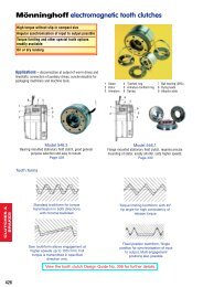
j | BA 14.0193−EN | 01/20093Technical data3 Technical data3.1 Product description<strong>BFK461</strong>10−004.isoFig. 1Structure of an INTORQ <strong>BFK461</strong> spring−applied brake1 Armature plate 6 Flange (option) 7.2 O−ring2 Compression spring 6.1 O−ring 8 Cheese head screwDIN9123 Rotor with friction lining 7 Stator 8.1 USIT ring4 Hub 7.1 Cover10www.<strong>Industrial</strong><strong>Clutch</strong>.com
j | BA 14.0193−EN | 01/20093 Technical datai3.1.1 General informationThe INTORQ <strong>BFK461</strong>− spring−applied brake is a single−disk brake with two frictionsurfaces. The brake torque is generated by several compression springs (2) by friction. Thebrake is released electromagnetically.The spring−applied brake converts mechanical work and kinetic energy into heat. Foroperating speed, see chapter 3.3 Rated data. Due to the static brake torque, the brake canhold loads without speed difference. Emergency braking is possible at high speed, see chapter3.3 Rated data. The more friction work the higher the wear. Please take into account that thefriction value and thus the brake torque depend on the speed. Stop!Due to the design of the stator, the air gap of the INTORQ <strong>BFK461</strong>spring−applied brake cannot be readjusted. In case of wear, replace the rotor(3), if necessary.To guarantee the IP66 enclosure, an O−ring is used to seal the brake on the motor flange side(6.1 and as option 7.2). A cover (7.1) closes the stator (7) on the back. Alternatively, you canalso use a V−seal ring as axial shaft seal (is not part of the INTORQ delivery package). Note!Mount USIT rings (8.1) underneath the fixing screws (8) to avoid the penetrationof dust and fluid into the interior of the brake!3.1.2 BrakingDuring braking, the rotor (3), which is axially movable on the hub (4), is pressed againstthe friction surface − via the armature plate (1) − by means of the inner and outer springs(2). The asbestos−free friction linings ensure a high brake torque with low wear. The braketorque is transmitted between hub (4) and rotor (3) via the splines.3.1.3 Brake releaseIn braked state, there is an air gap "s air" between stator (7) and armature plate (1). To releasethe brake, the stator coil (7) is excited with the DC voltage provided. The magnetic forcegenerated attracts the armature plate (1) towards the stator (7) against the spring force. Therotor (3) is then released and can rotate freely.www.<strong>Industrial</strong><strong>Clutch</strong>.com11
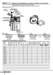
j | BA 14.0193−EN | 01/20093Technical data3.2 Rated torquesSizes 06 08 10 12 14 16 18n = 100 min −1 6 12 23 40 75 90 1652 3.5 7 14 25 35 652.5 5 9 18 40 45 803 6 11 23 45 55 1003.5 7 14 27 55 60 115Rated torques [Nm],referring to the4 8 16 32 60 70 130relative speed4.5 9 18 36 65 80 15080 100 185105 200125 235Tab. 1Rated torques in [Nm] − INTORQ <strong>BFK461</strong>Standard brake torque3.3 Rated dataTypeINTORQ <strong>BFK461</strong>−06 20INTORQ <strong>BFK461</strong>−08 25INTORQ <strong>BFK461</strong>−103) ElectricalCoil resistance R 20 []power P 20Voltage U Rated currentI N[W] [V] [A] rated max. min.3233INTORQ <strong>BFK461</strong>−12 40INTORQ <strong>BFK461</strong>−14 53INTORQ <strong>BFK461</strong>−16 56INTORQ <strong>BFK461</strong>−18 851032051032051032051032051032051032051032050.1940.0980.2430.1220.3110.1610.3880.1950.5150.2590.5440.2730.8250.415530.52101.0424.41681.0331.51273.5265.21051.0200.2792.9189.5750.5124.8494.4564.92269.0449.81807.0349.81356.0279.81114.0210.2836.5198.9791.7130.4519.1496.61933.0398.91555.0313.31191.0250.6987.6190.2749.3180.0709.2119.2469.7Tab. 2 Rated data − INTORQ <strong>BFK461</strong>spring−applied brake3) Other voltages (24V; 96V; 170V; 180V; 190V) on request12www.<strong>Industrial</strong><strong>Clutch</strong>.com
13TypeINTORQ <strong>BFK461</strong>−06INTORQ <strong>BFK461</strong>−08INTORQ <strong>BFK461</strong>−10INTORQ <strong>BFK461</strong>−12INTORQ <strong>BFK461</strong>−14INTORQ <strong>BFK461</strong>−16INTORQ <strong>BFK461</strong>−18Rated torque Rated torque at n 1) 0 [Nm] Max. Brake mass Outermin −1 n 0max.at n = 100speeddiameterM 1) K [Nm] 1500 3000 max.horizontalwithoutwithPitch circleTightening torqueof fixing screws[min −1 ] Flange [kg] Flange [kg] [mm] [mm] Thread [Nm] rated 2)[mm]Air gap s air ±0.1max.[mm]0.6Moment ofinertia ofrotorRotor thickness[kg cm 2 ] min. [mm] max. [mm]43.5 3.2 2.65.412400 1.2 1.4 87 72 3 x M4 3.00.130 65.2 4.8 3.9−0.056 0.4 5.686.8 6.2 5.30.66.410100 2.2 2.57 103 90 3 x M5 5.90.450 710.2 9.3 7.9−0.0512 0.45 6.550.21613.3 12.2 10.60.78.38300 4.1 4.9 130 1122.000 919.1 17.5 15.2−0.123 0.5 8.53 x M6 10.13225.9 23.7 21.10.69.36700 6.1 7.2 148 1324.500 1037.3 34.0 30.4−0.146 0.4 9.56048.0 43.8 40.20.89.26000 8.9 10.5 165 1456.300 1072.0 65.7 60.3−0.190 0.5 9.53 x M80.38063.2 57.6 52.80.910.65300 14.0 16.4 200 17024.615.000 11.598.8 90.0 82.5−0.1125 0.6 10.9150115.5 105.0 99.01.012.04400 16.7 19.6 221 196 6 x M8 0.429.000 13181.0 164.5 155.0−0.1235 0.6 12.41) Minimum rated torque when all components are run in2) Minimum air gap, effective value results from the sum tolerances of the single components.www.<strong>Industrial</strong><strong>Clutch</strong>.com3 Technical dataij | BA 14.0193−EN | 01/2009
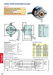
j | BA 14.0193−EN | 01/20093Technical data3.4 Operating timesBFKXXX−001.isoFig. 2Operating times of the INTORQ spring−applied brakest 1 Engagement time t 11 Reaction delay during engagementt 2 Disengagement time (up to M = 0.1 M r ) t 12 Rise time of the brake torqueTypeRated brake torqueat n = 100 min −1Friction work perswitching operationTransition operatingfrequencyOperating times [ms] at s LüNenn and 0.7 x I NDC engagementDisengagementM 1) K [Nm] Q E [J] S hü [h −1 ] t 11 t 12 t 1 t 2INTORQ <strong>BFK461</strong>−06 4 3000 79 14 29 43 62INTORQ <strong>BFK461</strong>−08 8 7500 50 39 28 67 61INTORQ <strong>BFK461</strong>−10 16 12000 40 30 40 70 100INTORQ <strong>BFK461</strong>−12 32 24000 30 42 38 80 150INTORQ <strong>BFK461</strong>−14 60 30000 28 26 55 81 230INTORQ <strong>BFK461</strong>−16 80 36000 27 30 48 78 335INTORQ <strong>BFK461</strong>−18 150 60000 20 68 68 136 320Tab. 3Switching energy − operating frequency − operating times1) Minimum brake torque when all components are run inThe transition from the state without brake torque to the steady brake torque is not withoutdelay. The engagement times are valid for switching on the DC side with an induction voltageof approx. 5 to 10 times nominal voltage. The chart shows the delay during engagement t 11 ,the rise time of the brake torque t 12 and the engagement time t 1 = t 11 + t 12 , as well as thedisengagement time t 2 .Disengagement timeThe disengagement time is not influenced by DC or AC switching operations. It can only beshortened by special equipment for fast−response excitation or overexcitation.14www.<strong>Industrial</strong><strong>Clutch</strong>.com
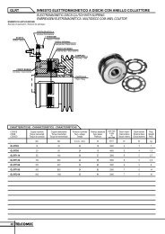
j | BA 14.0193−EN | 01/20093 Technical dataiEngagement timeWith switching on the AC side, the engagement times are prolonged approximately by thefactor 10, for connection see page 23, Fig. 7.Spark suppressors for the rated voltages, which are to be connected in parallel to the contact,are available for engagement on the DC side. If this is not admissible for safety reasons, e.g.with hoists and lifts, the spark suppressor can also be connected in parallel to the brake coil,for connection see page 23, Fig. 8.3.5 Operating frequency / friction work<strong>BFK461</strong>XX−008.isoFig. 3Friction work as a function of the operating frequencyS fperm S tflnН1 Q Q ES tfQ perm Q E1 eS f The permissible operating frequency "S hperm " depends on the friction work "Q" (see Fig. 3).An operating frequency of "S h " results in the permissible friction work "Q perm ".With high speed and friction work, the wear increases strongly, because very hightemperatures occur at the friction faces for a short time.www.<strong>Industrial</strong><strong>Clutch</strong>.com15
j | BA 14.0193−EN | 01/20093Technical data3.6 EmissionElectromagnetic compatibility Note!The user must ensure compliance with EMC Directive 2004/108/EC usingappropriate controls and switching devices.If an INTORQ rectifier is used for the DC switching of an INTORQ spring−applied brake andif the operating frequency exceeds five switching operations per minute, the use of amains filter is required. If the INTORQ spring−applied brake uses a rectifier of anothermanufacturer for the switching, it may become necessary to connect a spark suppressorin parallel with the AC voltage. Spark suppressor according to coil voltage on request.HeatSince the brake converts kinetic energy as well as mechanical and electrical energy into heat,the surface temperature varies considerably, depending on the operating conditions andpossible heat dissipation. Under unfavourable conditions, the surface temperature can reach130C.NoisesThe switching noises during engagement and disengagement depend on the air gap "s air " andthe brake size.Depending on the natural oscillation after installation, operating conditions and state of thefriction faces, the brake may squeak during braking.OthersThe abrasion of the friction parts produces dust.In case of high load, the friction face will become so hot that odours may occur.16www.<strong>Industrial</strong><strong>Clutch</strong>.com
j | BA 14.0193−EN | 01/20094 Mechanical installationi4 Mechanical installation4.1 Necessary toolsType Torque wrench Insertion for hexagon socket screwsINTORQ <strong>BFK461</strong>−06INTORQ <strong>BFK461</strong>−08INTORQ <strong>BFK461</strong>−10INTORQ <strong>BFK461</strong>−12INTORQ <strong>BFK461</strong>−14INTORQ <strong>BFK461</strong>−16INTORQ <strong>BFK461</strong>−18*Measuring range [Nm]Wrench size [mm]3x 1 / 4 " square4x 1 / 4 " square1 − 125x 1 / 4 " square20 − 100 6x 1 / 2 " square* for flange mounting insertion with journal guideMultimeterCaliper gaugewww.<strong>Industrial</strong><strong>Clutch</strong>.com17
j | BA 14.0193−EN | 01/20094Mechanical installation4.2 Mounting4.2.1 Preparation1. Unpack spring−applied brake.2. Check for completeness.3. Check nameplate data, especially rated voltage.4.3 Installation Stop!Toothed hub and screws must not be lubricated with grease or oil!4.3.1 Installation of the hub onto the shaft<strong>BFK461</strong>10−003.isoFig. 4Installation of the hub onto the shaft3.0 Hub3.1 Circlip10.0 Endshield1. Press hub (3.0) onto the shaft2. Secure hub against axial displacement, e.g. using a circlip (3.1).18www.<strong>Industrial</strong><strong>Clutch</strong>.com
j | BA 14.0193−EN | 01/20094 Mechanical installationi4.3.2 Installation of the brake1. Installation of the hub (3.0), chapter 4.3.12. Push the spring−applied brake (1.0) onto the hub (3.0).1. 2.<strong>BFK461</strong>10−003−a.iso <strong>BFK461</strong>10−005.iso3. Screw the spring−applied brake (1.0) onto the endshield (10.0) using the integratedfixing screws.4. Tighten the screws (8.1) evenly (for torques, see the table Rated data, chapter 3.3).3. 4.U = X D.C. ±10%<strong>BFK461</strong>10−006.isoNoteOILwww.<strong>Industrial</strong><strong>Clutch</strong>.com19
j | BA 14.0193−EN | 01/20095Electrical installation5 Electrical installation5.1 Bridge/half−wave rectifiersBEG−561− − Bridge/half−wave rectifiers are used for the supply of electromagnetic spring−applied DCbrakes which have been released for operation with such rectifiers. Any other use is onlypermitted with the explicit written approval of INTORQ.After a defined overexcitation time, the bridge/half−wave rectifiers change from bridgerectification to half−wave rectification. Depending on the dimensioning of the load, theswitching performance can thus be improved or the power can be derated.Terminals 3 and 4 are in the DC circuit of the brake. The induction voltage peak for DCswitching (see circuit diagram "Reduced switch−off times") is limited by an integratedovervoltage protection at terminals 5 and 6.Dimensions52,6Possible installations21,554,31,846,9-0,151,9-0,13,4423,438413169140Typ BEG-561-440-030-1440V~ 1,5/0,75A t ü=0,30sFig. 5Dimensions and possible installations of bridge/half−wave rectifier5.1.1 Technical dataRectifier typeBridge/half−wave rectifierOutput voltage for bridge rectification 0.9 x U 1Output voltage for half−wave rectification 0.45 x U 1Ambient temperature (storage/operation) [C°] −25 ... +7020www.<strong>Industrial</strong><strong>Clutch</strong>.com
j | BA 14.0193−EN | 01/20095 Electrical installationiType Input voltage U 1(40 Hz ... 60 Hz)Max. current I max.Overexcitation time t o ( 20%)min.[V ]rated[V ]max.[V ]bridge[A]half−wave[A]with U 1 min[s]with U 1rated [s]with U 1max [s]BEG−561−255−0300.430 0.300 0.270160 230 255 3.0 1.5BEG−561−255−130 1.870 1.300 1.170BEG−561−440−030−11.5 0.75 0.500 0.300 0.270230 400 440BEG−561−440−130 3.0 1.5 2.300 1.300 1.200Tab. 4Data for bridge/half−wave rectifier type BEG−561Input voltage U 1 (40 ... 60 Hz)5.1.2 Permissible current load − ambient temperature1 For screw assembly with metal surface (good heat dissipation)2 For other assembly (e.g. glue)BFKXXX−008−a.isowww.<strong>Industrial</strong><strong>Clutch</strong>.com21
j | BA 14.0193−EN | 01/20095Electrical installation5.2 Electrical connection Danger!| Electrical connection must only be carried out by skilled personnel!| Connections must only be made when the equipment is de−energised! Dangerthrough unintended starts or electric shocks. Stop!| It must be ensured that the supply voltage corresponds to the nameplatedata.| Voltages must be adapted to the local environment!Circuit proposalsBFKXXX−005.isoFig. 6Switching parallel to the motor, extremely delayed engagement Bridge rectifier Half−wave rectifier22www.<strong>Industrial</strong><strong>Clutch</strong>.com
j | BA 14.0193−EN | 01/20095 Electrical installationiBFKXXX−007.isoFig. 7AC switching, delayed engagement Bridge rectifier Half−wave rectifierBFKXXX−002.isoFig. 8DC switching, normal engagement Bridge rectifier Half−wave rectifierwww.<strong>Industrial</strong><strong>Clutch</strong>.com23
j | BA 14.0193−EN | 01/20095Electrical installationBFKXXX−006.isoFig. 9Separated DC voltage, DC switchingConnection diagram also valid for star connection DC voltage (e.g. 24V) Spark suppressor Stop!For switching on the DC side the brake must be operated with a sparksuppressor to avoid impermissible overvoltages.24www.<strong>Industrial</strong><strong>Clutch</strong>.com
j | BA 14.0193−EN | 01/20096 Commissioning and operationi6 Commissioning and operation Danger!The live connections and the rotating rotor must not be touched.The drive must not be running when checking the brake.6.1 Functional testIn the event of failures, refer to the troubleshooting table in chapter 8. If the fault cannot beeliminated, please contact the aftersales service.6.1.1 Checking the voltage Danger!The brake must be free of residual torque. The motor must not rotate. Danger!Live connections must not be touched.1. Remove two bridges from the motor terminals. Do not switch off the DC brake supply.When connecting the rectifier to the neutral point of the motor, the PE conductor mustalso be connected to this point.2. Connect the mains supply.3. Measure the DC voltage at the brake.– Compare the DC voltage measured with the voltage specified on the nameplate. A10 % deviation is permissible.4. Switch off the current.5. Bolt bridges to the motor terminals. Remove additional PEN conductor.6.2 During operation| Check the brake regularly during operation. Take special care of:– unusual noises and temperatures– loose fixing elements– the state of the cables.| In the event of failures, refer to the troubleshooting table in chapter 8. If the faultcannot be eliminated, please contact the aftersales service.www.<strong>Industrial</strong><strong>Clutch</strong>.com25
j | BA 14.0193−EN | 01/20097Maintenance/repair7 Maintenance/repair7.1 Wear of spring−applied brakesINTORQ spring−applied brakes are wear−resistant and designed for long maintenanceintervals. The friction lining and the mechanical brake components are subject tofunction−related wear. For safe and trouble−free operation, the brake must be checked andreadjusted at regular intervals, and, if necessary, be replaced.The following table describes different causes of wear and their effects on the componentsof the spring−applied brake. For calculating the service life of rotor and brake and determiningthe maintenance intervals to be observed, the relevant factors of influence must be quantified.The most important factors are the friction work, initial speed of braking and the operatingfrequency. If several of the causes of wear indicated for the friction lining occur in anapplication at the same time, the influencing factors must be added for calculating the wear.The INTORQ Select dimensioning program can be used to calculate the maintenanceintervals.Component Cause Effect Influencing factorsFriction lining Braking during operationEmergency stopsOverlapping wear during start andstop of driveActive braking via the drive motorwith support of brake (quick stop)Starting wear in case of motorWear of friction liningFriction workNumber of start/stop cyclesmounting position with verticalshaft, even when the brake is notappliedArmature plate and Rubbing of brake liningArmature plate and flangeare run in Friction workflangeSplining of brake rotor Relative movements and shocksbetween brake rotor and brakeshaftWear of splining (primarily on therotor side)Number of start/stop cyclesArmature plate supportSpringsLoad alternation and jerks in thebacklash between armature plate,sleeve bolts and guide boltAxial load cycle and shear stress ofsprings through radial backlash onreversal of armature plateBreaking of armature plate, sleevebolts and guide boltReduced spring force or fatiguefailureNumber of start/stop cycles,braking torqueNumber of switching operations ofbrake26www.<strong>Industrial</strong><strong>Clutch</strong>.com
j | BA 14.0193−EN | 01/20097 Maintenance/repairi7.2 InspectionsTo ensure safe and trouble−free operation, spring−applied brakes must be checked andmaintained at regular intervals. Servicing can be made easier if good accessability of thebrakes is provided in the plant. This must be considered when installing the drives in the plant.Primarily, the necessary maintenance intervals for industrial brakes result from the load duringoperation. When calculating the maintenance interval, all causes for wear must be taken intoaccount (see chapter 7.1). For brakes with low loads such as holding brakes with emergencystop, we recommend a regular inspection at a fixed time interval. To reduce the cost, theinspection can be carried out along with other regular maintenance work in the plant ifnecessary.If the brakes are not maintained, failures, production outages or plant damages may be theresult. Thus, a maintenance concept adapted to the operating conditions and loads of thebrake must be developed for every application. The maintenance intervals and maintenancework listed in the following table must be scheduled for the spring−applied INTORQ brake.7.2.1 Maintenance intervalsService brakes | according to service life calculation| otherwise every six months| after 4000 operating hours at the latestHolding brakes with emergengy stop | at least every 2 years| after 1 million cycles at the latest7.2.2 Checking the component partsfor built−on brakes | Check release function and control| Measure rotor thickness (replace rotor if necessary)| Thermal damage to armature plate or flange (dark bluetarnishing)after removing the brake | Check clearance of the rotor toothing (replace rotorswith worn out teeth)| Play of torque plate at pins and armature plate| Check springs for damage| Check armature plate and flange/endshield– Evenness sizes 06...12 > 0.06 mm– Evenness from size 14 > 0.1 mm– Max. run−in depth = rated air gap of brake sizesee chapter7.3.3see chapter7.3.1see chapter7.3.2www.<strong>Industrial</strong><strong>Clutch</strong>.com27
j | BA 14.0193−EN | 01/20097Maintenance/repair7.3 Maintenance Note!Brakes with defective armature plates, cheese head screws, springs or flangesmust be replaced completely.Please observe the following for inspections and maintenance operations:| Remove impurities through oil and grease using brake cleaning agents, ifnecessary, replace brake after finding out the cause of the contamination.Dirt deposits in the air gap between stator and armature plate impair thefunction of the brake and must be removed.| After replacing the rotor, the original braking torque will not be reached untilthe run−in operation of the friction surfaces has been completed. Afterreplacing the rotor, run−in armature plates and flanges have an increasedinitial rate of wear.7.3.1 Checking the rotor thickness Danger!Disconnect voltage. The brake must be free of residual load torque.1. Loosen connection cable.2. Unbolt fixing screws and remove brake from endshield. Observe connection cable.3. Pull rotor from hub.4. Measure the rotor thickness using a caliper gauge.5. Compare the measured rotor thickness with the minimum permissible rotor thickness(see chapter 3.3).6. If necessary, replace the rotor (see chapter 7.3.2).28www.<strong>Industrial</strong><strong>Clutch</strong>.com
j | BA 14.0193−EN | 01/20097 Maintenance/repairi7.3.2 Rotor replacement Danger!Disconnect voltage. The brake must be free of residual load torque.1. Loosen connection cable.2. Unbolt fixing screws and remove brake from endshield. Observe connection cable.3. Pull rotor from hub.4. Check hub splining. In case of wear, replace hub.5. Check friction surfaces.– In case of strong scoring at the flange, replace the flange.– If scoring occurs at the endshield, re−finish friction surface.6. Measure the rotor thickness using a caliper gauge and compare the values with thevalues given in chapter 3.3. If necessary, replace the rotor.7. Check the brake, chapter 7.2.8. If necessary, install new brake.9. Reconnect the supply cable. Note!After replacing the rotor, the original braking torque will not be reached until therun−in operation of the friction surfaces has been completed. After replacing therotor, run−in armature plates and flanges have an increased initial rate of wear.7.3.3 Release / voltage Danger!Live connections must not be touched.1. Observe the brake function during operation of the drive. The armature plate must beattracted and the rotor must move without residual torque.2. Measure the DC voltage at the brake.– Compare the DC voltage measured with the voltage specified on the nameplate. A10 % deviation is permissible.www.<strong>Industrial</strong><strong>Clutch</strong>.com29
j | BA 14.0193−EN | 01/20097Maintenance/repair7.4 Spare−parts listOnly parts with item numbers are available.The item numbers are only valid for the standard design.| Bore diameter in mm| Standard keyway to DIN 6885/1 P9<strong>BFK461</strong>10−007.isoFig. 10Spare parts for INTORQ <strong>BFK461</strong>−01...18spring−applied brakeItem Name Variant3.0 Rotor Size −−−−− −−−−− −−−−−4.0 Hub Size Bore −−−−−6.06.17.07.17.2FlangeO−ringStatorCoverO−ringSizeSize8.0 Set of fixing screws SizeVoltageRated torqueElectrical accessoriesSpark suppressor Coil voltage Coil power Order no.[V AC] [W]24 ... 5004579850 ... 120 045800up to 100120 ... 200 045801200 ... 250 41192630www.<strong>Industrial</strong><strong>Clutch</strong>.com
j | BA 14.0193−EN | 01/20098 Troubleshooting and fault elimination i8 Troubleshooting and fault eliminationIf any malfunctions should occur during operation of the drive system, please check thepossible causes using the following table. If the fault cannot be eliminated by one of the listedmeasures, please contact the aftersales service.Fault Cause RemedySpring−applied brake cannot bereleased, air gap is not zeroRotor not thick enoughVoltage too highVoltage too lowCoil is interrupted | Measure the coil resistance using a multimeter:– Replace the spring−applied brake when theresistance is too high.Coil has interturn fault or short circuit toground| Measure the coil resistance using a multimeter:– Compare the measured resistance with therated resistance. The rated data is given inchapter 3.3 Rated data. Replace thespring−applied brake when the resistance is toolow.| Test the coil for short circuit to ground using amultimeter:– If a short circuit to ground occurs, replace thespring−applied brake.| Check the brake voltage (see defective rectifier,voltage too low).Defective or wrong wiring | Check and correct wiring.| Check the cable using a multimeter:– Replace defective cable.Defective or wrong rectifier | Measure the DC voltage at the rectifier using amultimeter.When the DC voltage is zero:| Measure the AC voltage at the rectifier.When the AC voltage is zero:– Apply voltage– Check fuse– Check wiringWhen the AC voltage is ok:– Check rectifier– Replace defective rectifierWhen the DC voltage is too low:– Check rectifier– Half−wave rectifier used instead of bridgerectifier. Install bridge rectifier.– Defective diode, use an appropriate rectifier.| Check the coil for fault between turns and shortcircuit to ground.| If the rectifier defect occurs again, replace thespring−applied brake, even if you cannot find anyfault between turns or short circuit to ground. Thefault may occur later during heating−up.Air gap too big | Replace rotor for INTORQ <strong>BFK461</strong>−06...18spring−applied brake.Spring−applied brake has not beenreplaced in timeBrake voltage does not match therectifierBrake voltage does not match therectifierDefective rectifier diodeReplace spring−applied brake (chapter 4.3.1 and4.3.2)Adapt rectifier and brake voltage to each other.Adapt rectifier and brake voltage to each other.Replace rectifier by a suitable new one.AC voltage is not mains voltage Fuse missing or defective Select a connection with proper fusing.www.<strong>Industrial</strong><strong>Clutch</strong>.com31