

(jeb@oscalemag.com). - O Scale Trains Magazine Online
(jeb@oscalemag.com). - O Scale Trains Magazine Online
(jeb@oscalemag.com). - O Scale Trains Magazine Online

Create successful ePaper yourself
Turn your PDF publications into a flip-book with our unique Google optimized e-Paper software.
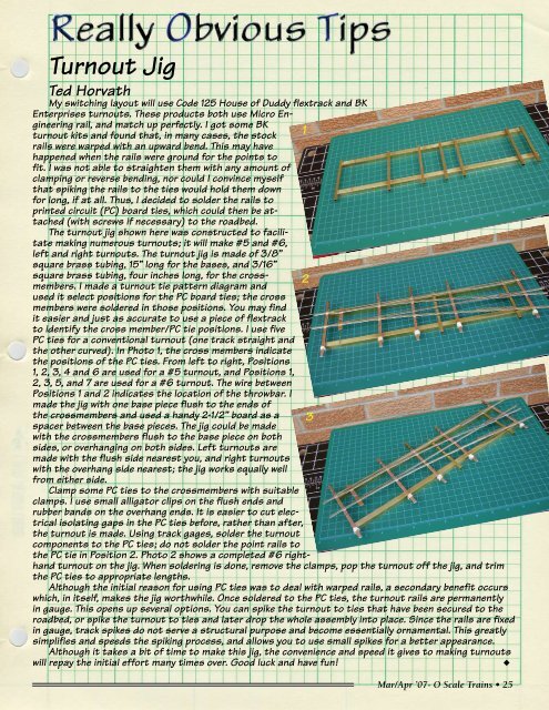
Turnout JigTed HorvathMy switching layout will use Code 125 House of Duddy flextrack and BKEnterprises turnouts. These products both use Micro Engineeringrail, and match up perfectly. I got some BKturnout kits and found that, in many cases, the stock 1rails were warped with an upward bend. This may havehappened when the rails were ground for the points tofit. I was not able to straighten them with any amount ofclamping or reverse bending, nor could I convince myselfthat spiking the rails to the ties would hold them downfor long, if at all. Thus, I decided to solder the rails toprinted circuit (PC) board ties, which could then be attached(with screws if necessary) to the roadbed.The turnout jig shown here was constructed to facilitatemaking numerous turnouts; it will make #5 and #6,left and right turnouts. The turnout jig is made of 3/8”square brass tubing, 15” long for the bases, and 3/16”square brass tubing, four inches long, for the crossmembers.I made a turnout tie pattern diagram and2used it select positions for the PC board ties; the crossmembers were soldered in those positions. You may findit easier and just as accurate to use a piece of flextrackto identify the cross member/PC tie positions. I use fivePC ties for a conventional turnout (one track straight andthe other curved). In Photo 1, the cross members indicatethe positions of the PC ties. From left to right, Positions1, 2, 3, 4 and 6 are used for a #5 turnout, and Positions 1,2, 3, 5, and 7 are used for a #6 turnout. The wire betweenPositions 1 and 2 indicates the location of the throwbar. Imade the jig with one base piece flush to the ends ofthe crossmembers and used a handy 2-1/2” board as a 3spacer between the base pieces. The jig could be madewith the crossmembers flush to the base piece on bothsides, or overhanging on both sides. Left turnouts aremade with the flush side nearest you, and right turnoutswith the overhang side nearest; the jig works equally wellfrom either side.Clamp some PC ties to the crossmembers with suitableclamps. I use small alligator clips on the flush ends andrubber bands on the overhang ends. It is easier to cut electricalisolating gaps in the PC ties before, rather than after,the turnout is made. Using track gages, solder the turnout<strong>com</strong>ponents to the PC ties; do not solder the point rails tothe PC tie in Position 2. Photo 2 shows a <strong>com</strong>pleted #6 righthandturnout on the jig. When soldering is done, remove the clamps, pop the turnout off the jig, and trimthe PC ties to appropriate lengths.Although the initial reason for using PC ties was to deal with warped rails, a secondary benefit occurswhich, in itself, makes the jig worthwhile. Once soldered to the PC ties, the turnout rails are permanentlyin gauge. This opens up several options. You can spike the turnout to ties that have been secured to theroadbed, or spike the turnout to ties and later drop the whole assembly into place. Since the rails are fixedin gauge, track spikes do not serve a structural purpose and be<strong>com</strong>e essentially ornamental. This greatlysimplifies and speeds the spiking process, and allows you to use small spikes for a better appearance.Although it takes a bit of time to make this jig, the convenience and speed it gives to making turnoutswill repay the initial effort many times over. Good luck and have fun!uMar/Apr ’07- O <strong>Scale</strong> <strong>Trains</strong> • 25


