

(jeb@oscalemag.com). - O Scale Trains Magazine Online
(jeb@oscalemag.com). - O Scale Trains Magazine Online
(jeb@oscalemag.com). - O Scale Trains Magazine Online

You also want an ePaper? Increase the reach of your titles
YUMPU automatically turns print PDFs into web optimized ePapers that Google loves.
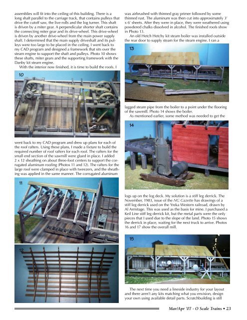
assemblies will fit into the ceiling of this building. There is along shaft parallel to the carriage track, that contains pulleys thatdrive the cutoff saw, the live-rolls and the log turner. This shaftis driven by a miter gear. A perpendicular shorter shaft containsthe connecting miter gear and its drive-wheel. This drive-wheelis driven by another drive-wheel from the main power supplyshaft. I determined that the main supply driveshaft and its pulleyswere too large to be placed in the ceiling. I went back tomy CAD program and designed a framework that sits over thesteam engine to support the shaft and pulleys. Photo 10 showsthese shafts, miter gears and the supporting framework with theDanby kit steam engine.With the interior now finished, it is time to build the roofs. I10was airbrushed with thinned gray primer followed by somethinned rust. The aluminum was then cut into approximately 3’x 6’ sheets. After they were in place, they were weathered usingpowdered chalks dissolved in alcohol. The finished roofs showin Photo 13.An old Hetch Hetchy kit steam boiler was installed outsidethe rear door to supply steam for the steam engine. I ran a13lagged steam pipe from the boiler to a point under the flooringof the sawmill. Photo 14 shows the boiler.As mentioned earlier, some method was needed to get the14went back to my CAD program and drew up plans for each ofthe roof rafters. Using these plans, I made a fixture to build therequired number of roof rafters for each roof. The rafters for thesmall end section of the sawmill were glued in place. I added2 x 12 sheathing on about three-foot centers to support the corrugatedaluminum roofing (Photos 11 and 12). The rafters for thelarge roof were clamped in place with tweezers, and the sheathingwas applied in the same manner. The corrugated aluminum11logs up on the log deck. My solution is a stiff leg derrick. TheNovember, 1983, issue of the NG Gazette has drawings of astiff leg derrick used on the Yreka Western railroad, drawn byAl Armitage. This was used as the basis for mine. I purchased aKeil Line stiff leg derrick kit, but the metal parts were the onlypieces that I used due to the slope of the land. Photo 15 showsthe derrick in place, waiting for the next truck to arrive. Photos16 and 17 show the overall mill.1512The next time you need a lineside industry for your layoutand there aren’t any kits matching what you envision, designyour own using available detail parts. Scratchbuilding is stillMar/Apr ’07 - O <strong>Scale</strong> <strong>Trains</strong> • 23


