


You also want an ePaper? Increase the reach of your titles
YUMPU automatically turns print PDFs into web optimized ePapers that Google loves.
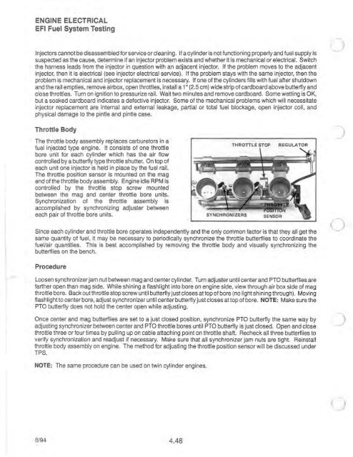
ENGINE ELECTRICALEFI Fuel System TestingInjectors cannot be disassembled for service or cleaning. If a cylinder is not functioning properly and fuel supply issuspected as the cause, determine if an injector problem exists and whether it is mechanical or <strong>electrical</strong>. Switchthe harness leads from the injector in question with an adjacent injector. If the problem moves to the adjacentinjector, then it is <strong>electrical</strong> (see injector <strong>electrical</strong> service). If the problem stays with the same injector, then theproblem is mechanical and injector replacement is necessary. If one of the cylinders fills with fuel after shutdownand the rail empties, remove airbox, open throttles, install a 1" (2.5 cm) wide strip of cardboard above butterfly andclose throttles. Turn on ignition to pressurize rail. Wait two minutes and remove cardboard. Some wetting is OK,but a soaked cardboard indicates a defective injector. Some of the mechanical problems which will necessitateinjector replacement are internal and external leakage, partial or total fuel blockage, open injector coil, andphysical damage to the pintle and pintle case.Throttle BodyThe throttle body assembly replaces carburetors in afuel injected type <strong>engine</strong>. It consists of one throttlebore unit for each cylinder which has the air flowcontrolled by a butterfly type throttle shutter. On top ofeach unit one injector is held in place by the fuel rail.The throttle position sensor is mounted on the magend of the throttle body assembly. Engine idle RPM iscontrolled by the throttle stop screw mountedbetween the mag and center throttle bore units.Synchronization of the throttle assembly isaccomplished by synchronizing adjuster betweeneach pair of throttle bore units.THROTTLE STOPREGULATORSince each cylinder and throttle bore operates independently and the only common factor is that they all get thesame quantity of fuel, it may be necessary to periodically synchronize the throttle butterflies to coordinate thefuel/air quantities. This is best accomplished by removing the throttle body and visually synchronizing thebutterflies on the bench.ProcedureLoosen synchronizer jam nut between mag and center cylinder. Turn adjuster until center and PTa butterflies arefarther open than mag side. While shining a flashlight into bore on <strong>engine</strong> side, view through air box side of magthrottle bore. Back out throttle stop screw until butterfly just closes at top of bore (no light shining through). Movingflashlight to center bore, adjust synchronizer until center butterfly just closes at top of bore. NOTE: Make sure thePTa butterfly does not hold the center open while adjusting.Once center and mag butterflies are set to a just closed position, synchronize PTa butterfly the same way byadjusting synchronizer between center and PTa throttle bores until PTa butterfly is just closed. Open and closethrottle three or four times by pulling up on cable attaching point on throttle shaft. Recheck all three butterflies toverify synchronization and readjust if necessary. Make sure that all synchronizer jam nuts are tight. Reinstallthrottle body assembly on <strong>engine</strong>. The method for adjusting the throttle position sensor will be discussed underTPS. .NOTE: The same procedure can be used on twin cylinder <strong>engine</strong>s.8/94 4.48


