Create successful ePaper yourself
Turn your PDF publications into a flip-book with our unique Google optimized e-Paper software.
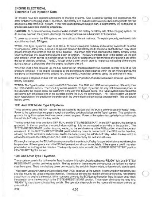
ENGINE ELECTRICALElectronic Fuel Injection DataEFI models have two separate alternators or charging systems. One is used for lighting and accessories, theother for battery charging and EFI operation. The battery size and alternator size have been designed to provideadequate output for the EFI system. If your sled is equipped with electric start, a larger battery will be required toprovide adequate cold cranking amperage.CAUTION: At no time should any accessories be added to the battery or battery side of the charging system. Todo so may overload the system, discharge the battery and cause substandard EFI operation.To power up or turn on the EFI system, we have utilized different methods. To explain properly, we have to talkabout the two basic EFI types:TYPE 1- The Type I system is used on all RXLs. To power up requires both key and auxiliary switches to be in the"Run" position. At that time, a circuit is completed between the battery positive terminal and the brown relay whichpasses through the switches and the circuit breaker. The brown relay then connects the battery directly to theECU via the fuse link, causing the ECU to begin to function. The ECU connects itself to the battery via the self - tshut-off relay, which serves to maintain power to the ECU for approximately ten minutes after power is cut off by Jthe key or auxiliary switches. The ECU is kept on for a short time in order to help prevent flooding of the <strong>engine</strong>during a restart a short time after the <strong>engine</strong> has been shut off.When the ECU is first powered up, the fuel pump will run for approximately five seconds in order to build up fuelpressure in the rail. If the <strong>engine</strong> is stopped by the switches and then restarted within the ten minute period, thefuel pump will not repeat the five second run, since the ECU was kept powered up by the self shut-off relay.If the <strong>engine</strong> is stopped or dies with the switches in the "Run" position, the ECU will remain powered up until thebattery is drained.TYPE 11- The Type II system is used on all 500 EFI models. The 1991 and 1992 models power up differently than. the 1993 and later models. The Type II system is similar to the Type I system in the way that it maintains power tothe ECU after the <strong>engine</strong> stops, but is different in the way that it powers down. The Type I system depends on theoperator to turn off at least one of the switches before the ECU will power down. The Type II system will powerdown regardless of the position of the switches in the event that the <strong>engine</strong> stops unexpectedly. This preservesbattery power.1991 And 1992 Model Type II SystemsThese systems use a "READY" light on the dash panel to indicate that the ECU is powered up and "ready" to go.Power to the system does not pass through the auxiliary switch as it does on the Type I system. This switch onlygrounds the ignition system like those on carbureted <strong>engine</strong>s. Power to the system is supplied primarily throughthe self shut-off relay and the key switch.The key switch has three positions: OFF, RUN, and SYSTEM RESET/START. In the OFF position, the ignition isgrounded. In the run position, the switch does nothing. It is not connected to any wire in this position. TheSYSTEM RESET/START position is spring loaded, so the switch returns to the RUN position when the operatorreleases it. In the SYSTEM RESET/START position battery power is connected to the ECU via the fuse link,allowing the ECU to initialize and connect itself to the battery using the self shut-off relay. When the key switch isallowed to return to the RUN position, the ECU is powered only by the self shut-off relay.If the <strong>engine</strong> is stopped the ECU will remain powered by the self shut-off relay for a period which varies with <strong>engine</strong>temperature. If the <strong>engine</strong> is warm the ECU will power down almost immediately. If the <strong>engine</strong> is cold it may staypowered up for as long as five minutes. The key only needs to be turned to the SYSTEM RESET/START positionif the "READY" light is not on.1993 And Later Type II SystemsThese systems are similar to the earlier Type II systems in function, but do not have a "READY" light or a SYSTEMRESET/START position on the key switch. The key switch on these models only grounds the ignition in order tostop the <strong>engine</strong>. There is no battery power connected to the switch in these models, unless electric start is used.This system uses and Alternator Controlled Switch (ACS) to power up the system. It is mounted on the battery boxand also houses the voltage regulator/rectifier. This device senses the rotation of the crankshaft by recognizingoutput from the <strong>engine</strong>'s alternator. It then connects power to the ECU just as the earlier Type II system does whenthe operator turns the key switch to the SYSTEM RESET/START position. This system eliminates the need for a"READY" light and a complicated key switch. The operator simply pulls on the rope and the system powers upautomatically.8/94 4.36


