You also want an ePaper? Increase the reach of your titles
YUMPU automatically turns print PDFs into web optimized ePapers that Google loves.
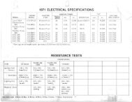
ENGINE ELECTRICALIgnition System TestingIgnition system components can be individually tested by measuring their internal resistance and insulation toground. These checks must be done with a digital volt/ohm meter. Compare the readings obtained to the valueslisted on the chart. Actual values may vary up to ± 10% between like components. Any readings outside the spanshould be considered questionable.NOTE: The stator coils can be checked without removing them from the <strong>engine</strong>. Simply disconnect the connectorplug in the stator-to-COI wire and check the resistance values between the wire colors listed below. Consult thestator schematics shown on the next pages.* Indicates a system that incorporates a white COI-to-stator ground wire. These systems will indicate continuitybetween the exciter/pulser wires and ground.EXCITER COILPULSER COILCheck Wires Value Check WiresIValueSINGLE CYLINDER MODELS BrownlWhite 123 Ohms Not Applicable19<strong>85</strong>-Current Star/Star LTto Black/RedStar Lite.TWIN CYLINDER MODELS BrownlWhite 164 Ohms Not ApplicableAll EC34-2PM (Pulseless)to Black/RedAll EC4O-PUSOPL thru 1989 BrownlWhite 164 Ohms BrownlWhite 14S0hmsAll EC44-2PM.to White to Black/RedIAll EC40PUSOPL 1990 to currentBrownlWhite 164 Ohms Not ApplicableEC4SPL (Pulseless)to Black/RedAll ECSOPM 1990 to currentAll EC44-3PM (Pulseless)/All ECSOPM thru 1989 BrownlWhite 164 Ohms BrownlWhite T 17 Ohmsto Whiteto Black/Red* Indicates a system that incorporates a white COI-to-stator ground wire. These systems will indicate continuitybetween the exciter/pulser wires and ground.cEXCITER COIL PULSER COIL CONTROL COIL TRIGGER COI LTHREE Check Value Check Value Check Value Check ValueCYLINDER Wires Wires Wires WiresMODELSAll ECS8PL-01 Black/Red 4.6 White to 100to Red Ohms White/Red OhmsAll EC60PL and Black to White 261 Red to White 20 Ohms Green to 29.4EC6SPL-01 Ohms Blue OhmsAll Black/Red to 248 Red to Green 20 Ohms White to 96 OhmsEC6SPL-02/03/0S Green Ohms White/RedAll EC7SPL-01 and Black/Red 248 Red to Green 20 White to 96 OhmsEC80PL-01 to Green Ohms Ohms White/RedThree Cylinder Models: EC58PL-01 EC60PL EC65PL EC75PL-01Secondary Ignition Coil EC65PL-01 02103/05 EC80PL-01Primary Resistance .4 Ohms .106 Ohms .4 Ohms .4 OhmsTab to Tab ± 1S% ± 1S% ± 1S% ± 1S%Secondary Resistance 4 KOhm 2KOhm 7.S K Ohm 7.S KOhmTab to Plug Wire End ± 20% ± 20% ± 20% ± 20%(Cap Removed)cSpark Plug Cap 3.7 to 6.3 3.7 to 6.3 3.7 to 6.3 3.7 to 6.3KOhm KOhm KOhm KOhmSecondary coils can also be dynamically tested with a coil power tester such as the Graham Lee Model 31 .Consult the tester operation manual for specific operating instructions.4.21 8/94 -j


