Installation Instructions - Chris Alston's Chassisworks
Installation Instructions - Chris Alston's Chassisworks Installation Instructions - Chris Alston's Chassisworks
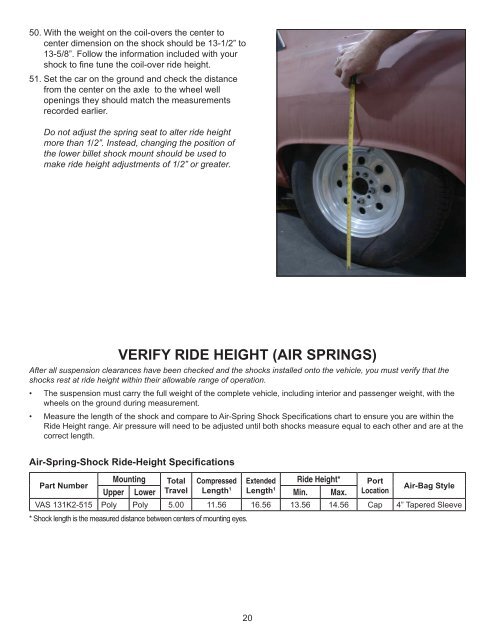
50. With the weight on the coil-overs the center tocenter dimension on the shock should be 13-1/2” to13-5/8”. Follow the information included with yourshock to fi ne tune the coil-over ride height.51. Set the car on the ground and check the distancefrom the center on the axle to the wheel wellopenings they should match the measurementsrecorded earlier.Do not adjust the spring seat to alter ride heightmore than 1/2”. Instead, changing the position ofthe lower billet shock mount should be used tomake ride height adjustments of 1/2” or greater.VERIFY RIDE HEIGHT (AIR SPRINGS)After all suspension clearances have been checked and the shocks installed onto the vehicle, you must verify that theshocks rest at ride height within their allowable range of operation.• The suspension must carry the full weight of the complete vehicle, including interior and passenger weight, with thewheels on the ground during measurement.• Measure the length of the shock and compare to Air-Spring Shock Specifi cations chart to ensure you are within theRide Height range. Air pressure will need to be adjusted until both shocks measure equal to each other and are at thecorrect length.Air-Spring-Shock Ride-Height SpecificationsMounting Total Compressed Extended Ride Height* PortPart NumberAir-Bag StyleUpper Lower Travel Length 1 Length 1 Min. Max. LocationVAS 131K2-515 Poly Poly 5.00 11.56 16.56 13.56 14.56 Cap 4” Tapered Sleeve* Shock length is the measured distance between centers of mounting eyes.20
VERIFY RIDE HEIGHT (COIL-OVERS)After all suspension clearances have been checked and the shocks installedonto the vehicle with the springs, you must verify that the shocks rest at rideheight within their allowable range of operation.• The suspension must carry the full weight of the complete vehicle,including interior and passenger weight, with the wheels on the groundduring measurement.• Measure the length of the shock and compare to Shock Specifi cationschart to ensure you are within the Ride Height range. Spring preload willneed to be adjusted at the lower spring seat until both shocks measureequal to each other and are at the correct length.• SUSPENSION MUST BE AT FULL EXTENSION AND THE VEHICLESAFELY SUPPORTED WHILE ADJUSTING THE LOWER SPRING SEAT.• With the vehicle weight carried by the suspension, it is easier to get anaccurate measurement from the bottom of the upper spring seat to thecenter of the lower mounting bolt.• DO NOT THREAD THE LOWER SPRING SEAT UPWARD MORE THAN1/2” FROM IT’S LOWEST POSITION.• If more than 1/2” of preload is needed to raise the vehicle into the correctride height range, you must step up to a heavier spring rate. Failure toincrease the spring rate will allow the spring to abruptly coil-bind before fullshock compression, limit suspension travel, and damage the shock andrelated chassis and suspension components.Bottomof UpperSpringSeat11.43” to12.46”Ride-HeightLengthCenterof MountEyeCoil-Over-Shock Ride-Height SpecificationsMountingTotal Compressed Extended Ride Height* SpringPart NumberUpper Lower Travel Length* Length* Min. Max. LengthVAS 11X11-515 COM-8 COM-8 5.15” 9.37” 14.52” 11.43” 12.46” 12”* Shock length is measured from the top of the coil spring to the top surface of the lower crossbar tab. It is easiest to measure betweenthese two points once the shock has been mounted to the vehicle.Spring Selection GuidelinesA good spring rate baseline for passenger vehicles is 200 lb./in.Differences that alter desired spring rate:Weight Reduction -50 lbsRoad Race +50 lbs (better handling)Drag Race -50 lbs (more stored energy)Spring rate effects ride quality, ride height and roll ratecharacteristics. Differences in vehicles such as aluminum enginecomponents, fi berglass body parts and chassis stiffening should betaken into consideration. Additional springs can be purchased fortuning purposes.12” VariSpringsRate(lb/in)Part Number110 VAS 21-12110130 VAS 21-12130150 VAS 21-12150175 VAS 21-12175200 VAS 21-12200250 VAS 21-12250300 VAS 21-12300350 VAS 21-12350400 VAS 21-1240021
- Page 4: 4DRIVER SIDE SHOWN
- Page 7 and 8: 3. Jack the car up and place two ja
- Page 9 and 10: 11. Bolt the upper coil-over mount
- Page 11 and 12: 18. Align the top edge on the coil-
- Page 13 and 14: 25. Remove the rear lower control a
- Page 15 and 16: Before proceeding, the rearend hous
- Page 17 and 18: 42. The upper mount and coil-over s
- Page 19: 48. Once the clearance is checked y
- Page 23 and 24: 1. Verify that the springs are supp
50. With the weight on the coil-overs the center tocenter dimension on the shock should be 13-1/2” to13-5/8”. Follow the information included with yourshock to fi ne tune the coil-over ride height.51. Set the car on the ground and check the distancefrom the center on the axle to the wheel wellopenings they should match the measurementsrecorded earlier.Do not adjust the spring seat to alter ride heightmore than 1/2”. Instead, changing the position ofthe lower billet shock mount should be used tomake ride height adjustments of 1/2” or greater.VERIFY RIDE HEIGHT (AIR SPRINGS)After all suspension clearances have been checked and the shocks installed onto the vehicle, you must verify that theshocks rest at ride height within their allowable range of operation.• The suspension must carry the full weight of the complete vehicle, including interior and passenger weight, with thewheels on the ground during measurement.• Measure the length of the shock and compare to Air-Spring Shock Specifi cations chart to ensure you are within theRide Height range. Air pressure will need to be adjusted until both shocks measure equal to each other and are at thecorrect length.Air-Spring-Shock Ride-Height SpecificationsMounting Total Compressed Extended Ride Height* PortPart NumberAir-Bag StyleUpper Lower Travel Length 1 Length 1 Min. Max. LocationVAS 131K2-515 Poly Poly 5.00 11.56 16.56 13.56 14.56 Cap 4” Tapered Sleeve* Shock length is the measured distance between centers of mounting eyes.20


