Create successful ePaper yourself
Turn your PDF publications into a flip-book with our unique Google optimized e-Paper software.
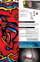
THIS INSTRUCTION BOOKLET CONTAINSIMPORTANT SAFETY INFORMATION. PLEASEREAD AND KEEP FOR FUTURE REFERENCE.This manual covers the following brands, models and model numbers:eZip Trailz: EZ-TRZ-BK, EZ-TRZ-RD-W, EZ-TRZ-BL-WeZip Skyline: EZ-SKY-SL, EZ-SKY-WH-WeZip Tri-Ride: EZ-TRIRD-SLIzip E3 Vibe: IZ-VIBE-BK, IZ-VIBE-RD-W, IZ-VIBE-BK-W, IZ-VIBE-BK-K6, IZ-VIBE-RD-W-K6Izip E3 Path: IZ-PATH-GY, IZ-PATH-BL-W, IZ-PATH-M-GY, IZ-PATH-L-GYIzip E3 Zuma: IZ-ZUMA-BL, IZ-ZUMA-RD-W, IZ-ZUMA-M-BL, IZ-ZUMA-L-BL, IZ-ZUMA-RD-WIzip E3 Metro: IZ-MET-GY, IZ-MET-GY-W, IZ-MET-M-GYBL, IZ-MET-L-GYBL, IZ-MET-GYBL-WIzip E3 Ultra: IZ-ULT-BK, IZ-ULT-M-BK, IZ-ULT-L-BK, IZ-ULT-BK-WIzip Compact: IZ-COM-WH<strong>Currie</strong> <strong>Technologies</strong>®9453 Owensmouth Avenue | Chatsworth, CA 91311Phone (818) 734-8123 | Fax (818) 734-8199www.<strong>Currie</strong>Tech.comCustomer Service (800) 377-4532Lot number ___________(Buyer to fill out)
!FULLY CHARGE BATTERIES BEFORE FIRST USE - Batteries should be fully charged immediately whenthey are received and immediately after each use for the recommended charge times (see below).• Li-Ion (Lithium Ion) batteries 4-6 hours (2-3 hours for Via Urbano)• SLA (Sealed Lead Acid) batteries 6-10 hoursWe recommend that you consult a bicycle specialist if you have doubts or concerns as to your experience or ability toproperly assembly, repair, or maintain your bicycle.Additional warning/cautions are in the assembly section of this manualWith proper care and maintenance your <strong>Currie</strong> <strong>Technologies</strong>® Hybrid Electric Bicycle will provide ease of use and be fun to ride.Below are points that will help you to maximize the enjoyment you get from your new hybrid electric bicycle.Factors To maximize the range of your hybrid electric bicycle• Rider Input - the more the rider pedals the further the distance traveled. Continuous riding, as opposed tofrequent stopping and starting, will yield the greatest range possible• Elevation Gain - the flatter the road the further the distance traveled• Weather - cold weather can adversely affect the battery capacity• Wind - traveling with a tailwind will increase distance traveled, traveling into a headwind will decrease distancetraveled• Terrain - the smoother the terrain (roadways vs. fireroads, etc.) the further the distance traveled• Rider Weight - the lighter the rider, resulting in less drain on the batteries, the further distance traveled• Bicycle Maintenance - a properly maintained bicycle will yield the greatest range possible• Tire Pressure - properly inflated tires have less rolling resistance and will be easier to pedal• Batteries - properly charged and maintained batteries will yield the greatest range possible. Batteries stored incold areas (below 50 degrees Fahrenheit / 10 degrees Celsius) will show reduced range. Batteries that have notbeen kept in optimum condition will show reduced range and run time.HELMETSSAVELIVES!!!• ALWAYS WEAR A PROPERLY FITTED HELMET WHEN YOU RIDEYOUR BICYCLE.• DO NOT RIDE AT NIGHT.• CPSC RECORDS SHOW THAT ABOUT 35% OF BICYCLERELATED DEATHS OCCUR AFTER DARK.• AVOID RIDING IN WET CONDITIONS.• CPSC RECORDS SHOW THAT ABOUT 65% OF INJURIESHAPPEN TO CHILDREN UNDER 15 YEARS OF AGE.• RIDE ONLY WITH ADULT SUPERVISIONCORRECT FITTING - MAKESURE YOUR HELMET COVERSYOUR FOREHEAD.INCORRECT FITTING. FOREHEADIS EXPOSED AND VULNERABLETO SERIOUS INJURY.2 OM 2012 Last modified May 25, 2012 2:29 PM3
Personal Care from <strong>Currie</strong> <strong>Technologies</strong>®Congratulations on your new purchase!Our Service Department is dedicated to yoursatisfaction with <strong>Currie</strong> <strong>Technologies</strong>® and itsproducts. For questions regarding performance,assembly, operation, parts or returns, contactthe experts at <strong>Currie</strong> <strong>Technologies</strong>® directly bycalling toll free1-800-377-4532Monday - Friday8:00 am - 4:00 pm (PST)The following manual is only a guide to assist you and is not a complete or comprehensive manual of all aspects ofmaintaining and repairing your bicycle. The bicycle you have purchased is a complex object. We recommend that youconsult a bicycle repair specialist if you have doubts or concerns as to your experience or ability to properly assemble,repair, or maintain your bicycle. You will save time and the inconvenience of having to go back to the store if you choose towrite or call us concerning missing parts, service questions, operating advice, and/or assembly questions.SERVICECALL TOLL FREE 1-800-377-4532Monday - Friday 8:00 a.m. to 4:00 p.m. (PST)Serial Number LocationBike Shown Upside Down####Serial NumberPLEASE DO NOT RETURNTHIS ITEM TO THE STORE.For questions or assistance on assembly contact<strong>Currie</strong> <strong>Technologies</strong>® Customer ServiceIMPORTANT – Please activate your warranty byregistering your new <strong>Currie</strong> product within 10days of purchase by visiting our web site www.currietech.com and clicking the “Register YourProduct” link.<strong>Currie</strong> <strong>Technologies</strong>®9453 Owensmouth Avenue | Chatsworth, CA 91311Phone (818) 734-8123 | Fax (818) 734-8199www.<strong>Currie</strong>Tech.comCustomer Service (800) 377-45324 OM 2012 Last modified May 25, 2012 2:29 PM5
Please Retain your Sales Receipt as Proof of Purchase.Attach receipt here.Notes: ______________________________________________________________________________________________________________________________________PART 1 Parts Identification and Tools. . . . . . . . . . . . . . . . . . . . . . . . . . . . .10-15PART 2 Before You Ride ........................................16-34PART 3 Electrical Components ..................................35-58PART 4 Assembly .............................................59-86DIRECTORY___________________________________________________________________________________________________________________________________________________________________________________________________________________________________________________________________________________________________________________________________________________________________?PART 5 Servicing ..............................................87-89PART 6 Detailed Maintenance ..................................90-115PART 7 How Things Work. ....................................116-125PART 8 Purchase Record ........................................126!Warning / Important - Take notice of this symbol throughout this manual and payparticular attention to the instructions blocked off and preceded by this symbol.6 OM 2012 Last modified May 25, 2012 2:29 PM7
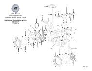
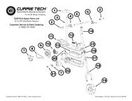
INDEXBatteryCare and information. . . . . 42-43Chargers . . . . . . . . . . . 44-48Gauge . . . . . . . . . . . . . . 35Terminal covers . . . . . . . . . 44BrakesExplanation. . . . . . . . .116-117Lever setup. . . . . . . . . . . 72Parts explosion (linear-pull) . . . 74Setup (disc, Avid BB7) . . . . 80-81Setup (disc, Tektro). . . . . . 78-79Setup (linear-pull) . . . . . . 75-77Cables & cable housing . . . . 97Care . . . . . . . . . . . . . 33-34Chain. . . . . . . . . . . 106-107ComponentsRTMB . . . . . . . . . . . . . . 10Enlightened. . . . . . . . . . . 12Folding . . . . . . . . . . . . . . 11RMB . . . . . . . . . . . . . . . 13Tricruiser . . . . . . . . . . . . . 14Crankset . . . . . . . 65, 103-105<strong>Currie</strong> DriveMaintenance . . . . . . . . . . 108FendersFront . . . . . . . . . . . . . . . 84Rear . . . . . . . . . . . . . . . 85FitFrame sizing . . . . . . . . . . . 17Riding position . . . . . . . . 18-19ForkAssembly. . . . . . . . . . . . 63Suspension. . . . . . . . 121-122Fuses . . . . . . . . . . . . . . 51Gears . . . . . . . See "Shifters","Wheels - Freewheel"HandlebarAssembly. . . . . . . . . . . 60-61Mounted components . . . . . . .See "Brakes", "Throttles", "Shifters","Power switches - Handlebar", "Battery- Gauge", "PAS", "TMM"Headset . . . . . . . . . . . . . 98Maintenance checklists . . 87-88Motor. . . . . . See "<strong>Currie</strong> Drive"PAS . . . . . . . . . . . . . . . 36Pedals . . . . . . . . . 65, 101-102Quick releasesFront Wheel . . . . . . . . . 68-69Seatpost . . . . . . . . . . . 66-67Reflectors . . . . . . . 25-26, 110Saddle . . . See "Seat & seatpost"Safety . . . . . . . . . . . . 20-29Seat & seatpostAssembly. . . . . . . . . . . 64-65Detailed maintenance . . . 99-100Quick release clamp . . See "Quickrelease"ShiftersAssembly. . . . . . . . . . . . 62Gears (how to operate). . . . 30-32Grip shifters . . . . . . . . . . . 96Shifting (how to) . . . . . . 118-119StemAssembly (quill) . . . . . . . . . 60Assembly (threadless) . . . . . . 61Maintenance . . . . . . . . . 94-95Terminology . . . . . . . . . . . 9Throttles . . . . . . . . . . . . 40Tires . . . . . See "Wheels - Tires"TMM . . . . . . . . . . . . . . . 37WheelsFront (bolt-on) installation . . 70-71Front (quick release). . See "Quickrelease - Front Wheel"Freewheel . . . . . . . . . . . 109Hub adjustament . . . . . . . . 93Maintenance . . . . . . . . . 90-93Rear (bolt-on) installation . . 70-71Rear wheel removal . . . . . . . 71Tires . . . . . . . . 91-93, 120-121Wiring diagramsRMB (2008) . . . . . . . . . . . 53RMB (2009) . . . . . . . . . . . 54RMB 2010 (with hub motor) . . . 57RTMB 2009 . . . . . . . . . . . 55RTMB 2010 (with hub motor) . . 58TMM . . . . . . . . . . . . . . . 55Via Mezza . . . . . . . . . . . . 52DerailleursPower switchesFront . . . . . . . . . . . . . . . 82 Handlebar . . . . . . . . . . . . 50 Torque requirements . . . 124-125Rear . . . . . . . . . . . . . . . 83 Standard . . . . . . . . . . . . . 49Troubleshooting . . . . . 111-1158 OM 2012 Last modified May 25, 2012 2:29 PMTERMINOLOGYPOWER SYSTEMSPAS – Pedal Assist - A sensor ring and pickup mounted near the bottom bracket allow the bicycle to sense forward pedaling andapply power. PAS+ adds a handlebar-mounted control box that allows the rider to select between different levels of assist.• Via Urbano (PAS+ only)TAG – Twist and Go - A rider-controlled system, the motor activates only when the handlebar throttle is turned.• Sereno, Tricruiser, Via MezzaPAS/TAG – Pedal Assist or Twist and Go - A handlebar-mounted button allows selection of PAS or TAG modes. PAS+/TAGreplaces the button with a handlebar-mounted control box that allows the rider to select between assist levels or switch to TAG.• Coastline, Eco Ride, Skyline, Trailz, Via Lento, Via Rapido, Zuma; E3Metro (PAS+/TAG)TMM – Torque Measurement Method - A sensor mounted in the rear dropout measures pedaling force and naturally adds motorpower in response to rider effort.• Trekking Enlightened, Urban Cruiser Enlightened, UltraBATTERY SYSTEMSRMB – Rack Mounted Battery with Sealed Lead Acid (SLA) cells - Two SLA battery packs sit vertically in the rack.• Coastline, Trailz, Via LentoRTMB – Rack Top Mounted Battery with Lithium Ion (Li Ion) cells - A single Li-Ion battery pack lies horizontally inside the rack.• Eco Ride, Via Rapido, ZumaSTB – Seat Tube Battery with Sealed Lead Acid (SLA) or Lithium Ion (Li Ion) cells - A single battery pack is mounted behind theseat tube.• Tricruiser, Via Mezza, SkylineDowntube (integrated) – Enlightened series, Lithium Ion (Li Ion) cells - A single Li Ion battery pack is hidden inside theframe's downtube• E3Metro, Trekking Enlightened, Ultra, Urban Cruiser Enlightened, Via UrbanoPART 1 - PARTS IDENTIFICATION9
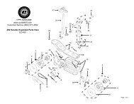
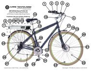
RTMB (RACK Top mounted battery) Bicycles & Standard bicycle componentsVia Rapido, ZumaElectrical components in bold textStemTop TubeSeatSeat PostSeatpost clampBatteryHead SetHead TubePower SwitchDown TubeSeat TubeShifterHandlebarThrottle (w/ PAS/TAG selector)Brake LeverBrake Control CablesFront ReflectorRear BrakeSeat StayPAS SensorFreewheel(behind chainring)Charger portRear ReflectorFront BrakeForkFront HubSpokesFolding Bicycles - Super portable, with easy folding design. Perfect for camping, fits in RV's, boats and cartrunks.Seat PostBattery PackHandlebar Quick ReleaseHandlebar HingeFrame Hinge & Quick ReleaseFront FenderBottomBracket (inside)Rear FenderRimTireChainCrank ArmHub MotorPedalHub MotorRear DerailleurChain StayTire ValveChain*To see detailed spare parts diagrams for each bicycle, please visit www.izipusa.com and click on the page corresponding toController*To see detailed spare parts diagrams for each bicycle, please visit www.izipusa.com and click10 your model.on the page corresponding to your model. See page 10 for common components.11
Enlightened Series - Lightweight, hidden, Li-Ion (Lithium Ion) battery pack in a modern designed frame.Perfect for Commuting and City RidingRMB (RACK mounted battery) bICYCLESControl BoxPAS/TAG ThrottleSealed Lead Acid BatteryCharger PortRMB rackTMM Sensor(TMM models only)Battery Pack(inside)Hub MotorController (inside)*To see detailed spare parts diagrams for each bicycle, please visit www.izipusa.com and clickPAS Sensor (behind chainring)<strong>Currie</strong> Drive Motor*To see detailed spare parts diagrams for each bicycle, please visit www.izipusa.com and click12 on the page corresponding to your model. See page 10 for common components.on the page corresponding to your model. See page 10 for common components.13
TricruiserThrottleYour new bicycle was partially assembled in the factory and then partially disassembled for shipping. Youmay have purchased the bicycle already fully assembled and ready to ride OR in the shipping carton in thepartially disassembled form. The following instructions will enable you to prepare your bicycle for years ofenjoyable cycling. For more details on inspection, lubrication, maintenance and adjustment of any area pleaserefer to the relevant sections in this manual. If you have questions about your ability to properly assemble thisunit, please consult a qualified bicycle service specialist before riding. If you need replacement parts or havequestions pertaining to assembly of your bicycle, call the service line direct at:Fender(rear)Charger portBatteryFender(front)SERVICE AND TECHNICAL SUPPORT:1 800 377 4532Monday - Friday 8:00 a.m. - 4:00 p.m. (PST)Typical Tools Required:• Phillips head screw driver• 2.5mm, 3mm, 4mm, 5mm 6mm & 8mm Allen keys• Adjustable wrench or a 8mm, 9mm, 10mm, 13mm, 14mm,15mm & 17mm open/box end wrenches• A pair of pliers with cable cutting abilityWhen working on your bicycle as instructed by thismanual, please refer to the torque values chart onpages 120-121 for detailed torque requirements. Underorover-tightened components may loosen or break,causing a fall.Controller(inside)To avoid injury, this product must be properly assembled before use. If your bicycle wasobtained assembled, we strongly recommend that you review the complete assembly! instructions and perform checks specified in this manual before riding.14 15
PART 2 - BEFORE YOU RIDEBEFORE YOU RIDEABOUT THIS MANUALIt is important for you to understand your new bicycle. By reading this manual before you go out on your first ride, you’ll knowhow to get better performance, comfort, and enjoyment from your new bicycle.It is also important that your first ride on your new bicycle is taken in a controlled environment, away from cars, obstacles, andother cyclists.GENERAL WARNINGBicycling can be a hazardous activity even under the best of circumstances. Proper maintenance of your bicycle is yourresponsibility as it helps reduce the risk of injury. This manual contains many “Warnings” and “Cautions” concerning theconsequences of failure to maintain or inspect your bicycle. Many of the warnings and cautions say “you may lose control andfall.” Because any fall can result in serious injury or even death, we do not repeat the warning of possible injury or death whereever the risk of falling is mentioned.A SPECIAL NOTE FOR PARENTSIt is a tragic fact that most bicycle accidents involve children. As a parent or guardian, you bear the responsibility for theactivities and safety of your minor child. Among these responsibilities are to make sure that the bicycle which your child isriding is properly fitted to the child; that it is in good repair and safe operating condition; that you and your child have learned,understand and obey not only the applicable local motor vehicle, bicycle, and traffic laws, but also the common sense rules ofsafe and responsible bicycling. As a parent, you should read this manual before letting your child ride the bicycle. Please makesure that your child always wears an ANSI, ASTM, SNELL approved bicycle helmet when riding.CORRECT FRAME SIZEWhen selecting a new bicycle, the correct choice of frame size is a very important safety consideration. Most full sizedbicycles come in a range of frame sizes. These sizes usually refer to the distance between the center of the bottom bracketand the top of the frame seat tube.Please note that regardless of frame size, all IZIP bicycles (excluding the Tricruiser) have a weight limit of 240lbs/109 kgincluding rider and luggage.For safe and comfortable riding there should be clearance of no less than 1 - 2 inches betweenthe groin area of the intended rider and the top tube of the bicycle frame, while the rider straddles thebicycle with both feet flat on the ground.The ideal clearance will vary between types of bicycles and rider preference. This makes straddling the frame whenoff the seat easier and safer in situations such as sudden traffic stops. Women can use a men’s style bicycle to determine thecorrect size women’s model.The following chart and diagram will help you make the correct choice. Rider leg length refers to approximate pant inseam.1-2in.!Approximate Rider LegLength61-69cm / 24-27 inches66-76cm / 26-30 inches71-79cm / 28-31 inches76-84cm / 30-33 inches79-86cm / 31-34 inchesFrame Sizing GuideSuggested Frame Size forRacing/Touring Bicycle--50cm / 19.5 inches55cm / 21.5 inches57cm / 22.5 inchesSuggested frame Size forMountain, Hybrid, Comfort,or Cruiser Bicycle37cm / 14.5 inches43cm / 17 inches45cm / 18 inches50cm / 19.5 inches52cm / 20.5 inches81-89cm / 32-35 Inches60cm / 23.5 Inches53-56cm / 21-22 Inches86-94cm / 34-37 inches63cm / 25 inches58-60cm / 23-23.5 inches16 17
Maximum Height /Minimum Insertion Mark(Should not be visible)Arms not overextendedHandlebar stemheight about thesame asseat heightPedal atbottom positionRIDING POSITIONSeat HeightIn order to obtain the most comfortable riding position and offer thebest possible pedaling efficiency, the seat height should be setcorrectly in relation to the rider’s leg length. The correct saddle heightshould not allow leg strain from over-extension, and the hips shouldnot rock from side to side when pedaling. While sitting on the bicyclewith one pedal at its lowest point, place the ball of your foot on thatpedal. The correct saddle height will allow the knee to be slightly bentin this position. If the rider then places the heel of that foot on thepedal, the leg should be almost straight.!Under no circumstances should the seat post projectfrom the frame beyond its “Minimum Insertion” or“Maximum Extension” mark. If your seat post projectsfrom the frame beyond these markings, the seat postor frame may break, which could cause you to losecontrol and fall. Prior to your first ride, be sure totighten the seat clamp properly. A loose seat clampor seat post binder can cause damage to the bicycleor can cause you to lose control and fall. Periodicallycheck to make sure that the seat clamp is properlytightened.ReachTo obtain maximum comfort, the rider should not overextend his or herreach when riding.To adjust this distance, the position of the seat can be altered inrelation to the seat post. (Refer to page 66 on how to adjust the seatclamp.)Handlebar Binder BoltHandlebar HeightMaximum comfort is usually obtained when the handlebar height isequal to or slightly higher than the height of the seat. You may wish totry different heights to find the most comfortable position.Threadless headsets and clamp-on stems are not easily adjustable. Please refer topage 61 for instructions on installation.The stem’s “Minimum Insertion” mark must not be visible above the top of theheadset. If the stem is extended beyond this mark, the stem may break or damagethe fork’s steerer tube, which could cause you to lose control and fall.Failure to properly tighten the stem binder bolt, the handlebar binder bolt, or the barend extension clamping bolts may compromise steering action, which could causeyou to lose control and fall. Place the front wheel of the bicycle between your legsand attempt to twist the handlebar/stem assembly using a reasonable amount offorce. If you can twist the stem in relation to the front wheel, turn the handlebars inrelation to the stem, or turn the bar end extensions in relation to the handlebar. Priorto riding, you must fully tighten the appropriate bolts accordingly.18 19Exceeds 2 1/2”(64mm)!Stem Wedge BoltMaximum Height/Minimum InsertionMark
USING THE BICYCLE RACKThis page intentionally left blankSafetyPlease consider the following instructions before using any luggage carrier (front or rear rack) attached to your bicycle:!• The maximum capacity of rear carrying racks on <strong>Currie</strong> products is 25kg (including any attached battery).• The maximum capacity of front racks or baskets on <strong>Currie</strong> products is 10kg.• Do not use any bicycle luggage carrier as a child seat.• Be sure the combined rider and luggage weight of your bicycle does not exceed the bicycle's weight limit.• Frequently check that all fasteners related to luggage carriers are fastened securly.• Do not modify your luggage carrier.• <strong>Currie</strong> bicycle racks are not designed to pull a trailer; do not attach a trailer to any luggage carrier.• Note that bicycle handling (steering and stopping distance) may be different when the racks are carying weight.• Ensure that any luggage is securely fitted to the bicycle rack per the manufacturer's instructions, and that nohanging straps can get caught in the wheels.• Be sure reflectors or lights attached to your bicycle are not obscured by your rack or attachments.• Distribute luggage evenly on either side of the rack for even weight balance.ATTACHMENTThe following hardware should be used to attach a rack to its respective bicycle• RMB & RTMB bicycle racks - 4x M6 x 14mm bolts, with lock washer, stainless steel. Torque to 10Nm.• Via Urbano rack - 4x M6 x 14mm bolts, with lock washer, stainless steel. Torque to 10Nm.• Skyline (optional rack) - 4x M6,14mm bolts, 2x m6 lock nuts. Stainless steel. Torque to 10Nm.• Other racks - Use included hardware, tightening attachment bolts to 10Nm.20 21
SAFETY CHECKLISTBefore every ride, it is important to carry out the following safety checks:1. Brakes• Ensure front and rear brakes work properly.• Ensure brake shoe pads are not over worn and are correctly positioned in relation to the rims.• Ensure brake control cables are lubricated, correctly adjusted and display no obvious wear.• Ensure brake control levers are lubricated and tightly secured to the handlebar.2. Wheels and Tires• Ensure tires are inflated to within the recommended limit as displayed on the tire sidewall.• Ensure tires have tread and have no bulges or excessive wear.• Ensure rims run true and have no obvious wobbles or kinks.• Ensure all wheel spokes are tight and not broken.• Check that axle nuts are tight. If your bicycle is fitted with quick release axles, make sure locking levers arecorrectly tensioned and in the closed position.3. Steering• Ensure handlebar and stem are correctly adjusted and tightened, and allow proper steering.• Ensure that the handlebars are set correctly in relation to the forks and the direction of travel.• Check that the headset locking mechanism is properly adjusted and tightened.• If the bicycle is fitted with handlebar end extensions, ensure they are properly positioned and tightened.4. Chain• Ensure chain is oiled, clean and runs smoothly.• Extra care is required in wet or dusty conditions.5. Bearings• Ensure all bearings are lubricated, run freely and display no excess movement, grinding or rattling.• Check headset, wheel bearings, pedal bearings and bottom bracket bearings.6. Cranks and Pedals• Ensure pedals are securely tightened to the cranks.• Ensure cranks are securely tightened to the axle and are not bent.7. Derailleurs• Check that front and rear mechanisms are adjusted and function properly.• Ensure shift and brake levers are attached to the handlebar, shift and brake.• Ensure derailleurs, shift levers and shift and brake cables are properly lubricated.8. Frame and Fork• Check that the frame and fork are not bent or broken.• If either are bent or broken, they should be replaced.9. Accessories• Ensure that all reflectors are properly fitted and not obscured.• Ensure all other fittings on the bike are properly and securely fastened, and functioning.• Ensure the rider is wearing a helmet.10. Motor Drive Assembly and Throttle• Ensure all motor drive components are correctly mounted and functioning properly.11. Battery Pack• Ensure the batteries are in good operation condition and kept fully charged.22 23
HelmetsIt is strongly advised that a properly fitting, ANSI or SNELL approved,bicycle safety helmet be worn at all times when riding your bicycle.The correct helmet should:- be comfortable- be lightweight- have good ventilation- fit correctly- cover foreheadReflectorsYour bicycle is supplied with one front (white), one rear (red), two wheel (white), and four pedal (orange) reflectors. Theseare an important safety and legal requirements, and should remain securely fitted and in good, clean condition at all times.Periodically inspect all reflectors, brackets and mounting hardware for signs of wear or damage. Replace immediately ifdamage is found. Some bicycles will require you to install your reflectors onto your bicycle. Please refer to the following sectionfor instructions on all the types of bicycle reflectors.Fork Mount Reflector Bracket AssemblyFirst insert one washer onto the hex bolt and insert hex bolt through the reflector bracket and thenthrough the fork. Next, insert a second washer onto the bolt and thread a hex nut onto the boltbehind the fork. Tighten bolts until snug, making sure the reflector is in an upright position. Seediagram at the right.!Always wear a properly fitted helmet which covers the forehead when riding a bicycle. Many statesrequire specific safety devices. It is your responsibility to familiarize yourself with the laws of the statewhere you ride and to comply with all applicable laws, including properly equipping yourself and yourbike as the law requires. Reflectors are important safety devices which are designed as an integral partof your bicycle. Federal regulations require every bicycle to be equipped with front, rear, wheel, andpedal reflectors. These reflectors are designed to pick up and reflect street lights and car lights in away that helps you to be seen and recognized as a moving bicyclist. Check reflectors and theirmounting brackets regularly to make sure they are clean, straight, unbroken and securely mounted.Replace damaged reflectors and straighten or tighten any that are bent or loose.Front Reflector Mount with Handlebar Bracket AssemblyFirst attach the reflector to the reflector bracket with the reflector screw, if not already done. Next,remove the clamp screw and open the reflector clamp bracket. Place reflector clamp bracket aroundthe handlebar. Tighten the clamp screw to hold reflector assembly in place. Finally, adjust thereflector assembly in place and ensure that it is upright and facing away from the bike.24 25
Seat and Handlebar Mounting ReflectorsFirst attach the reflector to the reflector bracket with the reflector screw, see the topdiagram. Next, remove the clamp screw and open the clamping reflector bracket.Place clamping reflector bracket around the handlebar or seatpost. If the clamp istoo loose, insert a rubber spear inside of the clamp. Tighten the clamp screw to holdreflector assembly in place, see the second diagram. Finally, adjust the reflectorassembly in place and ensure that it is upright and facing away from the bike.RIDING SAFELYGeneral RulesWhen riding obey the same road laws as all other road vehicles, including giving way to pedestrians, and stoppingat red lights and stop signs.For further information, contact the Road Traffic Authority, police department or Department of Motor Vehicles inyour State.Ride predictably and in a straight line. Never ride against traffic.Use correct hand signals to indicate turning or stopping.Ride defensively. To other road users, you may be hard to see.Concentrate on the path ahead. Avoid pot holes, gravel, wet road markings, oil, curbs, speed bumps, drain gratesand other obstacles.Cross train tracks at a 90 degree angle or walk your bicycle across.Expect the unexpected such as opening car doors or cars backing out of concealed driveways.Be extra careful at intersections and when preparing to pass other vehicles.Seatstay Mount Reflector Bracket AssemblyFirst insert one washer onto the hex bolt and insert hex bolt through the reflectorbracket and then through the seatstay bridge. Next, insert a second washer onto thebolt and thread a hex nut onto the bolt behind the seatstay bridge. Tighten bolts untilsnug, making sure the reflector is in an upright position. See diagram at the bottomright.Familiarize yourself with all the bicycle's features. Practice gear shifts, braking, and the use of toe clips and straps,if fitted.If you are wearing loose pants, use leg clips or elastic bands to prevent them from being caught in the chain orgears. Wear proper riding attire and avoid wearing open toe shoes.Don't carry packages or passengers that will interfere with your visibility or control of the bicycle. Don't use itemsthat may restrict your hearing.Do not lock up the brakes. When braking, always apply the rear brake first, then the front. The front brake is morepowerful and if it is not correctly applied, you may lose control and fall.Maintain a comfortable stopping distance from all other riders, vehicles and objects. Safe braking distances andforces are subject to the prevailing weather conditions.Use designated bicycle paths if possible.This bicycle is designed for on-road use only. It is not intended to be used for stunt riding, jumping, carryingpassengers, or riding off-road. If used incorrectly, the rider risks damage to components, injury, or death.26 27
Wet Weather!IT IS RECOMMENDED TO NOT RIDE IN WET WEATHER This hybrid electric bicycle is notmeant for use in the water (damp roads, puddles, rain, streams, etc.). Never immerse thisproduct in water as the electrical system may be damaged.Although the electrical components are water resistant and there is little risk of electric shock from wetweather, you should exercise caution and strongly consider not riding in such conditions, especiallyheavy rain.• In wet weather you need to take extra care.• Brake earlier, stopping distance is up to 6 times longer.• Decrease your riding speed, avoid sudden braking and take corners with additional caution.• Be more visible on the road.• Wear reflective clothing and use safety lights.• Potholes and slippery surfaces such as line markings and train tracks all become morehazardous and more difficult to see when wet.Night Riding!IT IS RECOMMENDED TO NOT RIDE AT NIGHT• Ride at night only if necessary. Slow down and use familiar roads with street lighting, if possible.• Ensure bicycle is equipped with a full set of correctly positioned and clean reflectors.• Use a properly functioning lighting set comprising of a white front lamp and a red rear lamp.• If using battery powered lights, make sure batteries are well charged.• Some rear lights available have a flashing mechanism which enhances visibility.• Wear reflective and light colored clothing.Pedaling Technique• Position the ball of your foot on the center of the pedal.• When pedaling, ensure your knees are parallel to the bicycle frame.• To absorb shock, keep your elbows slightly bent.• Learn to operate the gears properly. (Refer to pages 118-119)Hill Technique• Gear down before a climb and continue gearing down as required to maintain pedaling speed.• If you reach the lowest gear and are struggling, stand up on your pedals. You will then obtain more power fromeach pedal revolution.• On the descent, use the high gears to avoid rapid pedaling.• Do not exceed a comfortable speed; maintain control and take additional care.Cornering TechniqueBrake slightly before cornering and prepare to lean your body into the corner. Maintain the inside pedal at the 12 o'clockposition and slightly point the inside knee in the direction you are turning. Keep the other leg straight, don't pedal throughfast or tight corners. While going through the turn, keep your eyes parallel to the horizon and look as far ahead of youas possible.Please refer to pages 116-117 for braking techniques and pages 118-119 for gear shifting techniques.Rules for Children<strong>Currie</strong> products are designed for riders age 13 or older. To avoid accidents, teach children good riding skills with an emphasison safety from an early age. Children should always be supervised by an adult.1. Always wear a properly fitted helmet.2. Do not play in driveways or the road.3. Do not ride on busy streets.4. Do not ride at night.5. Obey all the traffic laws, especially stop signs and red lights.6. Be aware of other road vehicles behind and nearby.7. Before entering a street: Stop, look right, left, and right again for traffic. If there's no traffic, proceed into the roadway.8. If riding downhill, be extra careful. Slow down using the brakes and maintain control of the steering.9. Never take your hands off the handlebars, or your feet off the pedals when riding downhill.!The Consumer Protection Safety Commission advises that the riding of small wheel diameter bicycles atexcessive speeds can lead to instability and is not recommended. Children should be made aware of allpossible riding hazards and correct riding behavior before they take to the streets. Do not leave it up totrial and error.28 29
Below the Bar ShiftersMany mountain style bicycles now use a shift lever arrangementmounted on the underside of the handlebars, which use two leversoperated by the thumb and index finger. To select a lower gear push thelarger (lower) right shifter with your thumb to engage a larger rear cog.One firm push shifts the chain one cog, continuing to push will movethe chain over multiple cogs. Pulling the smaller (upper) left shifter withyour index finger moves the chain from a larger to a smaller chainwheel.To select a higher gear pull the smaller (upper) right lever with yourindex finger to engage a smaller rear cog. Pushing the larger (lower)left lever with your thumb will move the chain from a smaller to a largerchainwheel. Please refer to pages 118-119 for additional instructions in“How Things Work”.BICYCLE CARELeft hand lever Right hand leverBasic MaintenanceThe following procedures will help you maintain your hybrid electric bicycle for years of enjoyable riding.Properly maintain the batteries by keeping them fully charged when not in use.Do not ride your hybrid electrical bicycle in the water (damp roads, puddles, rain, streams, etc.) and never immerse it in wateras the electrical system may be damaged.Periodically check the wiring and connectors to ensure there is no damage and the connectors have good continuity.For painted frames, dust the surface and remove any loose dirt with a dry cloth. To clean, wipe with a damp cloth soaked ina mild detergent mixture. Dry with a cloth and polish with car or furniture wax. Use soap and water to clean plastic parts andrubber tires. Chrome plated bikes should be wiped over with a rust preventative fluid.Store your bicycle under shelter. Avoid leaving it in the rain or exposed to corrosive materials.Riding on the beach or in coastal areas exposes your bicycle to salt which is very corrosive. Wash your bicycle frequentlyand wipe or spray all unpainted parts with an anti-rust treatment. Make sure wheel rims are dry so braking performance is notaffected. After rain, dry your bicycle and apply anti-rust treatment.If the hub and bottom bracket bearings of your bicycle have been submerged in water, they should be taken out andre-greased. This will prevent accelerated bearing deterioration.If paint has become scratched or chipped to the metal, use touch up paint to prevent rust. Clear nail polish can also be used asa preventative measure.Regularly clean and lubricate all moving parts, tighten components and make adjustments as required. (Refer to Parts5 and 6 of this manual for further details).The use of alloy components and BED, SATIN and TITANIUM surface treatments minimizes the number of placeswhere rust can surface.32 33
StorageKeep your bicycle in a dry location away from the weather and the sun.Direct sunlight may cause paint to fade or rubber and plastic parts tocrack. Before storing your bicycle for a long period of time, clean andlubricate all components and wax the frame. Deflate the tires to halfpressure and hang the bicycle off the ground. Charge your batteries andmake sure they are protected from water. Batteries should be chargedevery 30 (Lithium Ion) or 90 (SLA) days to avoid capacity loss. Don't coverthe bicycle with plastic as "sweating” will result which may cause rusting.Please notice that your bicycle warranty does not cover paint damage(except as outlined in the warranty section of this manual), rust, corrosion,dry rot or theft.SecurityIt is advisable that the following steps be taken to prepare for and helpprevent possible theft.1. Maintain a record of the bicycle’s serial number, generallylocated on the frame underneath the bottom bracket or on thehead tube.2. Register the bicycle with the local police.3. Invest in a high quality bicycle lock that will resist hack sawsand bolt cutters. Always lock your bicycle to an immovableobject if it is left unattended.ELECTRONIC COMPONENTSBattery GaugeWhen the throttle or sensor is engaged (powering the motor) and thebicycle is in motion, the LEDs on the battery gauge (on the throttle orseparate unit) indicate instantaneous line voltage as measured at thebattery terminals – not the available energy in the battery pack.The line voltage willwwing out from a dead stop, or going up a steep hill,the motor will be under a high load and may show a reduced number ofLEDs or show the “Yellow” or even “Red” LED.When the throttle is disengaged (i.e. no power to the motor due tothe bicycle being stationary or coasting) the LEDs on the throttle willindicate the voltage of the battery pack. The voltage of the battery packwill rise when no load is on the motor. The best indication of how muchbattery life is remaining is to check the throttle LEDs, after reachingcruising speed, on a flat straight road as this will allow the batteryvoltage to stabilize and give a much more accurate reading.TAG Throttle withBattery GaugePAS / TAGwith Battery GaugeTMM Control Boxwith Battery GaugePART 3 - ELECTRICAL COMPONENTS3435
Pressto turn on the bicycleAfter pressing ‘Power’, all eight meter lights will flash insequence, indicating that the bike is ready to ride.If your bike has an additional physical switch or batteryselector located behind or in front of the batteries, be sureit is turned to the proper position before pressing ‘Power’.Thelights indicateremaining chargeThe battery gauge provides five indications of batterylevel.When the battery is depleted to the point of automaticshutoff, the lowest gauge light will blink indicating theneed to recharge immediately. Of course, the bicycle canstill be ridden with the system turned off.Due to the way the battery gauge measures charge, theindicator lights may fluctuate while riding based on themotor’s current load.The best indication of remaining battery life is to check thebattery level gauge LEDs after reaching cruising speedon a smooth, flat, straight road. This will allow the batteryvoltage to stabilize and will give a much more accuratereading.The button controls motorassist powerThe PAS system provides three assist levels, which youcan cycle between using the ‘Assist +/-’ button.Each level of assist corresponds to a maximum motorspeed; at level 3, the motor runs at full power. Overallrange decreases at higher power levels.The system defaults to the lowest assist level at startup.The motor will activate when the system senses the riderpedaling. It is not possible to activate the motor withoutturning the cranks.Torque MeasurementMethod36 37Pressto turn on the bicycleDo not put any pressure on the pedals when turning the bicycleon. Doing so may affect the TMM sensor calibration (the TMMsensor is re-calibrated each and every time the power is turnedon).If your bike has an additional physical switch or battery selectorlocated behind or in front of the batteries, be sure it is turned tothe proper position before pressing ‘Power’.After pressing ‘ON/OFF’, all ten meter lights will flash in sequence,indicating that the bike is ready to ride.To turn the bicycle off, hold the 'ON/OFF' button for about 3seconds.Thelights indicate remainingchargeThe battery gauge provides five indications of battery level.When the battery is depleted to the point of automatic shutoff,the lowest gauge light will blink indicating the need to rechargeimmediately. Of course, the bicycle can still be ridden with thesystem turned off.Due to the way the battery gauge measures charge, theindicator lights may fluctuate while riding based on the motor’scurrent load. This behavior does not apply to the IZIP Ultra,which uses state-of-charge (SoC) information from the batterypack to display very accurate battery charge information.The best indication of remaining battery life is to check thebattery level gauge LEDs after reaching cruising speed on asmooth, flat, straight road. This will allow the battery voltage tostabilize and will give a much more accurate reading.The and buttons control motor assistpowerThe TMM system provides five assist levels which you canchoose between using the '+’ and '-' buttons.Each increasing level of assist gives more motor power, butalso decreases overall range.The system defaults to assist level 3 at startup.The motor will activate when the system senses the riderapplying pressure to the pedals. It is not possible to activatethe motor without rider input. The 500 Watt IZIP Ultra has anadditional safety sensor that requires the bicycle to be rollingforward before the motor is activated.
Pressto turn on the bicycleAfter pressing ‘Power’, all ten meter lights will flash in sequence,indicating that the bike is ready to ride.To turn the bicycle off, hold the 'ON/OFF' button for about3 seconds.E3Ultra:Do not put any pressure on the pedals during startup.Doing so may affect the pedal-force sensor calibration (thepedal-force sensor’s zero-point is re-calibrated each andevery time the power is turned on).The BATTERY lights display remainingchargeThe meter box has five battery level indicators. The batterypack reports state-of-charge (SoC) information tothe controller and the meter box uses this information todisplay the battery level with high accuracy.When the battery is depleted to the point of automaticshutoff, the lowest gauge light will blink indicating the needto recharge immediately. Of course, the bicycle can still beridden with the system turned off.PAS Mode: the ‘-’ and ‘+’ buttons controlmotor assist powerPAS mode provides three levels of assist. You can choosebetween them by pressing the ‘+’ and ‘-’ buttons. Eachincreasing level of assist gives more motor power, butdecreases overall range. The system defaults to assistlevel 2 at startup. Regardless of the mode setting, thethrottle is always able to provide 100% power.Mode Select (green button)E3Metro:The motor will activate when the system senses the rider pedaling.It is not possible to activate the motor without turning the cranks.The throttle can act as a “boost” once the bike is rolling, but ifcrank movement is discontinued, power will drop away within 1-2seconds with or without throttle use.E3Ultra:The motor will activate when the system senses the rider applyingpressure to the cranks. It is not possible to activate the motorotherwise in PAS mode. Also the bicycle must be rolling forward atabout 3km/h before the motor will activate. This safety feature isintended to prevent unintentional acceleration.The amount of pedal pressure and the amount of motor assist are proportional;harder pedaling will result in the motor providing more assistance. The throttleacts as a “boost” once the bike is rolling, and overrides the pedal sensor whenapplied.TAG ModeIn TAG mode, the pedal sensor (E3Metro) or pressure sensor (E3Ultra) used forPAS mode operation is disabled, and the bike responds only to throttle input. Justtwist the throttle to apply 0-100% of motor power. The ‘-’ and ‘+’ buttons are notused in this mode.38 39
PAS SensorRingTAG ThrottleThrottlesThrottles are equipped on some models of electric bicycles. Throttlesoperate by rotating the throttle towards the rider much like a motorcycle.They generally are the inner half of the right side handlebar grip andmay also contain a battery gauge. The more you twist the throttle, thefaster the motor system will propel the bicycle.TAG (Twist and Go)Before you begin riding, turn the main power switch on, then startriding as you would ride any regular, non motor assisted bicycle. Afteryou have begun to ride, slowly twist the throttle (on equipped models)towards you. The more you twist the throttle, the more motor powerwill be applied to the wheels. You may feel the pedals get a “lighter”feel than when riding without the motor assisting you. Once you havetwisted the throttle all the way, the motor will accelerate you to its fullspeed of about 18-20mph (28-32 km/h).Press ON/OFF to turn on the bicycleThe battery gauge lights will illuminate, indicating that the bike is ready to ride. Forsome models the ON/OFF is on the battery (see battery section of manual)The gauge lights indicate remaining chargeThe battery gauge provides three indications of battery level. Because the gaugesimply measures the voltage of the battery pack, it may fluctuate under load (like whenriding up a hill).The PAS/TAG switch changes between “Pedal Assist” and“Twist and Go” power modes.In Pedal Assist mode, the motor will automatically run at 50% power while the rider ispedaling. The throttle acts as a “boost” in this mode, allowing the rider to control up to100% of the motor’s power. The throttle is only active while the pedals are turning.PAS (Pedal Assist)Electric bicycles with this system have a throttle that is only active whenthe pedals are in a forward motion. A sensor ring on the bottom bracketspindle rotates and a sensor reads this rotation.Twist and Go is a simple throttle-only mode. Just twist the throttle toward youto apply 0-100% of the motor’s power. In this mode, the pedal assist sensor isnot enabled, and the motor will not activate unless the throttle is twisted.Begin by first riding as if you are on a normal non-electric bicycle. After afew seconds, the motor will slowly activate and ramp up to 50% power.Then, while the pedals are in motion, you can slowly twist the throttletowards you to activate the full motor power.Power and PAS / TAG selector toggle switch. Forsome models the ON/OFF is on the battery or rack(see battery section of manual)PAS / TAG throttle switchThe type of system enables the rider to select between the PAS andTAG modes via the toggle switch (left in = PAS, right in = TAG).Note: When using the TAG mode you will use more battery power andthus shorten range of the bicycle.40 41
Battery Care and InformationProper maintenance of batteries will maximize their lifespan and capacity. <strong>Currie</strong> <strong>Technologies</strong>® warranties your newbatteries from the date of purchase only if properly cared for—refer to the limited warranty for details.<strong>Currie</strong> uses SLA (Sealed Lead Acid) or Li-Ion (Lithium Ion) batteries in all of our hybrid electric bicycles and scooters.These are both very user-friendly types of batteries when cared for properly.CareEven with proper care, rechargeable batteries do not last forever. Every time the battery is discharged and subsequentlyrecharged, its relative capacity decreases by a small percentage. You can maximize the life of your battery by following theinstructions in this guide.• Batteries should be fully charged immediately when they are received for the full recommended charge times.SLA recommended charge time: 6-10 hours (depending on model)Li-Ion recommended charge time: 4-6 hours (2-3 hours for Via Urbano). For a complete, 100% charge, leavethe battery on the charger for one full hour after the charger indicator light turns green.• Never charge batteries for longer than 24 hours.• SLA and Li-Ion batteries do not have a “memory.” Partial discharge/charge cycles will not harm the batteries’ capacity orperformance.• The rated output capacity of a battery is measured at 77°F (25°C). Any variation in this temperature will alter theperformance of the battery, and shorten its expected life. High temperatures especially reduce overall battery life & runtime.• <strong>Currie</strong> bikes and scooters are equipped with a five-minute sleep function. If no activity is detected after five minutes,the bike/scooter will go into “stasis” mode to conserve battery power. Simply cycle the bike/scooter off then on again tore-activate the battery.• Always be sure to turn the bike/scooter power switch to “OFF” after each use. If you leave the power switch in the “ON”position, or your product has not been charged for a long period of time, the batteries may reach a stage at which they willno longer hold a charge.• Be friendly to the environment! Be sure to recycle your old batteries at a local battery-recycling center. Do not throw themin the garbage! Check www.call2recycle.org for more information on free battery dropoff locations.StorageWhen storing your batteries for a long period of time (longer than two months):• Charge your batteries every 90 days to avoid capacity loss. Batteries slowly self-discharge when left unused for along period of time; if the battery cells are allowed to reach a critically low voltage, their lifespan and capacity will bepermanently reduced.• Always disconnect your charger from the wall outlet and battery before storing the battery.• Avoid storing your batteries in extreme temperatures, whether hot or cold.• Batteries are best kept in a cool, dry place. Do not allow batteries to accumulate condensation, as this could causeshorting or corrosion.• The recommended storage temperature for both SLA and Li-Ion batteries is between 32-77 °F (0-25°C).• Avoid exposing the battery to extreme heat (104°F or higher) for long periods of time.FAQQ: Do I need to “break-in” my batteries?A: Yes, it is recommended that you perform a “break-in” cycle consisting of ~ three discharge/charge cycles to allow yourbatteries to reach optimum performance. This involves three complete discharges and three complete recharges. After thisinitial “break-in” cycle the batteries will have maximum possible performance and less line voltage fluctuations under load.Q: Is it normal that the batteries get warm when recharging?A: Yes, it is normal that the batteries will become warm to the touch during the recharging process. This is because theincrease of internal resistance and less energy conversion efficiency from electric energy to chemical energy.Q: How long will my batteries last before needing replacement?A: Average battery life depends on use and conditions. Even with proper care, rechargeable batteries do not last forever.Conservatively, an SLA battery will come to the end of its useful life after ~200 full discharge/charge cycles, while Li-Ionbatteries will last about 500 cycles. A partial charge/discharge counts fractionally against those numbers; running thebattery down halfway then recharging it completely uses up one half of a charge cycle.“End of useful life” refers to the point at which a battery can no longer supply 80% of its original rated capacity in amperehours.After this point, the aging process will accelerate and the battery will need to be replaced.42 43
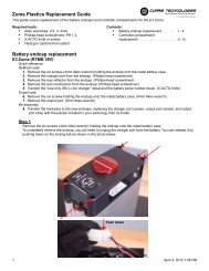
Battery Terminal CoversBicycles with Rack Mounted Batteries are equipped with battery terminal cover(s)(see photo). These protect the battery terminals from debris and water when theterminal is not in use (i.e. when the battery is removed from the bike).These battery terminal covers need to be removed in order for the battery to makecontact with terminals.ChargerThe hybrid electric bicycle comes with its own "Smart Charger” that connects with an easy-access charger port for recharging thebatteries. This charger unit has lights that show the battery charge status. Refer to the instructions that appear on the chargerunit and its instructions.Batteries work best when they have a full charge, so always be sure to recharge them fully after each ride. If you leave them in arun-down condition, without recharging them, it will shorten their life expectancy.FCC instructionsFCC Warning for the battery chargerWarning: Changes or modifications to the charger not expressly approved by the party responsible for compliance could void theuser’s authority to operate the equipment.NOTE: This equipment has been tested and found to comply with the limits for a Class B digital device, pursuant to Part 15 of theFCC Rules. These limits are designed to provide reasonable protection against harmful interference in a residential installation.This equipment generates, uses and can radiate radio frequency energy and, if not installed and used in accordance with theinstructions, may cause harmful interference to radio communications. However, there is no guarantee that interference will notoccur in a particular installation. If this equipment does cause harmful interference to radio or television reception, which can bedetermined by turning the equipment off and on, the user is encouraged to try to correct the interference by one or more of thefollowing measures:* Reorient or relocate the receiving antenna.* Increase the separation between the equipment and receiver.* Connect the equipment into an outlet on a circuit different from that to which the receiver is connected.* Consult the dealer or an experienced radio/TV technician for help.• Li-Ion (Lithium Ion) batteries - charge for 4-6 hours for full charge• SLA (Sealed Lead Acid) batteries - charge for 6-10 hours for full chargeThe charger may get warm to the touch, so make sure you charge them in an open area and do not lay anything on the chargerunit while charging. Although you cannot over-charge the batteries using the <strong>Currie</strong> “Smart Charger”, we recommend that you donot leave the charger plugged in for more than 24 hours.If your charger shows a solid green light after charging for a short period of time, your battery may have been only partially discharged(short ride), or this may be the sign of a partially worn out battery with reduced storage capacity. Continue charging forthe full time, to cover all the bases. If the battery still has not charged, you may need to replace it.Even with proper care, a rechargeable battery does not last forever. Average battery life depends on use and conditions.The charger and charger port should be regularly inspected for damage (cord, plug, enclosure, etc.).If damage is found stop using the affected part until the it can be repaired or replaced.44 45!
How to use the SLA Chargers (standard)1. Plug the charger into the outlet. The indicator light on the top of the chargerwill illuminate when the charger is working properly. Refer to the sticker on thecharger for actual status light indication.142. Insert the plug (XLR, 2v1h, DC, or 2 3v) 3 into the charger port on the bike beingsure the charger plug is fully seated in the charger port. The light should besolid red or blinking green to indicate charging however you will need to referto the sticker on the charger for actual status light indication, as there aredifferent chargers for different battery chemistries.143. Once the battery reaches full charge, the light will return to solid green2 3however you will need to refer to the sticker on the charger for actual statuslight indication.4. When charging is complete, unplug the charger from the wall before removingit from 1 the charger port.4Example of SLACharger w/ XLR PlugHow to use the Li-Ion ChargersBefore using the charger locate the voltage selector switch (Li-Ion chargers only) on the back of the charger.Select either 115 Volts or 230 Volts depending on the country you reside in. Using the wrong voltage setting willpermanently damage the charger and/or electrical components on the hybrid electric bicycle.1. Select the proper voltage for your country• 115V for North American• 230V for most of Asia and Europe2. Be sure the charger’s power switch is turned “OFF” (redlight should be off) front and rear views below2 3Charge for the full time. If the battery still has not charged, you may need to replace it.XLR3 Plug2v1h Plug3v Plug1122 3344XLR4 Plug(36 volt systems)DC Plug(male and female)Voltage SelectorSwitch1. Connect power cord to charger then plug powercord into wall outletPower Switch - turnto “OFF” positionRed lightshould be“OFF”!Use only <strong>Currie</strong> Authorized SLA chargers with bicycles equipped with SLA batteries.Using any other charger will damage the batteries and void your warranty.46 47
3. Plug charger into 24V battery charger port5. The red light should come on indicating the charger haspower. The orange light should then come on indicatingthat the charger is charging the battery. When the lightchanges from orange to green the battery is full and thecharger has completed charging the battery.Main Power SwitchesStandard Power SwitchesThe power switch may be located, depending on the model ofbike, in the following locationsEnlightened TMMBike4. Turn the charger’s power switch “ON”RTMB BikeRed light shouldturn “ON” first• On the battery pack itself (STB Series)• On the back side of the rack behind the rear reflector(RMB Series 2008+)• On the front side of the rack, directly beneath andbehind the saddle (RTMB 2009)• On the controller box (Via Urbano, RTMB 2010)Be sure to turn the switch off whenever you are not using thebicycle or when charging the bicycle.STB Bicycles RMB Bicycles (2008+)Orange lightshould turn“ON” whilechargingRTMB Bicycles (2009+)Via Urbano!Power Switch - turnto “ON” position* If the orange light flashes when the charger is pluggedinto the battery, the charger does not recognise yourbattery. Please contact Customer Service for helpresolving this issue.Use only <strong>Currie</strong> Authorized Li-Ion chargers with bicycles equipped with Li-Ion batteries.Using any other charger will damage the batteries and void your warranty.Three-Position Power SwitchesBikes with dual rack mounted battery packs (RMB) areequipped with a three-position power switch. This switch hastwo "ON" positions that correspond to the two battery packs.The switch is "OFF" when placed at the center position.OnOn(Left pack)Off(Right pack)Three-Position PowerSwitch48 49
Handlebar Power ButtonsSome 2010 RMB and TMM models feature a handlebar-mountedpower button, either on the control box or as a separate twobuttoncontrol next to the throttle.On TMM bicycles this handlebar button is the sole means ofturning the electrical system on and off; there is no other powerswitch.RMB bicycles with handlebar-mounted power buttons use atwo-position battery selector switch as described in the followingsection, in addition to the handlebar-mounted controls.Two-Position Power SwitchesRMB bicycles with handlebar mounted power buttons use atwo-position ON/ON switch, located behind the rear reflector onthe backside of the rack. The left or right switch position selectsa corresponding battery, and does not need to be changed againunless a different battery source is desired.Handlebar Power Button(RMB & RTMB 2010)Control Box Power Button(TMM)Control Box Power Button(RMB)FusesAll <strong>Currie</strong> <strong>Technologies</strong>® Hybrid Electric Bicycles are equippedwith fuses. The fuse may be located, depending on the model ofbike, in the following locations• CX Series (40A glass type fuse) - On the battery pack,externally accessible• RMB Series (40A glass type fuse) - On the backside of thebattery pack, externally accessible• STB Series (24V, 40A glass type fuse) - Inside the battery,must open the battery pack to access• STB Series 2011+ (24V, 40A glass type fuse) - On thebattery pack, externally accessible• STB Series (36V, 40A glass type fuse) - On the batterypack, externally accessible• Enlightened Series (Li-Ion, 30A blade type fuse & 5A bladetype fuse) - inside the bottom end of the downtube, removedowntube cap to accessIn the event of an overload the fuse will pop and need to bereplaced. In this instance replace only with an approved part from<strong>Currie</strong> <strong>Technologies</strong>®CX BicyclesSTB Bicycles (36V)RMB Bicycles (2007, 2008)STB Bicycles (24V)Key Lock Power SwitchesCertain models (ex. HG1000, Tricruiser) are equipped with a keylock power switch. This feature provides added security allowingonly the person with the key to turn the power on or off. This keylock switch has the same function as a standard power switch.Two Position Power SwitchKey Lock Power SwitchRisk of fire. Do not bypass fuse.50 51!STB Bicycles (24V) 2011Enlightened Series (Li-Ion)
FULLHALFLOWLEN123Wiring Diagram - Via Mezza (TAG system) w/ STB Bicycles(Diagram is for representational purpose only. Your bicycle's wiring system may differ)BRAKE LEVER, RIGHTBRAKE LEVER, LEFTWiring Diagram - TAG/PAS w/ RMB Bicycles (2008)(Diagram is for representational purpose only. Your bicycle's wiring system may differ)THROTTLETHROTTLEASSIST CONVERTER(a.k.a. “WHITE BOX”)BATTERY CASE (Complete)BATTERY CASE (Complete)1:1 ASSIST SENSOR(a.k.a. “BLACK BOX”)SWITCHWIRE HARNESS, BATTERY CASECONTROLLERCONNECTOR IN USEWIRE HARNESS,ADAPTER (DM-E-250C)WIRE HARNESS, BATTERY PORTONOFFFUSECONTROLLERBRAKE LEVER, LEFTSecondardy Battery Box(optional)BATTERY PORTCHARGER PORTFUSEBATTERYBATTERYBATTERYWIRE HARNESS, BATTERY PORTBATTERYMOTORWHEEL, REAR W/ HUB MOTORWIRE HARNESS, SWITCHBATTERY PORTSWITCHWIRE HARNESS, BATTERY PORTVia Mezza (STB w/ SLA Batteries) Bikes (2008 USA) WIRING DIAGRAMRack Mount Battery (RMB w/ SLA Batteries) Bikes (2008 USA) WIRING DIAGRAM52 For updated and new wiring diagrams, please visit www.currietech.com or call our customer service line at 1-800-377-4532For updated and new wiring diagrams, please visit www.currietech.com or call our customer service line at 1-800-377-453253
fullhalfemptyTAG / PAS123530231Wiring Diagram - TAG/PAS w/ RMB Bicycles (2009+)(Diagram is for representational purpose only. Your bicycle's wiring system may differ)THROTTLEWiring Diagram - TMM Bicycles(Diagram is for representational purpose only. Your bicycle's wiring system may differ)CADENCE SENSORBRAKE LEVER(RIGHT) -- for european productionCONTROLLERBATTERY CASE (Complete)BRAKE LEVER(LEFT)WIRE HARNESS, BATTERY CASECHARGER PORTWHEEL (w/ HUB MOTOR)BATTERYCHARGER PORTCONTROLLERBRAKE LEVER, LEFTSecondardy Battery Box(optional)BATTERY TERMINALPROGRAMMING PORTFUSEBATTERYBATTERYTMM SERVICE PORTTMM4 SENSORWIRE HARNESS, BATTERY TERMINALMOTORWIRE HARNESS, SWITCHBATTERY TERMINALTMM METER BOXSWITCHWIRE HARNESS, BATTERY TERMINAL54 For updated and new wiring diagrams, please visit www.currietech.com or call our customer service Rack Mount line Battery 1-800-377-4532(RMB w/ Controller-n-White Box, SLA Batteries) Bikes (2009 USA) WIRING DIAGRAMFor updated and new wiring diagrams, please visit www.currietech.com or call our customer service line at 1-800-377-453255Bikes with serial numbers that start with “DM”ENLIGHTENED TMM WIRING DIAGRAM, rev3
3052 13123Wiring Diagram - Rack Top Mount Battery (RTMB 2009)(Diagram is for representational purpose only. Your bicycle's wiring system may differ)Wiring Diagram - TAG/PAS w/ RMB Bicycles (2010+) with hub motor(Diagram is for representational purpose only. Your bicycle's wiring system may differ)CADENCE SENSORTHROTTLEBATTERY CASE (Complete)WHEEL (w/ BRUSHLESS HUB MOTOR)JUNCTION BOXWIRE HARNESSWIRE HARNESS, BATTERY CASECHARGER PORTTHROTTLECADENCE SENSORNote - PAS/TAG switch connection whichis not used on the RTMB bikesNote - TAG jumper, for system testing only.This item is not included with bike, available as part ofservice kit (part # TL-WR-007)BATTERY (RTMB)FULLHALFLOWBATTERY TERMINALCONTROLLERHANDLEBAR CONTROLSSWITCHFUSEBATTERYBATTERYONOFFPASTAGBRAKE LEVER(LEFT)BATTERY TERMINALSecondardy Battery Box(optional)BRAKE LEVER, LEFTMOTORNote - early USA production has only onebrake inhibitor connector. Can upgrade todual inhibitor via “Y” adapterBATTERY TERMINALCONTROLLERBRAKE LEVER, RightWIRE HARNESS, SWITCHSWITCHBRAKE LEVER(RIGHT) -- for european productionWIRE HARNESS, BATTERY TERMINALRack Top Mount Battery (RTMB w/ Li-Ion Batteries) Bikes (2009 USA) WIRING DIAGRAMBikes with serial numbers that start with “DM”56 For updated and new wiring diagrams, please visit www.currietech.com or call our customer service line at 1-800-377-4532 For updated and new wiring diagrams, please visit www.currietech.com or call our customer service line at 1-800-377-453257
231530Wiring Diagram - Rack Top Mount Battery (RTMB) 2010+ with hub motor(Diagram is for representational purpose only. Your bicycle's wiring system may differ)WHEEL (w/ BRUSHLESS HUB MOTOR)CADENCE SENSORJUNCTION BOXWIRE HARNESSFULLHALFLOWTHROTTLEHANDLEBAR CONTROLSONOFFPASTAGBRAKE LEVER, LEFTBicycle AssemblyAssembly GuidesIndividual assembly guides for each bicycle model can be found packaged with your bicycle, or viewed online by visitingwww.currietech.com and clicking on the page for your model.Getting StartedOpen the carton from the top and remove the bicycle. Remove thestraps and protective wrapping from the bicycle. Inspect the bicycleand all accessories and parts for possible shortages. It is recommendedthat the threads and all moving parts in the parts package be lubricatedprior to installation. Do not discard packing materials until assemblyis complete to insure that no required parts are accidentallydiscarded. Note: Your bicycle may be equipped with different stylecomponents than the ones illustrated.PART 4 - ASSEMBLYBATTERY (RTMB)CONTROLLERBRAKE LEVER, RightBATTERY TERMINAL!We recommend that you consult a bicyclespecialist if you have doubts or concernsas to your experience or ability to properlyassembly, repair, or maintain your bicycle.58For updated and new wiring diagrams, please visit www.currietech.com or call our customer service line at 1-800-377-453259
Stem BoltTop NutWedgeBinder BoltMinimum InsertionMarkHead TubeStem and Handlebars (Standard Quill-type)Most <strong>Currie</strong> bicycles use this stem type1. Remove the protective shipping cap from the stem wedge.2. Remove the Stem Plug from the stem. Loosen the Stem Bolt with a6mm allen wrench or 13mm box wrench.3. Insert the stem into the headtube of the bicycle. Ensure that theMinimum Insertion Line is below the top nut of the headset.4. Align the stem and handlebar so it is in line with the front wheel.5. Tighten the Stem Bolt with the 6mm allen wrench. Reinsert the StemPlug into the stem.6. Check the headset for smooth rotation and that the top nut is securedtightly.7. Loosen the 6mm Binder Bolt and rotate the handlebar so the levers areat a 45 degree angle below the handlebar.8. Retighten the Binder Bolt to ensure the handlebar does not rotate inthe stem.WARNING: MINIMUM INSERTION LINE MUST BE HIDDEN WITHIN THEHEADTUBE OF THE BICYCLE.!If the stem is not inserted into the top nut to at least the“Minimum Insertion” mark, it is possible to over-tightenthe stem bolt and damage the fork steerer tube. If theseinstructions are not followed, it could cause an unsafecondition and risk injury to the rider. Check steering tightnessprior to riding by straddling the front wheel. Try turning thehandlebar. If you can turn it without turning the front wheel,the stem is too loose. Re-align the handlebar with the frontwheel and re-tighten the stem bolt.NOTE: Some models of bicycles may be equipped with a stem that hasan adjustable angle. In addition to the normal assembly, these stems willrequire angling the stem to the desired position, and securely tighteningthe 6mm Allen bolt located underneath the stem. Failure to do thismay cause loss of steering control.Stem and Handlebars(Threadless/Aheadset)Stem Installation (Should be assembled on thebike already)1. Insert the compression bolt through the topcap and the stem. Begin threading into thestar nut.2. Tighten compression bolt so it removes allplay from the fork, but allows the fork to rotatesmoothly.3. Align the stem with the front wheel. Tightenthe stem clamp bolts to secure the stem to thesteerer tube.Handlebar Installation1. Remove the stem cap bolts and stem cap.2. Insert handlebar into the stem cap.3. Tighten the stem cap bolts equally. Note thedistance between the stem and stem cap "A"should be equal on the top and bottom of thestem cap.60 61InstalledbyfactoryStem Clamp BoltsCompression BoltTop CapSpacerBearing RaceBearing RetainerUpper Headset CupBearing RetainerForkSteerer TubeHeadset WedgeBearing Dust CoverStar Nut(Inside Steerer Tube)HeadtubeLower Headset CupBearing Dust CoverHeadset Crown RaceHandlebarStem CapBoltsStem Cap
Brake lever binder bolt (tighten from top side)(5mm Allen key)ShiftersTighten the bolts that clamp the shifters and brakelevers to the handlebar using a 5mm Allen key orPhillips head screwdriver. This step is completed at thefactory, but it should be checked before operating yourbicycle.(Figure 1) Handlebar with Grip Shifter.(Figure 2) Top mounted thumb shifter.CrownSteerer TubeBrake BossDrop-outForksThere are two different types of forks that vary in styles anddimensions. One type is a rigid fork (Figure 1) consisting of stationarytubing with curved blades. The other type is asuspension fork (Figure 2) consisting of inner stanchion tubesriding on elastomers or springs inside of a straight outer forkleg. This mechanism acts as a shock absorber with a specifiedamount of travel that varies between models. Some suspensionforks are not adjustable and are very difficult to disassemble. Ifservice is needed on a suspension fork, consult a professionalbicycle repair technician.1.Shifter binder bolt(2.5mm Allen key)1.Blade!Do not attempt to disassemble a suspension forkyourself. Consult a professional bicycle repairtechnician.Shifter binder bolt(4mm Allen key)CrownBrake BridgeBrake BossDrop-outIf your bike is equipped with a suspension fork, check that thefork compresses and rebounds smoothly. To do this, place thefork dropouts against the ground, push and release the handlebar.The fork will generally compress 1-2” and rebound quickly.Most elastomer type forks will gradually soften with use.2.Steerer Tube!Failure to properly tighten clamping bolts may cause suddenmovement of the component resulting in loss of steering control.62 632.Fork Blade
Standard Seat PostSeat and Seat PostYour bicycle may come equipped with either astandard or a micro-adjustable seatpost.Standard SeatpostAttach the seat to the seat post by first looseningthe nuts on the seat clamp. Insert the tapered endof the seat post into the seat clamp until it is at thetop of the clamp. Partially tighten the nuts on theseat clamp, then insert the seat assembly into theframe of the bicycle and adjust the seat to the properheight. The seat post must be inserted to at leastthe “Minimum Insertion” line. Move the quick releaselever to the closed position. You should feel considerable resistance while moving the lever. If not, re-open and tighten thelever, then move it to the closed position. See the section in this manual regarding quick releases for more detailed instructions.Adjust the seat to be centered in the clamp and generally level with the ground, then re-tighten the clamp nuts evenly beforeriding. Avoid riding the bike with a loose saddle.Micro-Adjustable SeatpostLoosen the seat fixing bolt, then slide the seat into the clamp. The two seat rails should fit into the corresponding channelsin the clamp. There is usually no need to completely remove the fixing bolt, but it may be necessary in some cases. Partiallytighten the seat fixing bolt, then insert the seat assembly into the frame of the bicycle and adjust the seat to the proper height.The seat post must be inserted to at least the “Minimum Insertion” line. Move the quick release lever to the closed position.You should feel considerable resistance while moving the lever. If not, re-open and tighten the lever, then move it to the closedposition. See the section in this manual regarding quick releases for more detailed instructions. Adjust the seat to be centeredin the clamp and generally level with the ground, then re-tighten the seat fixing bolt before riding. Avoid riding the bike with aloose saddle.NOTE: Some models of bicycles may be equipped with a suspension seat post (See diagram on next page). Some suspensionposts can be adjusted for stiffness using the preload adjusting screw. Turning the 6mm Allen screw Clockwise will make thesuspension stiffer, while turning the 6mm Allen screw Counter-clockwise will make the suspension softer.!Seat Clamp NutsSeat Fixing BoltQuick Release lever(same on both seatpost types)Micro-AdjustableSeat PostThe seat post must be inserted so that the minimum insertion mark cannot be seen. Thequick release mechanism must be tightened securely to prevent a sudden shift of theseat when riding. Failure to do this may cause loss of bicycle control.Suspension SeatpostPedals & Crank SetLook for the letters “R” for right, and “L” for left, stamped on each pedalspindle. Start threading each pedal by hand to avoid stripping the threads.Tighten with a 15mm narrow open ended wrench. Note that the righthand pedal attaches to the chainwheel side crank arm with a right-hand(clockwise) thread. The left pedal attaches to the other crank arm and hasa left-hand (counter-clockwise) thread. It is very important that you checkthe crank set for correct adjustment and tightness before riding yourbicycle. New cranks may become loose with initial use, refer to pages 107-109 for proper crank set adjustment and maintenance. Once the pedalshave been installed, remove the dust caps from the center of each crankarm. Tighten the spindle nuts securely (approx. 350 in. lbs.) with a 14mmsocket wrench or an 8mm Allen wrench, depending on style, then replacethe dust caps.Attachment of an incorrect pedal into a crank arm canstrip pedal threads and cause irreparable damage. Beforeyour first ride, please check to insure your pedals areattached correctly.64 65AttachSeat HereDustCapBootMinimumInsertionMarkPreload adjustingscrew on underside!Proper Seat PositionSeat is level with groundand centered in clamp
Seat Post Clamp - Quick ReleaseMany IZIP and eZip bicycle models use quick release (QR) levers to facilitate common tasks such as frontwheel removal and seat height adjustment. When properly adjusted, quick release levers are both safe andconvenient, but you must understand and apply the correct technique to adjust them properly before riding yourbicycle to prevent serious injury or death from a fall.aTension adjustingnutbQuick release levers use a cam action to clamp the wheel or other components in place. Because of theiradjustable nature, it is critical that you understand how they work, how to use them properly, and how much forceyou need to apply to secure them.Warning: The full force of the cam action is needed to clamp the wheel securely. Holding the nut with one handand turning the lever like a wing nut is NOT a safe or effective way to close a quick release and will not clamp thewheel or other components safely.openClosedQUICK RELEASE USAGERiding with an improperly adjusted wheel quick release can allow the wheel to wobble or fall off the bicycle,which can cause serious injury or death. Therefore, it is essential that you:1. Ask your dealer or a local bike shop to help you make sure you know how to install and remove yourwheels safely.2. Understand and apply the correct technique for clamping your wheel in place with a quick release.3. Each time, before you ride the bike, check that the wheel is securely clamped.Adjusting a quick release seatpost clampIn a seatpost quick release system, the seatpost is clamped in place by the force of the quick release campushing against one side of the clamp and pulling the tension adjusting nut, by way of the skewer, against theother. The amount of clamping force is controlled by the tension adjusting nut. Turning the tension adjusting nutclockwise while keeping the cam lever from rotating increases clamping force; turning it counterclockwise whilekeeping the cam lever from rotating reduces clamping force. Less than half a turn of the tension adjusting nut canmake the difference between safe clamping force and unsafe clamping force.1. With the quick release clamp in the OPEN position, insert the seatpost, with saddle attached, into thebicycle’s seat tube.2. Swing the quick release lever into the CLOSED position.3. Grab the saddle with both hands and attempt to rotate it (and thus rotate the seatpost in the seat tube).4. If you are able to force the seatpost out of alignment with the frame, the seatpost clamp needs to be adjusted.Holding the quick release lever in the OPEN position with one hand, tighten the tension adjusting nut withyour other hand about 1/2 turn clockwise.5. Attempt to swing the lever into the CLOSED position. If the lever cannot be pushed all the way to theCLOSED position (figure b), return the lever to the OPEN position, then turn the tension adjusting nutcounterclockwise one-quarter turn and try tightening the lever again. Repeat steps 3, 4 & 5 until proper quickrelease tension is achieved.66 67
Front Wheel - Quick ReleaseInstalling a quick release front wheelIn a quick release system, the wheel hub is clamped in place by the force of the quick release cam pushingagainst one dropout and pulling the tension adjusting nut, by way of the skewer, against the other dropout.The amount of clamping force is controlled by the tension adjusting nut. Turning the tension adjusting nutclockwise while keeping the cam lever from rotating increases clamping force; turning it counterclockwisewhile keeping the cam lever from rotating reduces clamping force. Less than half a turn of the tensionadjusting nut can make the difference between safe clamping force and unsafe clamping force.1. Remove the tension adjusting nut and one of the small springs, then slide the quick release skewer throughthe hub. If your bicycle has a disc brake, insert the skewer starting on the side with the brake rotor. Replacethe spring and tension adjusting nut (fig a).2. If your bicycle has rim brakes, disengage them to increase the clearance between the tire and brake pads.3. Install the wheel into the dropouts, making sure the quick release lever is on the left side of the bicycle.aTensionadjusting nutbSpringsWARNING: Securely clamping the wheel takes considerableforce. If you can fully close the quick release without wrappingyour fingers around the fork blade for leverage, and thelever does not leave a clear imprint in the palm of your hand,the tension is insufficient. Open the lever; turn the tensionadjusting nut clockwise a quarter turn; then try again.6. If the lever cannot be pushed all the way to a position parallel tothe fork blade, return the lever to the OPEN position. Then turn thetension adjusting nut counterclockwise one-quarter turn and trytightening the lever again.7. Re-engage the brake to restore correct brake pad-to-rim clearance;spin the wheel to make sure that it is centered in the frame andclears the brake pads; then squeeze the brake lever and make surethat the brakes are operating correctly.4. Holding the quick release lever in the OPEN position with one hand, tighten the tension adjusting nut withyour other hand until it is finger tight against the fork dropout.5. While pushing the wheel firmly to the top of the slots in the fork dropouts, and at the same time centering thewheel rim in the fork, move the quick-release lever upwards and swing it into the CLOSED position (fig b & c)The lever should now be parallel to the fork blade and curved toward the wheel. To apply enough clampingforce, you should have to wrap your fingers around the fork blade for leverage, and the lever should leave aclear imprint in the palm of your hand.copenclosed68 69
Axle NutRetainingWasherAxleHubCone NutFork Drop OutStepRetainingWasherFront Wheel - Bolt-on Installation1. Make sure the brakes are loose enough to allow the wheel topass through the brake pads easily.2. Place wheel into fork dropouts.3. Install retaining washers with raised lip pointed towards thefork, and insert into the small hole of the fork blade. NOTE:Some bikes may have step retaining washers in place of theretaining washer (shown in dotted box). If so, install the stepretaining washer, raised portion sliding in to the fork dropouts.4. Install axle nut and tighten. Make sure the wheel is centeredbetween the fork blades.5. Spin the wheel to make sure that it is centered and clears thebrake shoes. Tighten the brakes if necessary.!It is very important to check the front wheelconnection to the bicycle. Failure to properlytighten may cause the front wheel to dislodge.Rear Wheel - Bolt-on Installation1. If the bicycle has rim brakes, make sure the brakes are looseenough to allow the wheel to pass through the brake pads easily.For disc brakes, no adjustment is required.2. Place the wheel into the frame dropouts.3. Slide a washer onto each side of the axle4. Install axle nuts and tighten. Make sure the wheel is centered inthe frame. This may be easiest with the bike turned upside-down.5. Spin the wheel to make sure that it is centered and clears thebrake shoes. Tighten the brakes if necessary.E3Metro, showing quick disconnect plug onchain stay.!!Tighten both rear wheel axle nuts securely. Failure to dothis may cause the rear wheel to dislodge from the framedropouts resulting in serious damage or injury.Periodically, disassemble the mechanism from thebicycle and inspect for any wear or damage and replace ifnecessary. When reinstalling, it is very important to ensurethe connections are made properly.Rear Wheel - Bolt-on Removal1. If the bicycle has rim brakes, make sure the brakes are looseenough to allow the wheel to pass through the brake pads easily.For disc brakes, no adjustment is required.2. Most IZIP bikes have a plug or quick-disconnect box located onthe seat stay or chain stay. These allow the motor to be easilydisconnected from the controller. Simply undo the single largeplug (Zuma, E3Metro, Ultra, Via Rapido) or open the black plasticbox and undo the five plugs inside (most other IZIP bikes).3. With the bicycle in a stand or upside-down, loosen the axle nutsthen remove the wheel from the bicycle.Via Lento, showing quick-disconnect box onseat stay.70 71
NippleFerruleLock NutBarrel AdjustorHandlebarBrakesDetermine which type of brake your bike is equipped with and refer tothe appropriate assembly instructions. For more information on brakeadjustment and maintenance, refer to pages 74-81.Brake Lever Setup (All Brake Types)Squeeze the brake lever and place the nipple of the brake cable intothe lever's cable end holder, then release the lever. Line up the slotsin the barrel adjustor and lock nut with the slot on top of the brakebody. Pull the cable housing into place in the barrel adjustor, thenturn the barrel so the slots no longer align. Finally, tighten the locknutagainst the brake body!A slightly greater force is required to activate the rearbrake due to longer cable length.!Warning! Bicycles rims that are used for braking will wearout with use. To extend the life of your rims, always keep thebraking surfaces and brake pads clean and free of grease orabrasives. Check your brake pads regularly for bits of metal ordebris and clean the pads with a wire brush or pick if necessary.Worn rims can cause brake or wheel failure, resulting in a fall.Your bike may be equipped with rim wear indicator. Check thedecals on the rim to confirm if there is instruction on checkingwear.Brake CableHousingBarrel AdjusterLock NutBrake LeverIt is important to become familiar with the use of handbrakes. When properly adjusted, hand brakes arean efficient braking system. Keep the rim and brake!shoes clean and free from wax, lubricants and dirt atall times. Keep brakes properly adjusted and in good workingcondition at all times.!In most countries by law or common convention, the leftbrake lever controls the front brake and the right brake levercontrols the rear brake. For the UK and some others this isreversed. Please make a quick check on your bike to check thearrangement.Nipple (inside)Brake BodyCable Insertion Slot(along top)Brake CableCable EndHolderBrake TypeSelector72 73
Linear-Pull BrakesBrake NoodleBootCable Fixing Bolt &"A" WasherWashersShoe Fixing NutWasher"B" WasherSpring TensionAdjustment Screw13mm washer B 6mm washer BShoe fixing nutWasher AWasherWasher ABrake armLinear-Pull Brake Setup1. While holding the brake shoe against the rim, adjust the amountof shoe protrusion by changing over washer B (3mm or 6mm) sothat dimension A is kept at 32 mm or more. more. Generally, youwill install the 6mm washer on the inside for narrow 700c wheels,and the 3mm washer on the inside for wider 26" wheels.2. While holding the shoe against the rim, tighten the shoe fixing nut.The brake shoe should be centered vertically on the rim.3. Thread the brake cable through the brake noodle and boot.4. Set the clearance between the brake shoes and the rim to ~1mmon each side and tighten the cable fixing bolt. This distance doesnot need to be set exactly at the brake arm, as you can finelyadjust it more easily with the brake lever barrel adjustor (seephoto on page 72).5. If the brake pads are not centered around the rim, you can adjustthe balance with the spring tension adjustment screws.Brake Shoes"A" Washer"B" Washer232mm or moreA3, 4Brake CableBrake NoodleBoot5215mm Allen key5mm Allen keySpring TensionAdjustment ScrewSpring TensionAdjustment Screw1mmLink Fixing BoltB1mm 1mm21mm 1mm1 1 274 75
Direction ofwheel rotationRim0.5 - 1.0mmLinear-Pull Brake Setup, ctd.1. For best braking performance, the brake pads should be "toed-in,"so that the trailing portion of each brake pad is about 0.5 - 1.0mmfarther from the rim than the leading portion of the pad. This gapcan be set by hand or by using a small piece of thick paper as ashim between the rim and the rear half the pad to set the gap.2. Depress the brake lever about 10 times as far as the grip to checkthat everything is operating correctly and that the shoeclearance is correct before riding the bike.This also serves to pre-stretch the cable and seat brakecomponents. If cable slack develops after pumping the brakes,repeat step 4 or adjust the brake lever barrel adjustor.Check your BrakesPress each brake lever to make sure that there is no binding and that the brake pads press hard enough on the rims to stopthe bike. The brake pads should be adjusted so they are 1 mm to 2 mm away from the rim when the brakes are not applied.Brake pads should be centered on the rim and “toed-in” so the rear portion of each brake pad is about 0.5 - 1.0 mm fartherfrom the rim than the front portion of the brake pad.Brake pads should be aligned with therim surface. The brake pads must notcontact the tire.Brake pads should be parallel tothe rimBrake pads should be toed-inDirection ofwheel rotationDepress about10 timesDo not ride the bicycle until the brakes are functioningproperly. To test, apply the brakes while trying to pushthe bike forward to make sure they will stop the bicycle.Never ride a bicycle that is not functioning properly.Do not lock up brakes. Sudden or excessive applicationof the front brake may pitch the rider over the handlebars,causing serious injury or death. When braking, alwaysapply the rear brake first, then the front.Never ride your bicycle if the brake pads rub the tire.Brake pads rubbing on the tire can lead to a blowout, andpossibly cause you to fall.76 77!!!1mm 1mmRim0.5 - 1.0mm
1Disc Brakes - Tektro1. Check the tightness of the six disc mounting bolts holding thebrake rotor onto the wheel. If you need to remove these bolts,be sure to us a thread-locking compound when re-installingthem.2. Make sure the two bolts securing the caliper adaptor bracket tothe fork are tight.3. Thread the brake cable through the caliper as shown andsecure it with the cable fixing bolt.4. Loosen the two caliper mounting bolts enough to allow thebrake caliper to float freely.55. Install the wheel, making sure the brake rotor fits into the slot in the caliper. Center the caliperaround the brake rotor, then tighten the caliper mounting bolts.6. Using the inner pad adjusting bolt, adjust the inside brake pad so it is as close as possible to therotor without rubbing.7. Using the caliper barrel adjustor, adjust the outside brake pad so it is as close as possible to therotor without rubbing.Caliper Adaptor Bracket Bolts2, 3Cable Fixing BoltCaliper Mounting Bolts 4Caliper BarrelAdjustorDisc brakes require breaking in. Ride and use thebrakes gently for about 13 miles before using the! brakes in downhill conditions, for sudden stops, orany other serious braking. Please be aware that yourbrake system will change in performance throughout the wearinprocess. The disc brake should be cleaned before the firstride using rubbing alcohol. NEVER use oil or similar products toclean your disc brake system.Avoid touching the rotor (disc) with your fingers at any time.Naturally oily fingers can contaminate the rotor and/or the brakepads and diminish the brake’s effectiveness.Brake rotors get hot! Severe injury could resultfrom contact with the hot rotor. Mind your legs,as well as your hands.78 796, 7!
TightenAdaptor BracketBolts12Disc Brakes - Avid BB71. Check the tightness of the six disc mounting bolts holding the brake rotoronto the wheel. If you need to remove these bolts, be sure to us a threadlockingcompound when re-installing them.2. Make sure the two bolts securing the caliper adaptor bracket to the forkare tight.3. Install the wheel, making sure the brake rotor fits into the slot in thecaliper.4. Turn the two pad adjustment knobs counter-clockwise fully.3 4½ Turn5Outer pad adjusting knobTurn untiltight76Inner pad adjusting knob1. Turn the outer pad-adjustment knob about 1/2 turn clockwise.2. Turn the inner pad-adjustment knob clockwise until it stops,locking the rotor. This aligns the caliper body and pads to therotor face.3. Tighten the caliper mounting bolts, alternating between the twoas you secure them fully.4. Thread the brake cable through the caliper as shown and secureit with the cable fixing bolt. Do not allow the caliper arm to moveupward while securing the bolt.5. Set pad clearance. Loosen outer pad adjusting knobapproximately 1⁄4 turn counter-clockwise. Loosen inner padadjusting knob approximately 1⁄2 turn counter-clockwise. Innerpad (fixed pad) to rotor gap should appear larger than the outerpad to rotor gap.6. Squeeze lever to test caliper brake. Adjust lever modulationsetting by moving pads inward or outward from rotor by usingboth pad-adjusting knobs. To maintain the 2:1 ratio, turn the fixedpad-adjusting knob twice as many clicks as the moving padadjustingknob. For example, if a looser modulation is desired,turn the inner pad-adjusting knob counter-clockwise 4 clicks andthe outer pad adjusting knob counterclockwise only 2 clicks.8 9TurnFullyTurnFullyAlternate tighteningcaliper mounting boltsBrake CableTightenCable Fixing BoltBrake Rotor(attached to wheel)Inner pad adjusting knob Outer pad adjusting knob80 81
FreewheelGuide PulleyPulley AdjustmentScrewDERAILLEUR SYSTEMSThe derailleur system includes the font and rear derailleurs, the shiftlevers, and the derailleur control cables, all of which must functioncorrectly for smooth gear shifting to occur.Cable Anchor BoltLow Adjusting ScrewHigh AdjustingScrewShift the rear shifter to the gear one and place the chain on the largestcog. Adjust the Low limit screw in quarter turn increments until the guidepulley and the largest cog are aligned vertically. Again, shift througheach gear several times, checking that each gear is achieved smoothly.It may take several attempts before the rear derailleur and cable isadjusted properly.!Ensure all bolts are secured tightly and the chaindoes not fall off in either direction.Tension PulleyAdjustmentScrewsCable BarrelAdjusterDerailleurAlthough the front and rear derailleurs are initially adjusted at thefactory, you will need to inspect and readjust both before ridingthe bicycle.Derailleur CageChainguideclearance of1-3mmFront DerailleurShift both shifters to the smallest number indicated and place thechain on the corresponding cog and chainwheel. Disconnect the frontderailleur cable from the cable anchor bolt. Check the position of the frontderailleur; it should be parallel with the outer chainwheel and clear thelargest chainwheel by 1-3mm when fully engaged.High GearAdjustment ScrewLow GearAdjustmentScrewBarrelAdjusterLHRear Derailleur Side ViewRear DerailleurBegin by shifting the rear shifter to largest number indicated,loosen the cable from the rear derailleur cable anchor bolt, andplace the chain on the smallest sprocket.Adjust the High limit screw so the guide pulley and thesmallest sprocket are lined up vertically. Re-tighten the cable,pull out any slack, and retighten the anchor bolt securely. Shiftthrough the gears, making sure each gear achieved is donequietly and without hesitation. If necessary, use the barreladjuster to fine tune the cable tension by turning it the directionyou want the chain to go. For example, turning clockwise willloosen the cable tension and move the chain away from thewheel, while turning counter-clockwise will tighten cabletension and direct the chain towards the wheel.Do not ride a bicycle that is notshifting properly. Overlooking properadjustments may cause irreparabledamage to the bicycle and/orbodily injury. Never move the shifterwhile pedaling backward, nor pedalbackwards after having moved theshifter. This could jam the chain andcause serious damage to the bicycleand/or rider.With the chain on the smallest chainwheel in front and the largest cogin back, adjust the Low limit screw so the chain is centered in the frontderailleur cage. Reconnect the cable, pull any slack out, and tighten theanchor bolt securely. Shift the front shifter to the largest chainwheel.If the chain does not go onto the largest chainwheel, turn the high limitscrew in 1/4 turn increments counter-clockwise until the chain engagesthe largest chainwheel. If the chain falls off the largest chainwheel, andinto the pedals, you will need to turn the High limit screw in 1/4 turnincrements clockwise until the chain no longer falls off.Shift through every gear, using the barrel adjusters to fine tune thecable tension. The barrel adjuster for the front derailleur is located onthe front shifter where the cable comes out of the shifter. Clockwise willloosen the cable tension and direct the chain closer to the frame whilecounter-clockwise will tighten the cable tension and direct the chainaway from the frame.82 83!
Saddle BagReflectorReflectorFrame BagReflectorWater bottle and cageAccessoriesIf your bike is supplied with a water bottle and cage, attach thecage to the bicycle using the Allen bolts provided.Some bikes come equipped with a saddle bag or frame bag.The saddle bag installs under the seat with the zipper facingthe rear wheel. Undo the straps that wrap around the bag,thread them through the rails underneath the seat and securearound the bag. The smaller strap wraps around the seatpost. Frame bags install at the apex of the top and seat tubes.Secure the straps around each tube.NOTE: The frame bag straps must not bind the cables. Thestraps must go around the frame only.figure 3Rear FenderThe rear fender is mounted at the seatstay brace. There are twoways in which to mount your rear fender. The first is the screwmounting system (see figure 3), and the second is the 10mm boltand screw system (see figure 4). Identify the mounting system usedon your bicycle and follow the given instructions for that particulartype of mounting system.1. Screw Mounting SystemFirst remove the rear wheel. Place the fender assembly betweenthe stays, making sure the fender bracket holes line up with thosein the frame. Attach the fender by using two screws to directlymount the fender onto the frame. The mounts are located belowthe seat post and near the rear of the crank. Tighten all screwsuntil snug.figure 1FendersFront FenderThe front fender is mounted at the fork crown. To install thefender, first remove the front wheel from your bicycle. Placethe fender assembly onto the fork making sure the attachmentholes and fender bracket holes line up. Attach the fender withthe 10mm hex bolt and nut. Tighten the bolt until secure.2. 10mm Bolt and Screw SystemFirst remove the rear wheel. Place the fender assembly betweenthe stays, making sure the fender bracket holes line up with thosein the frame. Attach the fender by using one screw to directlymount the fender onto the frame near the crank. Next, use the10mm hex bolt and nut to attach the fender to the brace betweenthe seat stays, near the seat post. Tighten all bolts and screwsuntil snug.figure 484 85
Final Check• After all adjustments have been made, shift throughevery gear several times at varying speeds. This willensure all your adjustments are correct and will allowyou to pinpoint any trouble areas. If you encounter anyproblems, refer to the appropriate section and make anynecessary adjustments.• Check the tire pressure and inflate each tube to therecommended psi as stated on the sidewall of the tire.• Check that the kickstand operates smoothly and thekickstand bolt is secured tightly.• Finally, examine the bicycle. Make sure all accessoriesare attached and all quick releases, nuts and bolts havebeen tightened securely.• Correct maintenance of your bicycle will ensure manyyears of happy riding. Service your bicycle regularly byreferring to the relevant sections of this manual, ORtake it to a professional bicycle shop.• Remember: Always wear a helmet and obey all trafficlaws.!!Never inflate a tire beyond the maximum pressuremarked on the tire’s sidewall. Exceedingthe recommended pressure may blow the tireoff the rim, which could cause damage to thebicycle and injury to the rider and bystanders.Tighten both rear wheel axle nuts or the quickrelease mechanism securely. Failure to do thismay cause the rear wheel to dislodge from theframe dropouts resulting in serious damageor injury.Correct routine maintenance of your new bike will ensure smooth running - Longerlasting components - Safer riding - Lower running costsEvery time you ride your bicycle, its condition changes. The more you ride, the more frequently maintenance will be required.We recommend you spend a little time on regular maintenance tasks. The following schedules are a useful guide and byreferring to Part 6 of this manual, you should be able to accomplish most tasks. If you require assistance, we recommend yousee a bicycle specialist.Schedule 1 - LubricationFrequency Component Lubricant How to LubricateWeekly Chain Chain Lube or Light Oil Brush On or SquirtDerailleur Pulleys Chain Lube or Light Oil Brush On or SquirtDerailleurs Oil Oil CanBrake Calipers Oil 3 drops from oil canBrake Levers Oil 2 drops from oil canMonthly Shift Levers Lithium Based Grease DisassembleEvery Six Months Freewheel Oil 2 squirts from oil canBrake Cables Lithium Based Grease DisassembleYearly Bottom Bracket Lithium Based Grease DisassemblePedals Lithium Based Grease DisassembleDerailleur Cables Lithium Based Grease DisassembleWheel Bearings Lithium Based Grease DisassembleHeadset Lithium Based Grease DisassembleSeat Post Lithium Based Grease DisassemblePART 5 - SERVICING86Note: The frequency of maintenance should increase with use in wet or dusty conditions. Do not overlubricate - remove excess lubricant to prevent dirt build up. Never use a degreaser to lubricate your chain (WD-40)87
Schedule 2 - Service ChecklistFrequency Task Page ReferenceBefore every ride Be sure batteries are fully charged 44-48Check tire pressure 91-93, 120-121Check brake operation 72-81, 116-117Check wheels for loose spokes 90Perform safety check 20-21After every ride Be sure to fully charge batteries 45-48Quick wipe down with damp clothWeekly Lubrication as per schedule 1 87MonthlyInspect wiresInspect connectorsLubrication as per schedule 1 87Check derailleur adjustment 81-83Check brake adjustment 72-81Check brake and gear cable adjustment 97Check tire wear and pressure 91-93, 120-121Check wheels are true and spokes tight 70Check hub, head set and crank bearings for looseness 93, 98, 103-105Check pedals are tight 101Frequency Task Page ReferenceCheck all points as per monthly service 87Check and replace brake pads, if required 74-81Check chain for excess play or wear 106-107Yearly Lubrication as per schedule 1 87Tools Required1. Open ended wrench or ring wrenches: 8mm,9mm, 10mm, 12mm, 13mm, 14mm, 15mm2. Open end or pedal wrench 15mm3. Allen key wrenches: 2.5mm, 3mm, 4mm,5mm, 6mm, 8mm4. Adjustable wrench5. Standard flat head screwdriver6. Standard Phillips head screwdriver7. Standard slip joint pliers8. Tire pump9. Tube repair kit10. Tire leversTravel ToolsCheck handlebars and stem are tight 94-951. Spare Tube2. Patch kitCarry these items with you on every ride, in caseCheck seat and seat post are tight and comfortably adjusted 64-65you experience mechanical difficulties3. PumpCheck frame and fork for trueness4. Tire leversPerform safety check 20-215. Multi-toolEvery Six Months Lubrication as per schedule 1 876. Change (phone call)88 89
PART 6 - DETAILED MAINTENANCEDETAILED MAINTENANCEWHEELS AND TIRESWheel InspectionIt is most important that wheels are kept in top condition. Properly maintaining your bicycle's wheels will help brakingperformance and stability when riding. Be aware of the following potential problems:•Dirty or greasy rims:Caution: These can render your brakes ineffective. Do not clean them with oily or greasy materials. Whencleaning, use a clean rag or wash with soapy water, rinse and air dry. Don't ride while they're wet.When lubricating your bicycle, don't get oil on the rim braking surfaces.•Wheels not straight:Lift each wheel off the ground and spin them to see if they are crooked or out of true. If wheels are not straight, theywill need to be adjusted. This is quite difficult and is best left to a bicycle repair specialist.•Broken or loose spokes:Check that all spokes are tight and that none are missing or damaged.Caution: Such damage can result in severe instability and possibly an accident if not corrected.Again, spoke repairs are best handled by a bicycle repair specialist.•Loose hub bearings:Lift each wheel off the ground and try to move the wheel from side to side.Caution: If there is movement between the axle and the hub, do not ride the bicycle. Adjustment is required.•Axle nuts:Check that these are tight before each ride.•Quick release:Check that these are set to the closed position and are properly tensioned before each ride.Caution: Maintain the closed position and the correct adjustment. Failure to do so may result in serious injury.Tire InspectionTires must be maintained properly to ensure road holding and stability. Check the following areas:90 91Inflation:BeadSeating:Tread:Valves:Ensure tires are inflated to the pressure indicated on the tire sidewalls. It is better to use a tire gaugeand a hand pump than a service station pump.Caution: If inflating tires with a service station pump, take care that sudden over inflation does not causetire to blow out.When inflating or refitting tire, make sure that the bead is properly seated in the rim before you fully inflatethe tire.Check that the tread shows no signs of excessive wear or flat spots, and that there are no cuts or other damage.Caution: Excessively worn or damaged tires should be replaced.Make sure valve caps are fitted and that valves are free from dirt. A slow leak caused by the entry of the dirt canlead to a flat tire, and possibly a dangerous situation.Recommended Tire pressures:The recommended inflation pressure is molded on the sidewall of your bicycle tires; use this chart as a general guideonly.BMX/Folding (16"-20")Mountain Bike "MTB" (26")Road Touring (700c X 35)Road Racing (700c X 25)Hybrid/Crossbike (700c X 38)35-50 psi40-65 psi70-90 psi110-125 psi60-100 psi
Remove tire bead from the rim.Pull tire back onto the rim.Push tire beadinto the centerof the rim.How To Fix a Flat TireIf you need to repair a tire, follow these steps:1. Remove the wheel from the bicycle.2. Deflate the tire completely via the valve. Loosen the tire bead bypushing it inward all the way around.3. Press one side of the tire bead up over the edge of the rim. Note: Useplastic tire levers, not a screwdriver, otherwise you may damage the rimand tire.4. Remove the tube, leaving the tire on the rim.5. Locate the leaks and patch using a tube repair kit, carefully following theinstructions, or replace the tube. Note: Ensure that the replacement tubesize matches the size stated on the tire sidewall and that the valve isthe correct type for your bicycle.6. Match the position of the leak in the tube with the tire to locate thepossible cause and mark the location on the tire.7. Remove the tire completely and inspect for a nail, glass, etc. andremove if located. Also inspect the inside of the rim to ensure there areno protruding spokes, rust or other potential causes. Replace the rimtape which covers the spoke ends, if damaged.8. Remount one side of the tire onto the rim.9. Using a hand pump, inflate the tube just enough to give it some shape.10. Place the valve stem through the hole in the rim and work the tube intothe tire. Note: Do not let it twist.11. Using your hands only, remount the other side of the tire by pushing theedge oward the center of the rim. Start from the opposite side of thevalve and work around the rim.12. Before the tire is completely mounted, push the valve up into the rim tomake sure the tire can sit squarely in position.13. Fit the rest of the tire, rolling the last, most difficult part on using yourthumbs. Note: Avoid using tire levers as these can easily puncture thetube or damage the tire.14. Check that the tube is not caught between the rim and the tire bead at anypoint.15. Using a hand pump, inflate the tube until the tire begins to take shape. Spin the wheel and watch the tire mold lines. Theyshould be evenly spaced from the edge of the rim all the way around the wheel. When properly seated, fully inflate the tire tothe pressure marked on the sidewall. Use a tire air pressure gauge to check16. Replace the wheel into the frame checking that all gears, brakes and quick release levers are properly adjusted.Hub Bearing AdjustmentWhen checked, the hub bearings of either wheel will requireadjustment if there is any more than slight side play.1. Check to make sure neither locknut is loose.2. To adjust, remove wheel from bicycle and loosen the locknut onone side of the hub while holding the bearing cone on the sameside with a flat open end wrench.3. Rotate the adjusting cone as needed to eliminate free play.4. Re-tighten the locknut while holding the adjusting cone in position.5. Re-check that the wheel can turn freely without excessive sideplay.92 93LockWasherAxleLock NutHub BodyBall BearingsBearingConeWasherAxle Nut
Max. Height/Minimum InsertionMarkHANDLEBARS AND STEMStemThe stem fits into the steering column and is held firmly by the actionof a binder bolt and expander wedge which, when tightened, binds withthe inside of the fork steerer tube. When removing the stem, loosenthe stem bolt two or three turns, then give it a tap to loosen the wedgeinside.Lubricate by first wiping off any old grease and grime, then applying athin film of grease to the part, including the wedge, that will be insertedinto the frame. The height of the handlebar can be adjusted to suit yourcomfort preference. If the stem is removed from the steering column,you will notice a mark about 65mm up from the bottom with the words“max. height” or “minimum insertion".GripHandlebarStem BoltMTB Handlebar AssemblyHandlebar StemStem Bolt WedgeMake sure handlebarsand fork are facingforwardWhen re-fitting the stem, make sure the handlebars are correctly alignedand tightened using the appropriate hex wrench or allen key.Do not over tighten.Test the security of the handlebar within the stem, and the stem withinthe fork steerer tube, by clamping the front wheel between your kneesand trying to move the handlebar up and down, and from side to side. Thehandlebar should not move when applying turning pressure.HandlebarsThe exact positioning of the handlebar is a matter of personal comfort.For MTB bicycles, the bar should be approximately horizontal, with theends pointing back and slightly up. On MTB and racing style bicycles,the handlebar is usually tightened in the stem by a single allen key boltor hexagonal bolt. On beach cruiser style bicycles there may be fourclamping bolts.Note, curved rake offork faces forwardPlease note that if you need to replace the fork on your bicycle at anytime, please consult a qualified bicycle technician.Handlebar Binder BoltHandlebar Clamp Bolts!Never ride a bicycle if the stem hasbeen raised so that the max. height/minimum insertion line can be seen.Stem BoltMax. Height/Min. Insertion MarkStem Bolt Wedge!Warning: Over tightening the stembolt or headset assembly may causedamage to the bicycle and/or injuryto the rider.!Never ride unless the handlebar clampingmechanism has been securely tightened.94 95
Grip7/8” Plastic WashersCables and Cable HousingCables and housing are one of the most overlooked parts onthe bicycle. The first indication that your cables and housingneed to be replaced is an increased amount of pressure neededto operate the brakes or shifters. Before every ride, checkthat there are no kinks or frays in the cables and housing. Alsocheck that the housing is seated properly into each cable stopof the bicycle. It is recommended that the cables and housing arereplaced at least every riding season to prolong the life of yourbike.good cablekinkGRIP SHIFTERSBarrel AdjusterGrip Shift - Installation1. Slide front Grip Shift assembly over left side of handlebar leaving proper clearance for handlebar grip. If necessary,move the brake lever to accommodate Grip Shift and handlebar grip.2. Rotate assembly until cable exits beneath brake lever with adequate clearance for brake lever movement.3. Firmly tighten recessed clamp screw. Installation torque should be 20 in.-lbs.4. Slide the two 7/8” plastic washers over handlebar. The washers prevent the grip from interfering with Grip Shiftrotation.5. Slide handlebar grip over handlebar. Thread the cable inner wire through cable housings and frame, and attach toderailleur. Make sure that the cable is in the V groove at the derailleur attachment bolt. If trimming the cable housing isnecessary, be sure to replace the housing end cap.6. Adjust indexing.7. Slide rear Grip Shift over right side of handlebar and repeat steps 2 - 6.8. Actuate front and rear brake levers to be certain of proper operation. If Grip Shift interferes with brake levermovement, rotate brake lever or Grip Shift. Check for proper brake lever operation again.Cable!Do not ride a bicycle that is not operating properly.fray96 97
HEADSETInspectionThe headset bearing adjustment should be checked every month. This isimportant as it is the headset which locks the fork into the frame, and ifloose, can cause damage or result in an accident. While standing over theframe top tube with both feet on the ground, apply the front brake firmlyand rock the bicycle back and forth; if you detect any looseness in theheadset, it will need adjustment. Check that the headset is not over tightby slowly rotating the fork to the right and left. If the fork tends to stick orbind at any point, the bearings are too tight.Note: If your bike is equipped with a threadless headset, please see aqualified specialist for repairs and adjustments.Standard HeadsetLock NutLock WasherAdjusting Cup/ConeBall RetainerSeat Fixing BoltMicro AdjustableSeat PostSeat PostBinder BoltSADDLE AND SEAT POSTInspectionThe seat fixing bolt and the seat post binder bolt should be checked fortightness and adjustment every month. On removing the seat post fromthe frame, you will notice a mark about 65mm up from the bottom withthe words “max. height” or “minimum insertion”.!To avoid damage to either the seat post, the frameor possibly the rider, the minimum insertion markmust be inside the frame.AdjustmentLoosen the headset top locknut or remove it completely along with thereflector bracket, if fitted. Turn the adjusting cup clockwise until finger tight.Replace the lock washer or reflector bracket and re-tighten the lock nutusing a suitable wrench.Note: Do not over tighten or bearing damage will occur.Top Head CupBottom Head CupLubricationRemove the seat post from the frame and wipe off any grease, rust ordirt. Then apply a thin film of new grease to the part that will be insertedinto the frame. Re-insert, adjust and tighten the seat post in the frame.!!Always make sure that the headset is properlyadjusted and that the headset locknut is fullytightened before riding.Warning: Over tightening the stem bolt or headsetassembly may cause damage to the bicycle and/orinjury to the rider.Ball RetainerCrown Race98 99Seat Clamp NutStandardSeat Post
AdjustmentAs mentioned in Part 2, the seat can be adjusted in height, angle and distance from the handlebars to suit theindividual rider.Seat angle is a matter of personal preference but the most comfortable position will usually be found when the top of the seatis almost parallel to the ground, or slightly raised at the front.The seat can also be adjusted by sliding it forward or back along the mounting rails to obtain the most comfortable reach to thehandlebars.When fitting, position the seat post into the clamp under the seat and place it in the frame without tightening. Adjust it to thedesired angle and position and tighten the clamping mechanism.There are two types of seat clamps commonly in use. The most common employs a steel clamp with hexagonal nuts on eitherside to tighten. The other type, known as a micro-adjustable clamp, uses a single vertically mounted Allen head fixing bolt totighten. After fixing the seat to the desired position on the post, adjust the height to the required level and tighten the binderbolt.Note that the type of binder bolt may be either a hexagonal bolt, an Allen head bolt or a quick release mechanism. Theoperation of a seat post quick release mechanism is the same as for quick release hubs. (Refer to pages 66-67)Test the security by grasping the seat and trying to turn it sideways. If it moves, you will need to further tighten the binder bolt.Note: Remember that the minimum insertion mark must remain inside the frame assembly.L = LeftTurn counter-clockwiseto tighten.DRIVETRAINThe drivetrain of a bicycle refers to all parts that transmit power tothe rear wheel including the pedals, chain, chainwheel, crank set andfreewheel.PEDALSPedals are available in a variety of shapes, sizes and materials, andeach are designed with a particular purpose in mind. Some pedalscan be fitted with toe clips and straps. These help to keep the feetcorrectly positioned and allow the rider to exert pulling force, as well asdownward pressure, on the pedals. Use of toe clips with straps requirespractice to acquire the necessary skill to operate them safely.InspectionPedals should be inspected every month, taking note of the followingareas:• Check correct tightness into the crank arms. If pedals areallowed to become loose, they will not only be dangerous but willalso cause irreparable damage to the cranks.• Check that pedal bearings are properly adjusted. Move thepedals up and down, and right to left, and also rotate them byhand. If you detect any looseness or roughness in the pedalbearings then adjustment, lubrication or replacement is required.• Ensure that the front and rear pedal reflectors are clean andsecurely fitted.• Also ensure that the toe clips, if fitted, are securely tightened tothe pedals.100 101R = RightTurn clockwiseto tighten.!Never ride with loose pedals.
Lubrication and AdjustmentMany pedals cannot be disassembled to allow access to the internal bearings and axle. However, it is usually possible toinject a little oil onto the inside bearings, and this should be done every six months. If the pedal is the type that can be fullydisassembled, then the bearings should be removed, cleaned and greased every six to twelve months. Because of the widevariety of pedal types and their internal complexity, disassembly procedures are beyond the scope of this manual and furtherassistance should be sought from a specialist.Crank BoltCRANK SETThe crank set refers to the bottom bracket axle and bearings, the crankarms, and chainrings.AttachmentNote: The right and left pedals of a bicycle each have a different thread and are not interchangeable.Never force a pedal into the incorrect crank arm. The right pedal, which attaches to the chainwheel side, is marked 'R' on theend of the axle, and screws in with a clockwise thread. The left pedal, which attaches to the other crank arm, is marked 'L' onthe axle, and screws in with a counter-clockwise thread.Standard Crank SetDust Cap!Never ride your bike if the cranks are loose. This maybe dangerous and will damage the crank arms beyondrepair.Insert the correct pedal into the crank arm and begin to turn the thread with your fingers only. When the axle is screwed all theway in, securely tighten using a 15mm wrench.If removing a pedal, remember that the right pedal axle must be turned counter clockwise, i.e. the reverse of when fitting. Ifreplacing the original pedals with a new set, make sure the size and the axle thread is compatible with the cranks on yourbicycle.Note: Never try and force a pedal with the wrong thread size or thread direction into a bicycle crank.Ball BearingLockringAdjustingCupFixed CupAxleInspectionThe crank set should be checked for correct adjustment and tightnessevery month. Crank nuts must be kept tight, and the bottom bracketbearings must be properly adjusted. Remove the chain and try to movethe cranks from side to side with your hands. The cranks should notmove on the axle, and there should be only very slight movement in thebottom bracket. Next, spin the cranks. If they don't spin freely withoutgrinding noise, then adjustment or lubrication will be needed. Alsocheck that there are no broken teeth on the chainrings, and wipe offexcess dirt and grease that may have built up on them.Standard Bottom Bracket Assembly (Cotterless)102 103
Bottom BracketLubrication and AdjustmentTo adjust the free play in a three piece type bottom bracket, loosen thelockring on the left side by turning it counter-clockwise, then turn theadjusting cup as required. Re-tighten the lockring taking care not to alterthe cup adjustment.Screw in the removal tool.Turn the screw boltclockwise.Standard Crank Replacement:1. Replace the crank arm onto the axle.2. Tap the crank arm lightly with a mallet.3. Refit the washer and tighten flange nut or bolt securely to atorque of 27Nm.4. Replace the dust coverBottom BracketShellFixed CupStandard Crank removing toolBall RetainerAdjusting CupLockringTo disassemble:1. Remove the cranks from the axle.2. Remove the left side lockring by turning it counter-clockwise.3. Remove the adjusting cup by turning it counter-clockwise.4. Remove the left ball retainer and slide the axle out of the frameto the left.5. Remove the right side fixed cup by turning it counter-clockwiseand remove the right ball retainer. Clean and inspect all bearingsurfaces and ball retainers, and replace any damaged parts.Pack the ball bearing retainers with grease, then re-assemble inreverse of the above procedure.Position the crank on the axle.Lightly tap the crankonto the axle.Adjustment After Use:1. Remove dust cap.2. Tap the crank arm lightly with a mallet.3. Re-tighten the flange nuts, and refit the dust caps.!New cranks may become loose with initial use.Perform the following task after several hours ofriding, and repeat it two or three times after furtheruse. Cranks should then remain tight.AxleRemove the dust cap.Loosen and removethe flange nut.Standard Crank RemovalTo remove cotterless cranks use the following procedure.Note that a special tool will be required.1. Remove the dust cap with a coin or screwdriver.2. Loosen the flange nut or bolt and washer, and remove.3. Screw the removing tool into the crank and tighten.4. Turn the screw bolt down until the crank comes away from theaxle.Tighten the flange nut.Replace the dust cap.104 105
CHAINSInspectionThe chain must be kept clean, rust free and frequently lubricated in order to extend its life as long as possible. It will requirereplacement if it stretches, breaks, or causes inefficient gear shifting. Make sure that there are no stiff links, they must all movefreely.LubricationThe chain (bicycle and motor drive) should be lubricated with light oil at least every month, or after use in wet, muddy, or dustyconditions. Take care to wipe off excess oil, and not to get oil on the tires or rim braking surfaces.Chain Rivet ToolAdjustment and ReplacementOn derailleur geared bicycles the rear derailleur automatically tensionsthe chain. To adjust the chain on single speed freewheel, coaster hubbrake or internally geared bicycles:1. Loosen the rear axle nuts (and coaster brake arm clip if fitted)and move the wheel forward to loosen, or backward to tighten, inthe frame.2. When correctly adjusted, the chain should have approximately10mm (3/8") of vertical movement when checked in the centerbetween the chainwheel and rear sprocket. Center the wheelin the frame and re-tighten the axle nuts after any adjustment.Bicycles which have a single speed freewheel, coaster hubbrake or 3-speed hub, generally use a wider type chain thanderailleur geared bicycles. These chains can be disconnected byway of a special U-shape joining link, that can be pried off of themaster link with a screwdriver. To replace, feed the chain aroundthe chainwheel and rear sprocket, fit the master link into therollers into each end of the chain, position the master link sideplate, and slip on the U-shaped snap-on plate. Make sure theopen end of the U-shaped plate is trailing as the link approachesthe chainwheel when pedaling forward.Derailleur geared bicycles use narrower chains and require aspecial tool to fit and remove chain links, or to change the length. Toremove, fit the rivet tool so that the punch pin is centered over any oneof the chain rivets. Push the rivet almost all the way out, then back outthe punch and remove the tool. Holding the chain on both sides of thepunched rivet, bend it slightly to release link from the rivet. To install,feed chain around chainwheel, rear sprocket and derailleur cage withrivet facing away from the bicycle. Bring the two ends together withinthe special tool and punch the rivet into place. Be sure not to push rivettoo far through side plate.106 107
<strong>Currie</strong> Drive Chain Tension Adjustment1. Loosen (do not remove) the 5mm motor plate mountingbolt.2. Loosen (counter-clockwise) the 10mm outer tensionadjusting nut, then tighten (clockwise) the 10mm innertension adjusting nut to unclamp the chainstay tensionbracket.3. Loosen the 15mm outer axle nut.4. Using a cone wrench, loosen the 17mm thin inner axlenut.5. Slide the motor with the motor plate forward orbackward to adjust the drive chain tension to allow onlyabout 5mm of vertical slack (3/16”).6. Tighten the 17mm inner axle nut.7. Tighten the 15mm outer axle nut.8. Tighten the 5mm motor plate mountingbolts.9. Tighten (clockwise) the outer adjustingnut and loosen (counter-clockwise) theinner adjusting nut, clamping the chainstaytension bracket.Inner axle nutMotor platemounting boltOuter tensionadjusting nutChainstay tensionbracketInner tensionadjusting nutOuter axle nutFREEWHEELInspectionLike the chain, the freewheel must be kept clean and well lubricated. Ifthe chain has become worn and needs replacing, then it is likely thatthe freewheel will also have become worn and should also be replaced.Take the chain off the freewheel and rotate it with your hand. If youhear a grinding noise or the freewheel stops suddenly after spinning it, itmay need adjustment or replacement. Such action is beyond the scopeof this manual and you should consult a specialist.LubricationRemove any accumulated dirt from the freewheel with a brush anda degreaser. Disassembly of the freewheel is a complicated procedurerequiring special tools, and should be left to a specialist. Apply oil tothe freewheel whenever you lubricate the chain, taking care to wipe offany excess.Drive chain108 109
REFLECTORSYour bicycle is supplied with one front (white), one rear (red), two wheel (white), and two pedal (orange) reflectors. These arean important safety and legal requirement, and should remain securely fitted and in good, clean conditions at all times.Periodically, inspect all reflectors, brackets and mounting hardware for signs of wear or damage. Replace immediately ifdamage is found. Please see pages 22-26 for more information.ProblemGear shifts not working properlyPossible Cause- Derailleur cablessticking/stretched/damaged- Front or rear derailleur not adjustedproperly- Indexed shifting not adjusted properlyRemedy- Lubricate/tighten/replace cables- Adjust derailleurs- Adjust indexingReflectorsReflectorsWear reflective clothingwhen riding.Attach a light to yourbike if you ride at night.Slipping chain- Excessively worn/chipped chainringor freewheel sprocket teeth- Chain worn/stretched- Stiff link in chain- Non-compatible chain/chainring/freewheel- Replace chainring, sprockets andchain- Replace chain- Lubricate or replace link- Seek advice at a bicycle shopChain jumping off freewheelsprocket or chainring- Chainring out of true- Chainring loose- Chainring teeth bent or broken- Rear or front derailleur side-to-sidetravel out of adjustment- Re-true if possible, or replace- Tighten mounting bolts- Repair or replace chainring/set- Adjust derailleur travelConstant clicking noises whenpedaling- Stiff chain link- Loose pedal axle/bearings- Loose bottom bracket axle/bearings- Bent bottom bracket or pedal axle- Loose crankset- Lubricate chain / Adjust chain link- Adjust bearings/axle nut- Adjust bottom bracket- Replace bottom bracket axle orpedals- Tighten crank boltsGrinding noise when pedaling- Pedal bearings too tight- Bottom bracket bearings too tight- Chain fouling derailleurs- Derailleur jockey wheelsdirty/binding- Adjust bearings- Adjust bearings- Adjust chain line- Clean and lubricate jockey wheels110 111
ProblemPossible CauseRemedyProblemPossible CauseRemedyFreewheel does not rotateBrakes not working effectivelyWhen applying the brakesthey squeal/squeak- Freewheel internal pawl pins arejammed- Brake blocks worn down- Brake blocks/rim greasy, wet or dirty- Brake cables arebinding/stretched/damaged- Brake levers are binding- Brakes out of adjustment- Brake blocks worn down- Brake block toe-in incorrect- Brake blocks/rim dirty or wet- Brake arms loose- Lubricate. If problem persists,replace freewheel- Replace brake blocks- Clean blocks and rim- Clean/adjust/replace cables- Adjust brake levers- Center brakes- Replace blocks- Correct block toe-in- Clean blocks and rim- Tighten mounting boltsSteering not accurateFrequent punctures- Wheels not aligned in frame- Headset loose or binding- Front forks or frame bent- Inner tube old or faulty- Tire tread/casing worn- Tire unsuited to rim- Tire not checked after previouspuncture- Tire pressure too low- Spoke protruding into rim- Align wheels correctly- Adjust/tighten headset- Take bike to a bike shop for possibleframe realignment- Replace Inner tube- Replace tire- Replace with correct tire- Remove sharp object embeddedin tire- Correct tire pressure- File down spokeKnocking or shuddering whenapplying brakes- Bulge in the rim or rim out of true- Brake mounting bolts loose- Brakes out of adjustment- Fork loose in head tube- True wheel or take to a bike shopfor repair- Tighten bolts- Center brakes and/or adjust brakeblock toe-in- Tighten headset!Use approved replacement parts, particularly for safety-criticalcomponents. Consult with <strong>Currie</strong> or your dealer as needed.Wobbling wheel- Axle broken- Wheel out of true- Hub comes loose- Headset binding- Hub bearings collapsed- QR mechanism loose- Replace axle- True wheel- Adjust hub bearings- Adjust headset- Replace bearings- Adjust QR mechanism112 113
Problem Possible Cause RemedyBicycle has reduced range and/orspeedHub motor makes a "clicking"noise and has reduce power and/or shuts offNo power when the switch isturned "ON"Bicycle operates OK but batterygauge does not light upBattery gauge lights up but bicycledoes not operateLow batteriesFaulty or old batteriesLow tire pressureBrakes dragging against rimRiding in hilly terrain, headwind, etc.Low batteriesDamaged planetary gearsBlown fuseLoose connectorsBroke wireFaulty switchFaulty controllerLoose connectorsDamaged wiresFaulty battery gaugeFaulty brake inhibitorLoose motor wire connectorTMM sensor not adjustedCharge batteries for recommended timeReplace batteriesInflate tires to recommended pressureAdjust brakes and/or rimReduced range to be expected in thesetypes of terrain and/or weather conditionsCharge batteries for recommended timeReplace hub motor/wheelReplace fuseCheck all connectorsInspect all wires for damageReplace switch and retestReplace controller and retestCheck throttle and/or battery gauge connectorsInspect all wiresReplace battery gaugeReplace brake inhibitor(s) and retestCheck motor wire connectorRe-adjust TMM sensorProblem Possible Cause RemedyBicycle runs at full speed withoutpedalingFaulty TMM sensor (Enlightened Series) Replace TMM sensor and retestFaulty throttleReplace throttle and retestFaulty controllerReplace controller and retestBicycle (RMB or STB Series)works in TAG mode but not in PASSensor and sensor ring not alignedRealigned so gap between sensor andsensor ring is 1-2mmmodeFaulty "White Box"Replace "White Box" and retestBattery indicates full charge when Blown fuseReplace fusetested at the charger port butLoose connectorsCheck all connectorsbicycle does not operatePoor contact between battery terminals Inspect and clean battery terminalsThrottle (on bicycles so equipped)does not spring back to neutralGrip jammed against throttleReposition grip so gap between it and thethrottle is 1-2mmpositionFaulty throttleReplace throttleBicycle has intermittent power Loose connectors Check all connectorsLoose fuseCheck fuse connectorDamaged wiresInspect all wiresCharger shows a full charge in an Faulty chargerReplace chargerunusually short amount of timeFaulty batteriesReplace batteriesIndicator light on charger not illuminatedOutlet has no powerCheck outlet for powerwhen charger is pluggedBlown fuse (Li-Ion chargers)Replace fuseinto outletFaulty chargerReplace chargerCharger (Li-Ion) indicator light Damage wire from charger port to battery Inspect wireonly flashes orange and neverchanges to redFaulty batteriesReplace batteries114 115
PART 7 - HOW THINGS WORKHow Things WorkBrakes are designed to control your speed, not just to stop the bike. Maximum braking force for each wheel occurs at the? ?It’s important to your performance, enjoyment and safety to understand how things work on your bicycle. Even if you’re anpoint just before the wheel “locks up” (stops rotating) and starts to skid. Once the tire skids, you actually lose most of yourexperienced bicyclist, don’t assume that the way things work on your new bike is the same as how they work on older bikes. Bestopping force and all directional control. You need to practice slowing and stopping smoothly without locking up a wheel.sure to read and to understand this section of the <strong>Manual</strong>. If you have even the slightest doubt as to whether you understandsomething, talk to a qualified specialist.BrakesNOTE: For most effective braking, use both brakes and apply them simultaneously.!WARNING: Sudden or excessive application of the front brake may pitch the rider over the handlebars, causing seriousinjury or death.1. How brakes workIt’s important to your safety that you instinctively know which brake lever controls which brake on your bike. In the U.S., bikesare required to be set up with the right brake lever controlling the rear brake, and the left lever controlling the front brake.The braking action of a bicycle is a function of the friction between the brake surfaces -- usually the brake shoes and thewheel rim. To make sure that you have maximum friction available, keep your wheel rims and brake shoes clean and free oflubricants, waxes or polishes.The technique is called progressive brake modulation. Instead of jerking the brake lever to the position where you think you’llgenerate appropriate braking force, squeeze the lever, progressively increasing the braking force. If you feel the wheel beginto lock up, release pressure just a little to keep the wheel rotating just short of lockup. It’s important to develop a feel for theamount of brake lever pressure required for each wheel at different speeds and on different surfaces. To better understand this,experiment a little by walking your bike and applying different amounts of pressure to each brake lever, until the wheel locks.!WARNING: Some bicycle brakes, such as linear-pull and disc brakes, are extremely powerful. You should take extra carein becoming familiar with these brakes and exercise particular care when using them. Applying these brakes too hard ortoo suddenly can lock up a wheel, which could cause you to lose control and fall.When you apply one or both brakes, the bike begins to slow, but your body wants to continue at the speed at which it wasgoing. This causes a transfer of weight to the front wheel (or, under heavy braking, around the front wheel hub, which couldsend you flying over the handlebars). A wheel with more weight on it will accept greater brake pressure before lockup; a wheelwith less weight will lock up with less brake pressure. So, as you apply brakes and your weight shifts forward, you need to shiftyour body toward the rear of the bike, to transfer weight back on to the rear wheel; and at the same time, you need to bothdecrease rear braking and increase front braking force. This is even more important on steep descents, because descents shiftweight forward. The keys to effective speed control and safe stopping are controlling wheel lockup and weight transfer. Practicebraking and weight transfer techniques where there is no traffic or other hazards and distractions.Make sure that your hands can reach and squeeze the brake levers comfortably. If your hands are too small to operate thelevers comfortably, consult your dealer before riding the bike. The lever reach may be adjustable; or you may need a differentbrake lever design.Everything changes when you ride on loose surfaces or in wet weather. Tire adhesion is reduced, so the wheels have lesscornering and braking traction and can lock up with less brake force. Moisture or dirt on the brake shoes reduces their ability togrip. The way to maintain control on loose or wet surfaces is to go more slowly to begin with.Most brakes have some form of quick release mechanism to allow the brake shoes to clear the tire when a wheel is removed orreinstalled. When the brake quick release is in the open position, the brakes are inoperative. Make sure that you understand theway the brake quick release works on your bike and check each time to make sure both brakes work correctly before you geton the bike.In most countries by law or common convention, the left brake lever controls the front brake and the right brake levercontrols the rear brake. For the UK and some others this is reversed. Please make a quick check on your bike to check thearrangement.2. Adjusting your brakesIf either brake lever on your bike fails the Mechanical Safety Check you can restore brake lever travel by turning the brakecable adjusting barrel counterclockwise, then lock the adjustment in by turning the barrel’s lock nut clockwise as far as it will go.If the lever still fails the Mechanical Safety Check, or you have any question about whether your brakes are working properlyhave your dealer check the brakes.116 117
Shiftinghappening at the front derailleur is the opposite of what’s happening at the rear derailleur (for details, read? ?the instructions on Shifting the Rear Derailleur and Shifting the Front Derailleur below). For example, you canYour multi-speed bicycle will have a derailleur drivetrain, an internal gear hub drivetrain or, in some special cases, aselect a gear which will make pedaling easier on a hill (make a downshift) in one of two ways: shift the chaincombination of the two.1. Why all those gears?You will get the greatest fitness benefit, produce the greatest sustained power and have the greatest endurance if you learn tospin the pedals at high revolutions per minute (called cadence) against low resistance. You will get the least fitness benefit andhave the least endurance by pushing hard on the pedals against heavy resistance.The purpose of having multiple gears on a bicycle is to let you chose the gear that allows you to maintain your optimumcadence under the widest range of riding conditions. Depending on your fitness level and experience (the more fit, the higherthe cadence), optimum cadence is between 60 and 90 pedal revolutions per minute.2. Shifting a derailleur drivetrainIf your bicycle has a derailleur drivetrain, the gear-changing mechanism will consist of:• A rear sprocket cluster, called a freewheel or freewheel cassette• A rear derailleur• Usually a front derailleur• One or two shifters• One or two control cables• One, two or three front sprockets called chainrings• A drive chainThe number of possible gear combinations (“speeds”) is the product of multiplying the number of sprockets at the rear of thedrivetrain by the number of sprockets at the front (6 x 2 = 12, 6 x 3 = 18, 7 x 3 = 21 and so on).a. Shifting GearsThere are many different types of shifter mechanisms, each preferred for specific types of application becauseof its ergonomic, performance and price characteristics. The designers of your bike have selected the shifterdesign which they believe will give the best results on your bike.The vocabulary of shifting can be pretty confusing. A downshift is a shift to a “slower” gear, one whichis easier to pedal. An upshift is a shift to a “faster”, harder to pedal gear. What’s confusing is that what’sdown the gear “steps” to a smaller gear at the front, or up the gear “steps” to a larger gear at the rear. So,at the rear gear cluster, what is called a downshift looks like an upshift. The way to keep things straight is toremember that shifting the chain in towards the centerline of the bike is for accelerating and climbing and iscalled a downshift. Moving the chain out or away from the centerline of the bike is for speed and is called anupshift. Whether upshifting or downshifting, the bicycle derailleur system design requires that the drive chainbe moving forward and be under at least some tension. A derailleur will shift only if you are pedaling forward.1. Shifting the Rear DerailleurThe rear derailleur is controlled by the right shifter. The function of the rear derailleur is to move the drive chain from one gearto another on the rear gear cluster, thereby changing gear drive ratios. The smaller sprockets on the gear cluster producehigher gear ratios. Pedaling in the higher gears requires greater pedaling effort, but takes you a greater distance with eachrevolution of the pedal cranks. The larger sprockets produce lower gear ratios. Using them requires less pedaling effort, buttakes you a shorter distance with each pedal crank revolution. Moving the chain from a smaller sprocket of the gear cluster toa larger sprocket results in a downshift. Moving the chain from a larger sprocket to a smaller sprocket results in an upshift. Inorder for the derailleur to disengage the chain from one sprocket and move it on to another, the chain must be moving forward(i.e. the rider must be pedaling forward).2. Shifting the Front Derailleur:The front derailleur, which is controlled by the left shifter, shifts the chain between the larger and smaller chainrings. Shifting thechain onto a smaller chainring makes pedaling easier (a downshift). Shifting to a larger chainring makes pedaling harder (anupshift).b) Which gear should I be in?The combination of largest rear, smallest front gears is for the steepest hills. The smallest rear, largest frontcombination is for the greatest speed. It is not necessary to shift gears in sequence. Instead, find the “startinggear” which is right for your level of ability -- a gear which is hard enough for quick acceleration but easyenough to let you start from a stop without wobbling — and experiment with upshifting and downshifting to geta feel for the different gear combinations. At first, practice shifting where there are no obstacles, hazards orother traffic, until you’ve built up your confidence. Once you’ve learned the basics, experience will teach youwhich gear is appropriate for which condition, and practice will help you shift smoothly and at precisely theoptimum moment.118 119
Tires and TubesSome special high-performance tires have unidirectional treads: their tread pattern is designed to work better in one direction? ?than in the other. The sidewall marking of a unidirectional tire will have an arrow showing the correct rotation direction. If your1. Tiresbike has unidirectional tires, be sure that they are mounted to rotate in the correct direction.Bicycle tires are available in many designs and specifications, ranging from general-purpose designs to tires designed toperform best under very specific weather or terrain conditions. Your bicycle has been equipped with tires which the bike’smanufacturer felt were the best balance of performance and value for the use for which the bike was intended. If, once you’vegained experience with your new bike, you feel that a different tire might better suit your riding needs, your dealer can help youselect the most appropriate design.The size, pressure rating, and on some high-performance tires the specific recommended use, are marked on the sidewall ofthe tire. The part of this information which is most important to you is Tire Pressure.WARNING: Never inflate a tire beyond the maximum pressure marked on the tire’s sidewall. Exceeding the recommendedmaximum pressure may blow the tire off the rim, which could cause damage to the bike and injury to the rider and bystanders.The best way to inflate a bicycle tire to the correct pressure is with a bicycle pump.CAUTION: Gas station air hoses move a large volume of air very rapidly, and will raise the pressure in your tire very rapidly. Toavoid over-inflation when using a gas station air hose, put air into your tire in short, spaced bursts.Tire pressure is given either as maximum pressure or as a pressure range. How a tire performs under different terrain orweather conditions depends largely on tire pressure. Inflating the tire to near its maximum recommended pressure gives thelowest rolling resistance; but also produces the harshest ride. High pressures work best on smooth, dry pavement. Very lowpressures, at the bottom of the recommended pressure range, give the best performance on smooth, slick terrain such as hardpackedclay, and on deep, loose surfaces such as deep, dry sand. Tire pressure that is too low for your weight and the ridingconditions can cause a puncture of the tube by allowing the tire to deform sufficiently to pinch the inner tube between the rimand the riding surface.CAUTION: Pencil type automotive tire gauges and gas station air hose pressure settings can be inaccurate and should not berelied upon for consistent, accurate pressure readings. Instead, use a high quality dial gauge.Check inflation as described in you’ll know how correctly inflated tires should look and feel. Some tires may need to be broughtup to pressure every week or two.2. Tire ValvesThe tire valve allows air to enter the tire’s inner tube under pressure, but doesn’t let it back out unless you want it to. There areprimarily two kinds of bicycle tube valves: The Schraeder Valve and the Presta Valve. The bicycle pump you use must have thefitting appropriate to the valve stems on your bicycle. All eZip and IZIP bicycles use Schraeder valvesThe Schraeder is like the valve on a car tire. To inflate a Schraeder valve tube, remove the valve cap and push the air hose orpump fitting onto the end of the valve stem. To let air out of a Schraeder valve, depress the pin in the end of the valve stem withthe end of a key or other appropriate object.The Presta valve has a narrower diameter and is only found on bicycle tires. To inflate a Presta valve tube using a Prestaheaded bicycle pump, remove the valve cap; unscrew (counterclockwise) the valve stem lock nut; and push down on the valvestem to free it up. Then push the pump head on to the valve head, and inflate. To inflate a Presta valve with a gas station airhose, you’ll need a Presta adapter (available at your bike shop) which screws on to the valve stem once you’ve freed up thevalve. The adapter fits the end of the air hose fitting. Close the valve after inflation. To let air out of a Presta valve, open up thevalve stem lock nut and depress the valve stem.Bicycle SuspensionSome bicycles come equipped with suspension systems which are designed to smooth out some of the shocks encounteredwhile riding. There are many different types of suspension systems — too many to deal with individually in this manual. If yourbicycle has a suspension system of any kind, consult a qualified specialist to provide you with the appropriate adjustment andmaintenance instructions.WARNING: Failure to maintain, check and properly adjust the suspension system may result in suspension malfunction,which may cause you to lose control and fall.CAUTION: Changing suspension adjustment can change the handling and braking characteristics of your bicycle. Never! change suspension adjustment unless you are thoroughly familiar with the suspension system manufacturer’s instructionsand recommendations, and always check for changes in the handling and braking characteristics of the bicycle after asuspension adjustment by taking a careful test ride in a hazard-free area.120 121!
CAUTION: Not all bicycles can be safely retrofitted with some types of suspension systems. Before retrofitting a bicycleAddt'l SAFETY INSTRUCTIONS? !?with any suspension, check with the bicycle’s manufacturer to make sure that what you want to do is compatible with the!bicycle’s design.WARNING: If your bike has suspension, the increased speed you may develop also increases your risk. When braking,the front of a suspended bike dips. You could lose control and fall if your skill is not up to handling this system. Get toknow how to handle your suspension system safely before trying any downhill or very fast mountain biking.Suspension can increase the handling capabilities and comfort of your bicycle. This enhanced capability may allow you! to ride faster; but you must not confuse the enhanced capabilities of the bicycle with your own capabilities as a rider.Increasing your skill will take time and practice. Proceed carefully until you are sure you are competent to handle the fullcapabilities of your bike. Never ride at a speed or on terrain which is not suitable for your personal riding skill and experience.Always proceed cautiously in areas where you are not familiar with the terrain. If you exceed your limitations, serious injury ordeath could occur.»»Do not allow hands, feet, hair, body parts, clothing, or similar articles to come in contact with moving parts, wheels ordrivetrain, while the motor is running.»»Make sure that the areas that the bicycle is to be used in are safe and suitable for safe operation.»»Make sure that all safety labels are in place and understood by the rider. No passengers are allowed on the bicycle»»Make sure that any and all axle guards, chain guards, or other covers or guards supplied with the bicycle are in placeand in good working condition.»»Make sure that tires are in good condition, inflated properly, and have sufficient tread remaining.»»Persons with following conditions are cautioned not to operate the bicycle:Those with heart conditionsPregnant womenThose with head, back, or neck ailments, or prior surgeries to those areas of the body»»Those with any mental or physical conditions that may make them susceptible to injury or impair their physicaldexterity or mental capacities to recognize, understand and perform all of the safety instructions and to be able toassume the hazards inherent in operating the bicycle.SAFETY INSTRUCTIONS (INSERT)122 123
BICYCLE TORQUE VALUESBICYCLE TORQUE VALUES, CTD.? ?Component Recommended Torque Value (in-lb) NmHeadset, Handlebar, Seat areaSeat fixing bolt (seat rail binder) 174 - 347 19.7 - 39.2Stem handlebar binder bolts (2) 174 - 260 19.7 - 29.4Stem wedge (binder) bolt - quill type forthreaded headset 174 - 260 19.7 - 29.4Threaded headset locknut 130 - 150 14.7 - 16.9Threadless stem clamp bolts 120 - 144 13.6 - 16.3Crankset, Bottom Bracket, Pedal areaChainring bolt (aluminum) 44 - 88 5.0 - 9.9Chainring bolt (steel) 70 - 95 7.9 - 10.7Crank bolts 305 - 391 34.5 - 44.2Pedal (into crank) 307 - 350 34.7 - 39.5Derailleur, Shift lever areaFront derailleur cable pinch 44 - 60 5.0 - 6.8Front derailleur clamp mount 44 - 60 5.0 - 6.8Rear derailleur cable pinch bolt 35 - 45 4.0 - 5.1Rear derailleur mounting bolt 70 - 86 7.9 - 9.7Shift lever (MTB thumb-type) 22 - 26 2.5 - 2.9Shift lever (SRAM “grip-shift” type) 17 1.9Component Recommended Torque Value (in-lb) NmRack areaBicycle rack to frame (6mm bolts) 88.5 10Wheel areaWheel axle nuts to frame/fork 360 - 390 29.4 - 44.1BrakesBrake cable pinch bolt (linear pull) 53 - 69 6.0 - 7.8Brake caliper (linear pull) to frame/fork 45 - 60 5.1 - 6.8Brake lever (MTB type) 53 - 69 6.0 - 7.8Brake pad to caliper 50 - 70 5.6 - 7.9Disc brake caliper mount 60 - 90 6.8 - 10.2Disc rotor to hub 35 - 55 4.0 - 6.2124 125
Purchase Record CardFill in Immediately and retain as a record of your purchase.PART 8 - PURCHASE RECORD & WARRANTY*Please retain your sales receipt for any possible warranty claims.Your Name:___________________________________________________Address:______________________________________________________Date Purchased:________________ Place of Purchase:______________Model & Brand Information:______________________________________Wheel Size:_____________________Color:__________________________Serial Number:___________________####Serial Number Location126