sider - Socomec
sider - Socomec
sider - Socomec

Create successful ePaper yourself
Turn your PDF publications into a flip-book with our unique Google optimized e-Paper software.
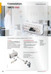
SIDERLoad break switches for power distributionappli_256_a<strong>sider</strong>_089_a_1_cat<strong>sider</strong>_102_a_1_catLoad break switches with visible breakingfrom 125 to 1600 A4‹ FunctionSIDER are manually operated 3 or 4 poleload break switches.They make and break under loadconditions and provide safety isolation forany low voltage electric circuit.2‹ General characteristics• Fully visible breaking.• Visible double breaking.‹ Conformity tostandards•••••IEC 60947-3EN 60947-3VDE 0660-107 (1992)NBN EN 60947-3BS EN 60947-3‹ Approvals andcertifications (1)••••PSA E03.15.605.GRENAULTEB03.15.613UKR (Ukraine)GOST (Russia)(1) Product reference onrequest.<strong>sider</strong>_091_b_1_x_cat13Functional diagram (for further details see the installation instructions suppliedwith every device).1. External front operation2. External side operation3. 2x2 configurable U type ACs, for pre-break and signalling or TEST.4. Terminal shrouds56 General Catalogue 2011-2012 SOCOMEC
Load break switches for power distributionSIDER‹ References<strong>sider</strong>_102_a_2_catFront operationRating (A)No. of polesSwitch bodyDirectoperationSwitch bodyExternaloperation Direct handle External handleShaft forexternal handleAuxiliarycontactsND 125 A3 P 2915 3012 2921 30124 P 2915 4012 2921 4012ND 200 AND 250 AND 315 AND 400 A3 P 2915 3021 2921 30204 P 2915 4021 2921 40203 P 2915 3025 2921 30254 P 2915 4025 2921 40253 P 2915 3031 2921 30314 P 2915 4031 2921 40313 P 2915 3041 2921 30414 P 2915 4041 2921 4041S2 typeBlack IP551421 2111Black(1)Black IP653629 7901 (1) 1423 2111Red IP651424 2111200 mm1400 1020320 mm1400 1032 (1)500 mm1400 10501 st contactNO/NC3999 0021 (2)(3)2 contactsNO/NC3999 0022 (2)(3)1 contact NC3999 0701 (4)(5)1 contact NO3999 0702 (4)(5)ND 500 A3 P 2915 3051 2921 30514 P 2915 4051 2921 4051630 A3 P 2900 3063 2900 30634 P 2900 4063 2900 4063800 A1 250 A3 P 2900 3080 2900 30804 P 2900 4080 2900 40803 P 2900 3120 2900 31204 P 2900 4120 2900 4120Black2799 7012 (1)Red2799 7013S4 typeBlack IP651443 3111 (1)Red/Yellow IP651444 3111200 mm1401 1520320 mm1401 1532 (1)400 mm1401 15401 st inverterNO/NC2799 0001 (2)2 nd contactNO/NC2799 0002 (2)1 600 A3 P 2900 3160 2900 31604 P 2900 4160 2900 4160(1) Standard.(2) Auxiliary signal contact - Type S.(3) For direct operation.(4) For external operation.(5) Auxiliary signal contact - Type U.SOCOMEC General Catalogue 2011-201257
‹ SIDER - References (continued)<strong>sider</strong>_089_a_1_catSide operationRating (A)ND 125 AND 200 AND 250 AND 315 AND 400 AND 500 A630 A800 A1 250 A1 600 ANo. of poles(1) Standard.(2) Auxiliary signal contact - Type S.(3) For direct operation.(4) For external operation.(5) Conversion kit necessary for any direct operation.(6) Auxiliary signal contact - Type U.Switch bodyDirectoperationSwitch bodyExternal rightside operation3 P 2915 3012 2921 30124 P 2915 4012 2921 40123 P 2915 3021 2921 30204 P 2915 4021 2921 40203 P 2915 3025 2921 30254 P 2915 4025 2921 40253 P 2915 3031 2921 30314 P 2915 4031 2921 40313 P 2915 3041 2921 30414 P 2915 4041 2921 40413 P 2915 3051 2921 30514 P 2915 4051 2921 40513 P 2905 3063 2905 30634 P 2905 4063 2905 40633 P 2905 3080 2905 30804 P 2905 4080 2905 40803 P 2905 3120 2905 31204 P 2905 4120 2905 41203 P 2905 3160 2905 31604 P 2905 4160 2905 4160Direct handleExternalhandleS2 typeBlack IP551425 2111 (1)Black Black IP653629 7901 (1) 1427 2111Red/YellowIP651428 2111Black2799 7052 (1) S3 typeConversion kit Black IP652799 7070 (5) 1437 3111 (1)Red Red/Yellow2799 7053 IP65Conversion kit 1438 31112799 7070 (5)Shaft forexternalhandleAuxiliarycontacts1 st contactNO/NC3999 0021 (2)(3)2 contacts200 mm NO/NC1400 1020 (1) 3999 0022 (2)(3)1 contact NC3999 0701 (4)(6)1 contact NO3999 0702 (4)(6)1 st contactNO/NC200 mm 2799 0011 (2)1401 1520 (1) 2 nd contactNO/NC2799 0012 (2)58General Catalogue 2011-2012 SOCOMEC
Load break switches for power distributionSIDER‹ AccessoriesDirect operation handleFor front operationRating (A) Handle colour ReferenceND 125 … ND 500 Black 3629 7901630 … 1 600 Black 2799 7012 (1)630 … 1 600 Red 2799 7013(1) Standard.acces_148_a_1_catacces_153_a_1_catFor side operationRating (A) Handle colour ReferenceND 125 … ND 500 Black 3629 7901630 … 1 600 Black 2799 7052630 … 1 600 Red 2799 7053Direct side escutcheon for operationRating (A) External IP Reference630 … 1 600 IP54 2799 7070External operation handleacces_150_a_3_catS2 type handleacces_166_a_2_catS3 type handleacces_152_a_1_catS4 type handleFor front operationHandleRating (A) colour Handle External IP (1) ReferenceND 125 … ND 500 Black S2 type IP55 1421 2111 (2)ND 125 ND 500 Black S2 type IP65 1423 2111ND 125 … ND 500 Red S2 type IP65 1424 2111630 … 1 600 Black S4 type IP65 1443 3111 (2)630 … 1 600 Red S4 type IP65 1444 3111(1) IP: Degree of protection according to standard IEC 60529.(2) Standard.For right side operationRating (A) HandleHandlecolour External IP (1) ReferenceND 125 … ND 500 S2 type Black IP55 1425 2111ND 125 … ND 500 S2 type Red IP65 1428 2111630 … 1 600 S3 type Black IP65 1437 3111630 … 1 600 S3 type Red IP65 1438 3111(1) IP: Degree of protection according to standard IEC 60529.Shaft guide for external operationUseTo guide the shaft extension into the external handle.This accessory enables handle to engage extension shaft with a misalignment of up to 15 mm.Required for a shaft length over 320 mm.acces_260_a_2_catDescriptionReferenceShaft guide 1429 0000S type handle adapterUseEnables S type handles to be fitted in place ofexisting older style <strong>Socomec</strong> handles. Adaptercan also be utilised as a spacer to increasethe distance between the panel door and thehandle lever.DimensionsAdds 12 mm to the depth.acces_187_a_1_catTo be orderedHandle colour in multiples of External IP (1) ReferenceBlack 10 IP65 1493 0000(1) IP: Degree of protection according to standard IEC 60529.SOCOMEC General Catalogue 2011-201259
‹ SIDER - Accessories (continued)Alternative S type handle cover colorsUseFor single lever handles type S1, S2, S3 and double lever handle, type S4.Other colours: consult us.acces_198_a_1_catHandle colourTo be orderedin multiples of Handle ReferenceLight grey 50 Type S1, S2 1401 0001Dark grey 50 Type S1, S2 1401 0011Light grey 50 S4 type 1401 0031Dark grey 50 S4 type 1401 0041Shaft for external handleacces_202_a_1_x_catacces_143_b_1_catacces_144_b_1_catacces_203_a_1_x_catXYUseStandard lengths:Other lengths: consult us.- 80 mm,- 200 mm,- 320 mm,- 400 mm,- 500 mm.For front operationRating (A)DimensionX (mm)Shaft length(mm) Type ReferenceND 125 … ND 500 95 … 230 200 mm 10 x 10 1400 1020ND 125 … ND 500 95 … 350 320 mm 10 x 10 1400 1032ND 125 … ND 500 95 … 530 500 mm 10 x 10 1400 1050630 … 1 600 295 … 555 200 mm 15 x 12 1401 1520630 … 1 600 295 … 675 320 mm 15 x 12 1401 1532630 … 1 600 295 … 755 400 mm 15 x 12 1401 1540For side operationRating (A)DimensionY (mm)Shaft length(mm) Type ReferenceND 125 … ND 500 20 … 110 80 mm 10 x 10 includedND 125 … ND 500 20 … 230 200 mm 10 x 10 1400 1020630 … 1 600 98 … 258 200 mm 15 x 12 1401 1520Auxiliary contacts for pre-break and signalling - Front operationacces_047_a_2_catacces_056_a_1_catUsePre-break and signalling of positions 0 and I:- 1 to 2 NO/NC auxiliary contacts,- 1 to 4 NO or NC auxiliary contacts.- 1 to 4 NO+NC auxiliary contacts.Connection to the control circuitBy 6.35 mm fast-on terminal.CharacteristicsNO/NC AC: IP2.Electrical characteristics30 000 operations.NO/NC contactRating (A) Position AC ReferenceND 125 … ND 500 1 st 3999 0021 (1)ND 125 … ND 500 2 3999 0022 (1)630 … 1 600 1 st 2799 0001630 … 1 600 2 nd 2799 0002(1) For direct operation.NC contactRating (A) Position AC ReferenceND 125 … ND 500 1 to 4 3999 0701 (1)(1) For direct operation.NO contactRating (A) Position AC ReferenceND 125 … ND 500 1 to 4 3999 0702 (1)(1) For direct operation.NO+NC contactRating (A) Position AC Reference630 … 1 600 1 2799 0005Low level NO/NC auxiliary contactsRating (A) Position AC Reference630 … 1 600 1 2699 0101CharacteristicsOperating current Ie (A)Current 250 VAC 400 VAC 24 VDC 48 VDCRating (A)Contact type nominal (A) AC-13 AC-13 DC-13 DC-13ND 125 … ND 500 inverter NO/NC 16 3 12 2ND 125 … ND 500 NC 10 6 4 5 3ND 125 … ND 500 NO 10 6 4 5 3630 … 1 600 inverter NO/NC 16 12 8 14 6630 … 1 600 NO + NC 15 10 6 15 1260General Catalogue 2011-2012 SOCOMEC
Load break switches for power distributionSIDERAuxiliary contacts for pre-break and signalling - Right side operationNO/NC contactRating (A) Position AC ReferenceND 125 … ND 500 1 st 3999 0021ND 125 … ND 500 2 3999 0022630 … 1 600 1 st 2799 0011630 … 1 600 2 nd 2799 0012acces_047_a_2_catacces_056_a_1_catNC contactRating (A) Position AC ReferenceND 125 … ND 500 1 to 4 3999 0701NO contactRating (A) Position AC ReferenceND 125 … ND 500 1 to 4 3999 0702UsePre-break and signalling of positions 0 and I:- 1 to 2 NO/NC auxiliary contacts,- 1 to 4 NO or NC auxiliary contacts.Connection to the control circuitBy 6.35 mm fast-on terminal.CharacteristicsNO/NC AC: IP2.Electrical characteristics30 000 operations.Low level NO/NC auxiliary contactsRating (A) Position AC Reference630 … 1 600 1 2799 0111CharacteristicsOperating current Ie (A)Current 250 VAC 400 VAC 24 VDC 48 VDCRating (A)Contact typenominal(A) AC-13 AC-13 DC-13 DC-13ND 125 … ND 500 inverter NO/NC 16 3 12 2ND 125 … ND 500 NC 10 6 4 5 3ND 125 … ND 500 NO 10 6 4 5 3630 … 1 600 inverter NO/NC 16 12 8 14 6S type auxiliary contacts for signalisation - Front and right side operationUsePosition 0 and I signalling 1 to 4 NO+NCauxiliary contacts.Connection to the control circuitBy terminals with max. section 10 mm 2 .Electrical principleThe NO+NC S-type auxiliary contacts canbe configured as 2 NO or 2 NC.Electrical characteristics30 000 operations.acces_051_a_2_catNO+NC contactRating (A) Position AC ReferenceND 125 … ND 500 1 3999 0041ND 125 … ND 500 2 3999 0042ND 125 … ND 500 3 3999 0043ND 125 … ND 500 4 3999 0044CharacteristicsOperating current Ie (A)Current 250 VAC 400 VACRating (A)Contact type nominal (A) AC-13 AC-13ND 125 … ND 500 NO + NC 20 10 8Terminal shroudsUseTop or bottom protection against directcontact with terminals or connectionparts.AdvantagePerforations allowing remotethermographic inspection withoutremoval.acces_093_a_1_catRating (A) No. of poles Position ReferenceND 125 … ND 200 3 P top or bottom 3998 3016 (1)ND 125 … ND 200 4 P top or bottom 3998 4016 (2)ND 250 … ND 500 3 P top or bottom 3998 3025 (1)ND 250 … ND 500 4 P top or bottom 3998 4025 (2)(1) Reference composed of 3 pieces.(2) Reference composed of 4 pieces.SOCOMEC General Catalogue 2011-201261
‹ SIDER - Accessories (continued)Terminal screensUseTop or bottom protection against direct contact with terminals or connection parts.acces_058_a_1_catRating (A) No. of poles Position Reference630 … 800 3 P top / bottom 2998 3080630 … 800 4 P top / bottom 2998 40801 250 … 1 600 3 P top / bottom 2998 31201 250 … 1 600 4 P top / bottom 2998 4120Cage terminalsUseConnection of bare copper cables onto the terminals (without lugs).acces_053_a_1_catX1ConnectionsRating (A)Sectionflexible cable (mm 2 )Section rigidcable (mm 2 )Widthflexible bar (mm)ND 125 16 … 95 16 … 95 13 22ND 200 … ND 250 16 … 185 16 … 185 18 27ND 315 … ND 400 50 … 240 50 … 300 20 34ND 500 … 630 70 … 300 70 … 300 24 34Strippedover (mm)DimensionsRating (A) A A1 C R ØX X1 ZND 125 47.5 22.5 25 20 8.5 M12 10ND 200 … ND 250 62 31.5 31.5 25 10.5 M16 14ND 315 … ND 400 71.5 32 38 32 10.5 M20 15ND 500 … 630 76.5 37 38 40 12.5 M20 15acces_091_a_1_x_catøXZA1acces_092_a_1_x_catCARRating (A) No. of poles ReferenceND 125 3 P 5400 3016ND 125 4 P 5400 4016ND 200 … ND 250 3 P 5400 3025ND 200 … ND 250 4 P 5400 4025ND 315 … ND 400 3 P 5400 3040ND 315 … ND 400 4 P 5400 4040ND 500 … 630 3 P 5400 3063ND 500 … 630 4 P 5400 4063Inter phase barrierUseSafety isolation between the terminals, essential for use at 690 VAC or in a polluted ordusty atmosphere.acces_036_a_1_catRating (A) No. of poles Reference630 … 1 600 3 P 2998 0003630 … 1 600 4 P 2998 000462General Catalogue 2011-2012 SOCOMEC
Load break switches for power distributionSIDERHandle key interlocking accessoriesUseLocking in position 0 of front or sideoperation handle:- using RONIS EL11AP lock in directfront or right-side operation (Fig. 1),- using RONIS EL11AP lock in directfront operation (Fig. 2),- using RONIS EL11AP or CASTELLtype K-type lock in external frontoperation (Fig. 3),- using RONIS EL11AP lock in externalright-side operation,- using CASTELL FS-type in externalfront operation (Fig. 4).acces_042_a_1_x_catFig. 1acces_084_a_1_x_catFig.2Locking using RONIS EL11AP lock (not supplied)Rating (A) Operation Figure ReferenceND 125 … ND 500 Front direct 1 3629 7913 (1)630 … 1 600 Front direct 2 2799 7007 (2)ND 125 … 1 600 External front 3 1499 7701ND 125 … ND 500 Direct right side 1 3629 7913 (1)ND 125 … 1 600 External right side 3 1499 7701(1) Handle included.(2) Factory mounting only.acces_158_a_1_x_catFig. 3acces_157_a_1_x_catFig.4Locking using type K CASTELL lock (not supplied)Rating (A) Operation Figure ReferenceND 125 … ND 500 external front 3 1499 7702Locking using type FS CASTELL lock (not supplied)Rating (A) Operation Figure ReferenceND 125 ND 500 external front 4 1499 7703Other specific accessories• Mechanical coupling device for making switches with "n" poles of the same ordifferent ratings.• Mechanical interlocking device.• Mechanical plates and escutcheon for standard systems.bd_03_04_01SOCOMEC General Catalogue 2011-201263
‹ SIDER - Characteristics according to IEC 60947-3ND 125 to ND 500 AThermal current Ith (40°C) ND 125 A ND 200 A ND 250 A ND 315 A ND 400 A ND 500 ARated insulation voltage Ui (V) 800 800 800 800 800 800Rated impulse withstand voltage Uimp (kV) 8 8 8 8 8 8Rated operational currents Ie (A)Rated voltage Load duty category A/B (1) A/B (1) A/B (1) A/B (1) A/B (1) A/B (1)400 VAC AC-21 A / AC-21 B 125/125 200/200 250/250 315/315 400/400 500/500400 VAC AC-22 A / AC-22 B 125/125 200/200 250/250 315/315 400/400 500/500400 VAC AC-23 A / AC-23 B 125/125 200/200 250/250 315/315 400/400 500/500500 VAC AC-20 A / AC-20 B 125/125 200/200 250/250 315/315 400/400 500/500500 VAC AC-21 A / AC-21 B 125/125 160/160 250/250 250/250 315/315 315/315500 VAC AC-22 A / AC-22 B 125/125 160/160 250/250 250/250 315/315 315/315500 VAC AC-23 A / AC-23 B 125/125 160/160 250/250 250/250 315/315 315/315690 VAC (2) AC-20 A / AC-20 B 125/125 200/200 250/250 315/315 400/400 500/500690 VAC (2) AC-21 A / AC-21 B 125/125 160/160 250/250 315/315 400/400 500/500690 VAC (2) AC-22 A / AC-22 B 125/125 160/160 250/250 315/315 400/400 500/500690 VAC (2) AC-23 A / AC-23 B 125/125 160/160 250/250 250/250 315/315 315/315220 VDC DC-20 A / DC-20 B 125/125 200/200 250/250 315/315220 VDC DC-21 A / DC-21 B 125/125 160/160 250/250 250/250220 VDC DC-22 A / DC-22 B 125/125 160/160 250/250 250/250220 VDC DC-23 A / DC-23 B 125/125 125/125 200/200 200/200440 VDC DC-20 A / DC-20 B 125/125 200/200 250/250 315/315440 VDC DC-21 A / DC-21 B 125/125 (3) 160/160 (3) 250/250 (3) 250/250 (3)440 VDC DC-22 A / DC-22 B 125/125 (3) 160/160 (3) 250/250 (3) 250/250 (3)440 VDC DC-23 A / DC-23 B 125/125 (3) 125/125 (3) 200/200 (3) 200/200 (3)500 VDC DC-20 A / DC-20 B 125/125 200/200 250/250 315/315 400/400 500/500500 VDC DC-21 A / DC-21 B 125/125 (3) 160/160 (3) 250/250 (3) 250/250 (3) 315/315 (3) 315/315 (3)500 VDC DC-22 A / DC-22 B 125/125 (3) 160/160 (3) 250/250 (3) 250/250 (3) 315/315 (3) 315/315 (3)500 VDC DC-23 A / DC-23 B 125/125 (3) 125/125 (3) 200/200 (3) 200/200 (3) 200/315 (3) 200/315 (3)Operational power in AC-23 (kW)At 400 VAC without pre-break in AC-23 (kW) (1)(4) 63/63 110/110 140/140 160/160 220/220 295/295At 500 VAC without pre-break in AC-23 (kW) (1)(4) 85/85 110/110 160/160 160/160 220/220 220/220At 690 VAC without pre-break in AC-23 (kW) (1)(4) 110/110 150/150 220/220 220/220 295/295 295/295Reactive power (kvar)At 400 VAC (kvar) (4) 55 90 115 145 185 230Fuse protected short-circuit withstand (kA rms prospective)Prospective short-circuit (kA rms) (5) 100 35 100 60 50 30Associated fuse rating (A) (5) 125 200 250 315 400 500Short-circuit capacityRated short-time withstand current 0.3 s. ICW (kA eff.) 15 15 17 17 17 17Rated peak withstand current (kA peak) (5) 20 20 32.5 32.5 40 40ConnectionMin. connection wire rangeMinimum Cu busbar section (mm 2 )Maximum Cu cable section (mm 2 ) 120 120 240 240 2 x 150 2 x 150Maximum Cu busbar width (mm) 20 20 32 32 45 45Tightening torque min (Nm) 9 9 20 20 20 20Mechanical characteristicsDurability (number of operating cycles) (6) 10 000 10 000 10 000 10 000 10 000 10 000Operating effort (Nm) 10 10 12 12 15 15Weight of a 3 pole device (kg) 1.8 1.8 3.2 3.2 4.8 4.8Weight of a 4 pole device (kg) 2.3 2.3 4.5 4.5 6.1 6.1(1) Category with index A = frequent operation - Category with index B = infrequent operation.(2) With terminal shrouds or phase barrier.(3) 4-pole device with 2 pole in series by polarity.(4) The power value is given for information only, the current values vary from one manufacturer to another.(5) For a rated operational voltage Ue = 400 VAC.(6) Increased endurances: please consult us.64General Catalogue 2011-2012 SOCOMEC
Load break switches for power distributionSIDER630 to 1600 AThermal current Ith (40°C) 630 A 800 A 1 250 A 1 600 ARated insulation voltage Ui (V) 1 000 1 000 1 000 1 000Rated impulse withstand voltage Uimp (kV) 12 12 12 12Rated operational currents Ie (A)Rated voltage Load duty category A/B (1) A/B (1) A/B (1) A/B (1)400 VAC AC-21 A / AC-21 B 630/630 800/800 1 250/1 250 1 600/1 600400 VAC AC-22 A / AC-22 B 630/630 800/800 1 250/1 250 1 250/1 250400 VAC AC-23 A / AC-23 B 630/630 630/800 1 000/1 000 1 000/1 000500 VAC AC-20 A / AC-20 B 630/630 800/800 1 250/1 250 1 600/1 600500 VAC AC-21 A / AC-21 B 630/630 800/800 1 250/1 250 1 600/1 600500 VAC AC-22 A / AC-22 B 630/630 800/800 1 000/1 000 1 000/1 000500 VAC AC-23 A / AC-23 B 500/500 500/500 800/800 800/800690 VAC (2) AC-20 A / AC-20 B 630/630 800/800 1 250/1 250 1 600/1 600690 VAC (2) AC-21 A / AC-21 B 630/630 800/800 1 000/1 000 1 250/1 250690 VAC (2) AC-22 A / AC-22 B 315/315 315/315 400/400 400/400690 VAC (2) AC-23 A / AC-23 B 100/100 125/125 200/200 200/200220 VDC DC-20 A / DC-20 B 630/630 800/800 1 250/1 250 1 600/1 600220 VDC DC-21 A / DC-21 B 630/630 800/800 1 000/1 000 1 250/1 250220 VDC DC-22 A / DC-22 B 630/630 800/800 800/800 800/800220 VDC DC-23 A / DC-23 B 630/630 800/800 800/800 800/800440 VDC DC-20 A / DC-20 B 630/630 800/800 1 250/1 250 1 600/1 600440 VDC DC-21 A / DC-21 B 500/500 630/630 1 000/1 000440 VDC DC-22 A / DC-22 B 630/630 (3) 800/800 (3) 800/800 (3) 800/800 (3)440 VDC DC-23 A / DC-23 B 630/630 (3) 800/800 (3) 800/800 (3) 800/800 (3)500 VDC DC-20 A / DC-20 B 630/630 800/800 1 250/1 250 1 600/1 600500 VDC DC-21 A / DC-21 B 500/500 630/630 800/800 (3) 1 000/1 000500 VDC DC-22 A / DC-22 B 630/630 (3) 800/800 (3) 800/800 (3) 800/800 (3)500 VDC DC-23 A / DC-23 B 630/630 (3) 800/800 (3) 800/800 (3) 800/800 (3)Operational power in AC-23 (kW)At 400 VAC without pre-break in AC-23 (kW) (1)(4) 355/355 355/355 560/560 560/560At 500 VAC without pre-break in AC-23 (kW) (1)(4) 355/355 355/355 560/560 560/560At 690 VAC without pre-break in AC-23 (kW) (1)(4) 90/90 110/110 185/185 185/185Reactive power (kvar)At 400 VAC (kvar) (4) 290 365 575Fuse protected short-circuit withstand (kA rms prospective)Prospective short-circuit (kA rms) (5) 100 70 100 120Associated fuse rating (A) (5) 630 800 1 250 2 x 800Short-circuit capacityRated short-time withstand current 0.3 s. ICW (kA eff.) 50 50 100 100Rated peak withstand current (kA peak) (5) 55 55 100 110ConnectionMin. connection wire range 2 x 150 2 x 185Minimum Cu busbar section (mm 2 ) 2 x 30 x 5 2 x 40 x 5 2 x 60 x 5 2 x 80 x 5Maximum Cu cable section (mm 2 ) 2 x 300 2 x 300 4 x 185 6 x 240Maximum Cu busbar width (mm) 63 63 100 100Tightening torque min (Nm) 20 20 40Mechanical characteristicsDurability (number of operating cycles) (6) 5 000 4 000 4 000 3 000Operating effort (Nm) 45 45 45 60Weight of a 3 pole device (kg) 8 8.5 11 16.5Weight of a 4 pole device (kg) 9.5 10 14 20.5(1) Category with index A = frequent operation - Category with index B = infrequent operation.(2) With terminal shrouds or phase barrier.(3) 4-pole device with 2 pole in series by polarity.(4) The power value is given for information only, the current values vary from one manufacturer to another.(5) For a rated operational voltage Ue = 400 VAC.(6) Increased endurances: please consult us.SOCOMEC General Catalogue 2011-201265
‹ SIDER - DimensionsFront operationSIDER ND 125 to ND 500 ADirect operationL4TTIR270°<strong>sider</strong>_059_b_1_x_catAABANAC01CHYZWTA1. Terminal shrouds2. 1 or 2 NO/NC ACs for pre-break and signalling.Rating(A)Overall dimensions Terminal shrouds Switch body Switch mounting ConnectionA 3p. A 4p. C AC H L N R T W Y Z AA BAND 125 160 196 178 268 82 36 130 5 36 8 3 20 162 141ND 200 160 196 178 268 82 36 130 5 36 8 3 20 162 141ND 250 232 322 173 350 77 31 162 6 60 10 3 20 195 165ND 315 232 322 173 350 77 31 162 6 60 10 3 20 195 165ND 400 280 346 173 360 77 31 172 6 66 10 3 20 214 175ND 500 280 346 173 360 77 31 172 6 66 10 3 20 214 175External front operation95 min.H460fix 60J25R1Ø 78125ACAABAN<strong>sider</strong>_103_c_1_x_cat77.54523 2077.5TTW1. 1 or 2 NO/NC ACs for pre-break and signalling.2. Terminal shroudsFTerminal shrouds Switch body Switch mounting ConnectionRating (A)AC F 3p. F 4p. H J N R T W AA BAND 125 268 148 184 137 54 130 5 36 8 162 141ND 200 268 148 184 137 54 130 5 36 8 162 141ND 250 350 234 294 132 85 162 6 60 10 195 165ND 315 350 234 294 132 85 162 6 60 10 195 165ND 400 360 252 318 132 91 172 6 66 10 214 175ND 500 360 252 318 132 91 172 6 66 10 214 17566General Catalogue 2011-2012 SOCOMEC
Load break switches for power distributionSIDERSIDER 630 to 1600 ADirect front operationExternal front operation12.5MUAFW90.51160ZY295 min.60460AA<strong>sider</strong>_061_e_1_x_catCA BA CA220X11. Terminal screensVTTT11X2 30I8090°0330240 14350Rating(A)Overall dimensions Switch body Switch mounting ConnectionA 3p. A 4p. F 3p. F 4p. M 3p. M 4p. T U V W X1 X2 Y Z AA BA AC630 463 543 358 438 255 335 80 40 50 13 42.5 52.5 6 106 300 260 20800 463 543 358 438 255 335 80 50 60 47.5 47.5 6 106 3201 250 555 675 450 560 347 457 120 63 65 46.5 60.5 7 107 3301 600 555 675 450 560 347 457 120 80 80 46.5 60.5 15 111 360Side operationSIDER ND 125 to ND 500 AExternal side operationHL460fix 60J2577.5R13ACAABA<strong>sider</strong>_090_d_1_x_catN277.5W451253 20TTF1. 1 or 2 NO/NC ACs for pre-break and signalling.2. Terminal shrouds3. Max. length with shaft extension: 230 mmTerminal shrouds Overall dimensions Switch body Switch mounting ConnectionRating (A) AC F 3p. F 4p. H J L N R T W AA BAND 125 268 148 184 137 54 36 130 5 36 8 162 141ND 200 268 148 184 137 54 36 130 5 36 8 162 141ND 250 350 234 294 132 85 31 162 6 60 10 195 165ND 315 350 234 294 132 85 31 162 6 60 10 195 165ND 400 360 252 318 132 91 31 172 6 66 10 214 175ND 500 360 252 318 132 91 31 172 6 66 10 214 175SOCOMEC General Catalogue 2011-201267
‹ SIDER - Dimensions (continued)Side operation (continued)SIDER 630 to 1600 ADirect side operationExternal side operation201ZY=UFMW=721 224030460AA11CA90°28CA BA220VI<strong>sider</strong>_065_c_1_x_cat01. Terminals protection screen2. Max length with shaft extension: 111 mmX1TTT X2A 14Overalldimensions Switch body Switch mounting ConnectionRating (A)A 3p. A 4p. F 3p. F 4p. M 3p. M 4p. T U V W X1 X2 Y Z AA BA AC630 387 467 280 360 255 335 80 40 50 13 42.5 52.5 6 147 300 260 20800 387 467 280 360 255 335 80 50 60 47.5 47.5 6 147 3201 250 479 599 372 492 347 467 120 63 65 46.5 60.5 7 148 3301 600 479 599 372 492 347 467 120 80 80 46.5 60.5 15 152 36061210‹ Dimensions for external handlesSIDER ND 125 to ND 500 AFront operationHandle typeDirection of operationDoor drillingS2 type040With lockRONIS EL11APWith lockCASTELL KØ784512590°IØ 374 Ø 728Ø 264 Ø 5.5Ø 374 Ø 745°14143.526 2473.528Ø 372 Ø 6.5Ø 374 Ø 745°1414792228.520 2020 20Handle typeSide operationDirection of operationDoor drillingS2 typeØ 37<strong>sider</strong>_106_a_1_gb_catØ78S3 typeØ7845125Right side operationI090°With lockRONIS EL11AP4 Ø 5.5Ø 2628284 Ø 740With lockCASTELL K2 Ø 6.5Ø 3728.52104 Ø 745°20 203.5Ø 3726 2473.5Ø 374 Ø 745°20 2079226128 2868General Catalogue 2011-2012 SOCOMEC
Load break switches for power distributionSIDER‹ Dimensions for external handles (continued)SIDER 630 to 1600 AHandle typeFront operationDirection of operationDoor drillingS4 typeØ 37Ø7804035090°284 Ø 7IWith lock RONIS EL11APWith lock CASTELL K<strong>sider</strong>_107_a_1_gb_cat60Ø 264 Ø 5.5Ø 374 Ø 745°20 203.52826 2473.5Ø 372 Ø 6.5Ø 374 Ø 745°20 2028.522792828‹ Connection terminalsSIDER 800 ASIDER 1 250 ASIDER 1 600 Aø19x11ø1516 x 11ø 13303340<strong>sider</strong>_073_a_1_x_cat30335010<strong>sider</strong>_074_a_1_x_cat19 25 196317 25<strong>sider</strong>_075_a_1_x_cat20 40 208020SOCOMEC General Catalogue 2011-201269