- Page 3 and 4:
Contact InformationDynon Avionics,
- Page 5 and 6:
Revision Revision Date DescriptionS
- Page 7:
Revision Revision Date DescriptionA
- Page 12 and 13:
Table of ContentsEthernet Connectio
- Page 14 and 15:
Table of ContentsVP-X SkyView Displ
- Page 16 and 17:
IntroductionAbout this GuideIn the
- Page 18 and 19:
System PlanningTable 4 contains phy
- Page 20 and 21:
System PlanningSV-ADAHRS-200 and SV
- Page 22 and 23:
System PlanningThere are no module-
- Page 24 and 25:
System PlanningServos (SV32, SV42,
- Page 26 and 27:
System Planningon any one of them.
- Page 28 and 29:
System PlanningFigure 5-SkyView Sys
- Page 30 and 31:
System PlanningHSI RequirementsThe
- Page 32 and 33:
Basic SkyView Display OperationDisp
- Page 34 and 35:
Basic SkyView Display OperationA bu
- Page 36: Basic SkyView Display OperationBasi
- Page 41 and 42: Basic SkyView Display OperationGPS
- Page 43: Basic SkyView Display OperationServ
- Page 46 and 47: SV-D700 / SV-D1000 Installation and
- Page 48 and 49: SV-D700 / SV-D1000 Installation and
- Page 50 and 51: SV-D700 / SV-D1000 Installation and
- Page 52 and 53: SV-D700 / SV-D1000 Installation and
- Page 54 and 55: SV-D700 / SV-D1000 Installation and
- Page 56 and 57: SV-D700 / SV-D1000 Installation and
- Page 58 and 59: SV-D700 / SV-D1000 Installation and
- Page 60 and 61: SV-D700 / SV-D1000 Installation and
- Page 62 and 63: SV-D700 / SV-D1000 Installation and
- Page 64 and 65: SV-D700 / SV-D1000 Installation and
- Page 66 and 67: SV-ADAHRS-20X Installation and Conf
- Page 68 and 69: SV-ADAHRS-20X Installation and Conf
- Page 71 and 72: SV-ADAHRS-20X Installation and Conf
- Page 73: SV-ADAHRS-20X Installation and Conf
- Page 76 and 77: SV-ADAHRS-20X Installation and Conf
- Page 78 and 79: SV-ADAHRS-20X Installation and Conf
- Page 81 and 82: 7. SV-EMS-220 Installation and Conf
- Page 83 and 84: SkyView Network ConnectionSV-EMS-22
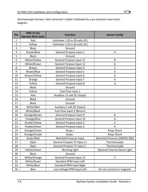
- Page 85: SV-EMS-220 Installation and Configu
- Page 89 and 90: SV-EMS-220 Installation and Configu
- Page 91 and 92: SV-EMS-220 Installation and Configu
- Page 93 and 94: SV-EMS-220 Installation and Configu
- Page 95 and 96: SV-EMS-220 Installation and Configu
- Page 97 and 98: SV-EMS-220 Installation and Configu
- Page 99 and 100: SV-EMS-220 Installation and Configu
- Page 101 and 102: SV-EMS-220 Installation and Configu
- Page 103 and 104: SV-EMS-220 Installation and Configu
- Page 105 and 106: Tools and Equipment RequiredSV-EMS-
- Page 107 and 108: SV-EMS-220 Installation and Configu
- Page 109 and 110: Note that you may need access to th
- Page 111 and 112: Fuel Pressure SensorSV-EMS-220 Inst
- Page 113 and 114: SV-EMS-220 Installation and Configu
- Page 115 and 116: SV-EMS-220 Installation and Configu
- Page 117 and 118: SV-EMS-220 Installation and Configu
- Page 119 and 120: SV-EMS-220 Installation and Configu
- Page 121 and 122: SV-EMS-220 Installation and Configu
- Page 123 and 124: EMS Sensor Input MappingSV-EMS-220
- Page 125 and 126: SV-EMS-220 Installation and Configu
- Page 127 and 128: SV-EMS-220 Installation and Configu
- Page 129 and 130: Example Contact Sensor SetupAssume
- Page 131 and 132: SV-EMS-220 Installation and Configu
- Page 133 and 134: SV-EMS-220 Installation and Configu
- Page 135 and 136: 8. SV-GPS-250 Installation and Conf
- Page 137 and 138:
SV-GPS-250 Installation and Configu
- Page 139 and 140:
9. SV-BAT-320 InstallationThis chap
- Page 141:
Battery Status CheckSV-BAT-320 Inst
- Page 144 and 145:
Autopilot Servo Installation, Confi
- Page 146 and 147:
Autopilot Servo Installation, Confi
- Page 148 and 149:
Autopilot Servo Installation, Confi
- Page 150 and 151:
Autopilot Servo Installation, Confi
- Page 152 and 153:
Autopilot Servo Installation, Confi
- Page 154 and 155:
Autopilot Servo Installation, Confi
- Page 156 and 157:
Autopilot Servo Installation, Confi
- Page 158 and 159:
Autopilot Servo Installation, Confi
- Page 160 and 161:
Autopilot Servo Installation, Confi
- Page 162 and 163:
Autopilot Servo Installation, Confi
- Page 164 and 165:
Autopilot Servo Installation, Confi
- Page 166 and 167:
Autopilot Servo Installation, Confi
- Page 168 and 169:
Autopilot Servo Installation, Confi
- Page 170 and 171:
Autopilot Servo Installation, Confi
- Page 173 and 174:
11. SV-XPNDR-26X Installation, Conf
- Page 175 and 176:
SV-XPNDR-26X Installation, Configur
- Page 177 and 178:
SV-XPNDR-26X Installation, Configur
- Page 179 and 180:
Power/Ground InputSV-XPNDR-26X Inst
- Page 181 and 182:
Serial GPS Position Input (Future U
- Page 183 and 184:
SV-XPNDR-26X Installation, Configur
- Page 185 and 186:
SV-XPNDR-26X Installation, Configur
- Page 187 and 188:
Altitude Encoder CalibrationSV-XPND
- Page 189 and 190:
12. SV-ARINC-429 Installation and C
- Page 191 and 192:
SV-ARINC-429 Installation and Confi
- Page 193 and 194:
ARINC Device ConnectionsSV-ARINC-42
- Page 195 and 196:
SV-ARINC-429 Installation and Confi
- Page 197:
SV-ARINC-429 Installation and Confi
- Page 200 and 201:
SV-ARINC-429 Installation and Confi
- Page 202 and 203:
SV-ARINC-429 Installation and Confi
- Page 204 and 205:
Accessory Installation and Configur
- Page 206 and 207:
Accessory Installation and Configur
- Page 208 and 209:
Accessory Installation and Configur
- Page 210 and 211:
Accessory Installation and Configur
- Page 212 and 213:
Accessory Installation and Configur
- Page 214 and 215:
Accessory Installation and Configur
- Page 217 and 218:
15. Appendix A: Maintenance and Tro
- Page 219 and 220:
Appendix A: Maintenance and Trouble
- Page 221 and 222:
Display Input VoltageThe display's
- Page 223 and 224:
Appendix A: Maintenance and Trouble
- Page 225:
Appendix A: Maintenance and Trouble
- Page 228 and 229:
Appendix B: SpecificationsSkyView C
- Page 230 and 231:
Appendix B: SpecificationsSV-XPNDR-
- Page 232 and 233:
Appendix C: Wiring and Electrical C
- Page 234 and 235:
Appendix C: Wiring and Electrical C
- Page 236 and 237:
Appendix C: Wiring and Electrical C
- Page 238 and 239:
Appendix C: Wiring and Electrical C
- Page 240 and 241:
Appendix C: Wiring and Electrical C
- Page 242 and 243:
Appendix C: Wiring and Electrical C
- Page 244 and 245:
Appendix C: Wiring and Electrical C
- Page 246 and 247:
Appendix C: Wiring and Electrical C
- Page 249 and 250:
18. Appendix D: SV-EMS-220 Sensor I
- Page 251 and 252:
19. Appendix E: Serial Data OutputA
- Page 253 and 254:
` Appendix E: Serial Data OutputPar
- Page 255 and 256:
` Appendix E: Serial Data OutputDYN
- Page 257 and 258:
` Appendix E: Serial Data OutputPar
- Page 259 and 260:
` Appendix E: Serial Data OutputPar
- Page 261 and 262:
` Appendix E: Serial Data OutputPar
- Page 263 and 264:
` Appendix E: Serial Data Output!11