Audiomaster 1200 Powermixer - Shure
Audiomaster 1200 Powermixer - Shure
Audiomaster 1200 Powermixer - Shure

Create successful ePaper yourself
Turn your PDF publications into a flip-book with our unique Google optimized e-Paper software.
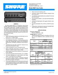
Price $7.50Model <strong>1200</strong> <strong>Powermixer</strong>SERVICE MANUALISSUE NO. 1Manufactured bySHURE BROTHERS INC.222 Hartrey AvenueEvanston, Illinois 60202-3696Copyright 1988, <strong>Shure</strong> Brothers Inc.AL954 (HE) 27A8187Printed in U.S.A.
SPECIFICATIONSTypeMono <strong>Powermixer</strong>Frequency ResponseFlat +1, -3 dB, 40 Hz to 20 kHz (any input to any output)InputsSix input channels: six unbalanced high- and/or balancedlow-impedance inputs; channels 1 and 2 highimpedanceinputs switchable to Aux level; availableexpansion modules* each contain 2 high- and 2 lowimpedancemicrophone inputs; two modules (4 channels)can be added to each <strong>1200</strong>Power Output (1 kHz, 120 Vac, 1% THD)200 watts minimum with 4 ohm speaker120 watts minimum with 8 ohm speakerDistortionTHD typically less than 0.15% at 1 kHz, 0.35% at 70 Hzand 20 kHz (180 watts to 4 ohms, measured from lowimpedanceinput, Input Attenuation, individual channeland Master Volume controls at typical user settings)IM distortion typically less than 0.4% (116 watts to 4ohms, Input Attenuation, individual channel and MasterVolume controls at typical user settings)Low- and High-Frequency Equalization (Individual channeland Monitor)±10 dB at 100 Hz and 10 kHzInput OVERLOAD IndicatorsIlluminate 3 dB before clipping of input preamplifier orequalizer stagePower Amp LimiterThreshold: 1.5 dB below speaker output clipping levelInput signal range: 15 dB beyond limiting thresholdOutput PEAK/LIMIT IndicatorWith Limiter Out: Lights 2 dB before clipping at speakeroutputsWith Limiter In: Lights 0.5 dB before onset of LimiteractionOutput NORMAL IndicatorLights when speaker output level is greater than 1.4Vrms (0.5 W into 4 ohms)Input Sensitivity (full power output)BAL LO Z: -66 dBV (0.5 mV)HI Z: -44 dBV (6.3 mV)AUX: -26 dBV (50 mV)PA INPUT: 0 dBV (1.0 V)Input Clipping LevelINPUT CLIPPING LEVEL ATTENUATIONBAL LO Z -33 to -3 dBV 0 to -30(22 to 707 mV)HI Z -11 to +18 dBV 0 to -30(281 mV to 8.41 V)AUX +6 to +36 dBV 0 to -302 to 63 VPA INPUT -1 dBV - -(891 mV)Voltage Gain (at 1 kHz)INPUTOUTPUTSPEAKER PGM MIX MONITOR PHONES TAPELO Z 95 dB 65 dB 71 dB 82 dB 51 dBHI Z 73 dB 43 dB 49 dB 60 dB 29 dBAUX 55 dB 25 dB 31 dB 42 dB 11 dBPA 29 dB - - 16 dB -Output Clipping LevelOUTPUTSPEAKERMONITORPROGRAM MIXPHONESTAPEImpedanceINPUTSLO Z MICHI Z MICAUXPAOUTPUTSMONITORPROGRAM MIXTAPEPHONESSPEAKERMINIMUM CLIPPING LEVEL+29 dBV (28 V)+18 dBV (7.9 V)+18 dBV (7.9 V)+16 dBV (6.3 V)+18 dBV (7.9 V)ACTUAL FOR USE WITH1 kΩ 75 to 600 Ω130 kΩ 100 kΩ or less50 kΩ 10 kΩ or less50 kΩ 10 kΩ or less2.4 kΩ 2 kΩ or more2.4 kΩ 2 kΩ or more2.4 kΩ 2 kΩ or more430 Ω 4 Ω or more- 4 Ω or moreHum and NoiseLess than -126 dBV equivalent input hum and noise(20 Hz to 20 kHz, LO Z input to SPEAKER output)NoiseLess than -127 dBV equivalent input noise (300 Hz to20 kHz, LO Z input to SPEAKER output)Signal-to-Noise RatioGreater than 80 dB (below full output) at typical controlsettingsPhantom Power24 Vdc ± 10% open circuit, 1.8 k series resistancePower Requirements120 Vac ± 10%, 50/60 Hz, 420 watts typical with no acreceptacle loadAC Convenience Receptacle120 Vac, 100 watts maximumCertificationsListed by Underwriters Laboratories Inc. and byCanadian Standards Association as certifiedEnvironmental ConditionsOperating Temperature: -7 to 43°C (20 to 110°F)Storage Temperature: -40 to 74°C (-40 to 165°F)Relative Humidity (Operating and Storage): 0 to 95%Overall Dimensions191 mm H x 483 mm W x 343 mm D (7-½ x 19 x 13-½ in.)Weight12.3 kg (27 lb)18.2 kg (40 lb) in A<strong>1200</strong>C Carrying CaseRECOMMENDED LOUDSPEAKERSAUDIOMASTER Model 3200, 100 W, 8 Ω, vented two-wayspeakersOPTIONAL ACCESSORIESCarrying Case. . . . . . . . . . . . . . . . . . . . . . . . . . . . . . . . A<strong>1200</strong>CInput Expansion Module*(2 channels, 2 each HI Z and LO Z inputs). . A<strong>1200</strong>MXSpeaker Cable, 15 m (50 ft) with phone plugs . . . . . . A50SCLine Matching Transformer (LO Z to HI Z) . . . . . . . . . A95UF240-V Conversion Kit* . . . . . . . . . . . . . . . . . . . . . . . . RKC209Phono Preamp . . . . . . . . . . . . . . . . . . . . . . . . . . . . . . . . . M64A*For installation by qualified service personnel only.
MODEL <strong>1200</strong> SERVICE MANUALTABLE OF CONTENTSDescription ..................................... 1For Years of Dependable Service .................... 2Troubleshooting .................................. 2Service Instructions ............................... 3External Parts .................................. 3Diagnosis ..................................... 3External Fuse Replacement ....................... 3Service Access ................................. 3General Service Procedure ....................... 4AC Voltage Measurements ........................ 5DC Voltage Measurements ........................ 5Resistance Measurements ........................ 5Chassis-Mounted Boards and Components .......... 5A1 Reverb Pan ............................... 5SHR-11 (and SHR12) Power AmplifierBoard Assembly ............................. 5SHR-11 Potentiometer Adjust .................. 5VR1101 Output Voltage Offset ................ 6VR1102 Driver Balance ..................... 6VR1103 Idle Current ....................... 6SHR-12 Temperature Sensor Board ............... 6VR1201 Temperature Sensor Threshold .......... 6SHR-14 Main Board ........................... 6VR1401 Power Amplifier Limiter Threshold ........ 7Rear-Panel Boards and Components ............... 7SHR-10 Input-Output Board ..................... 7SHR-03 Aux/Mic Board ........................ 7SHR-02 Hi-Z Input Board ....................... 7SHR-01 Lo-Z Input Board. ...................... 7SHR-13 Speaker Output Board .................. 7B1 Fan ...................................... 7S3 Phantom Power Switch ...................... 8Front-Panel Boards and Components ............... 8SHR-04 Channel Board (6). ..................... 8Front Mounting Panel .......................... 8SHR-05 Master Control Board ................... 8SHR-09 Limiter Board ......................... 8SHR-06 Headphones Output Board andSHR-07 Headphones Control Board ............. 8SHR-08 Indicators Board ....................... 8S2 On/Off Switch ............................. 8A<strong>1200</strong>MX Input Expansion Module ................. 9Checking Active Components ..................... 9Ferrite Beads .................................. 9Service Illustrations ............................. 9Optional Accessories ............................ 9
DESCRIPTIONThe <strong>Shure</strong> Model <strong>1200</strong> AUDIOMASTER ® <strong>Powermixer</strong> is acompact, flexible microphone mixer with six inputs for high- orlow-impedance sources and a 200-watt power amplifier. The<strong>1200</strong> is human-engineered for ease of setup and operation.Connection of microphones, speakers and other equipment(tape recorder, equalizer, effects device, remote amp, etc.) isfast and convenient.The <strong>1200</strong> is rack-mountable or portable. Its 6 inputs areexpandable to 8 or 10 inputs through the use of A<strong>1200</strong>MXExpansion Kits. Inputs accept both high- and low-impedancemicrophones (dynamic, ribbon or condenser), as well as amplifiedinstruments or other high-level sources. Individual channelinput attenuators with overload indicators permit precise gaincontrol to prevent input overload. The <strong>1200</strong> has built-in reverberationwith individual channel and overall level adjustments.Other effects devices or an equalizer can be connected througha post-master control program loop. An integral power amplimiter prevents overload distortion over a wide signal inputrange. Pre-volume monitor send controls and pre-master volumetape output provide maximum versatility in stage or recordingapplications. The control panel has color-coded knobs forease of adjustments, while LED indicators give instant notice ofoperating status.In addition to the A<strong>1200</strong>MX Expansion Module, the followingaccessories are available for the <strong>1200</strong>: A<strong>1200</strong>C Carrying Case,A95UF Line Matching Transformer, RKC209 240 V ConversionKit, and M64A Phono Preamplifier.The <strong>1200</strong> is Listed by Underwriters Laboratories, Inc., andlisted by Canadian Standards Association as certified.1
FOR YEARS OF DEPENDABLE OPERATION...The AUDIOMASTER ® System is exceptionally well designed,with all components of the highest quality, operating well withintheir respective ratings to assure long life. The following list ofDo’s and Don’ts describes minimal operating precautions andmaintenance to provide years of dependable service.DO use a 16 AWG or larger, heavy-duty, 3-conductor extensioncord when additional line cord length is needed.DON’T replace the rear-panel fuse with a different size or type.Use only 5 A, 250 V, Type 3AG.DON’T operate the <strong>Powermixer</strong> with its air vents blocked; don’tplace it on a radiator or heat-producing equipment. Avoid operationin direct, hot sunlight.DO unplug the <strong>Powermixer</strong> before cleaning. Use only milddetergent and a damp (never wet) cloth to clean the outersurfaces; Don’t use strong solvents or cleaning fluids.DON't use unbalanced low-impedance microphones with thePHANTOM 24V switch on; turn off the switch if not required forpowering condenser microphones. If phantom power is in use,connect unbalanced low-impedance microphones through aline matching transformer (<strong>Shure</strong> A95UF) to a HI Z input. Phantompower will not affect balanced low-impedance dynamicmicrophones.DON’T risk fire or shock hazard by operating the Model <strong>1200</strong>in the rain.TROUBLESHOOTlNGShould any difficulty be encountered in operation of your AUDIO-MASTER System, the trouble can often be traced to somesimple source. The following is offered as a basic guide tosolving this kind of problem.SYMPTOM<strong>Powermixer</strong> is “dead” (no output, POWER LED off)PROBABLE CAUSE AND CORRECTION1. Check that ac power source is “live” and Model <strong>1200</strong> isplugged in.2. Check that POWER switch is on.3. Check that rear panel fuse (5 A, 250 V) is good.4. If the <strong>1200</strong> has turned off due to excessive internal temperatures,allow at least an hour for cooling, and reactivate unit.If difficulty persists, refer to General Service Procedure inthis manual.OVERLOAD LED illuminates, eitherA. Flickering with program material, indicating abnormal 1. Check total speaker load (must be no lower than 4 ohms)speaker loadand for possible shorted speaker cable.B. Continuously to indicate power amplifier shutdown 1. Check air vents for blockage.2. Check that internal fan is operating (fan located on rearpanel).3. Turn MASTER volume control down for several minutes toallow proper cooling. If difficulty persists, refer to GeneralService Procedure.No signal at speaker (all other functions appear normal), eitherA. NORMAL LED illuminated, or 1. Check for defective or improperly connected speaker cables.B. NORMAL LED not illuminated 1. Check settings of channel VOLUME and MASTER VOLUMEcontrols.2. Check connections to EXTERNAL DEVICE LOOPFuse blownOne of two inputs on same channel not working properly (both1/4-inch and 3-pin jacks in use)1. Replace with identical fuse (5 A, 250 V, 3AG).2. If second fuse blows, refer to General Service Procedure.1. Make sure similar microphones are used on both inputs,and microphone impedances match the inputs used.2. Make sure a low-impedance microphone is not used withaux level equipment on other input.3. Make sure MIC/AUX switch is in MIC position (Ch. 1 and 2only).4. Make sure microphone switches are on; check microphonecables.2
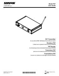
SYMPTOMINPUT OVERLOAD LED flashingNOTE: Occasional flashing is acceptableLoud clicks when certain microphones or cables are usedNo MONITOR output (program output normal)Sound quality poor (weak or thin)PROBABLE CAUSE AND CORRECTION1. Adjust INPUT ATTENUATION counterclockwise to reducechannel input level.2. Reduce input signal level at source.1. Make sure PHANTOM 24V switch is not on (when not needed).2. Make sure unbalanced low-impedance microphone or cableis not used when PHANTOM switch is on.3. Check for defective microphone cables.1. Make sure channel MONITOR and MONITOR MASTERcontrols are turned up.2. Make sure controls on external equipment connected toMonitor output jack are turned up.3. Check for defective cable from MONITOR output jack.1. Check for excessive treble boost or bass cut on equalizationcontrols.2. Check PROGRAM and MONITOR output jacks for signalquality (if acceptable, problem is in power amplifier section).3. Check for defective cables.4. Check impedance match (high- or low-impedance mics)at input.SERVICE INSTRUCTIONSEXTERNAL PARTSThe knobs and feet can be replaced without disassemblingthe <strong>1200</strong>. All knobs are of the pull-off type, and are color-codedby function. The Equalization knobs are dual concentric types;all other knobs are single.DIAGNOSISA simple method of localizing problems without opening the<strong>1200</strong> is as follows. Turn off the Power switch. Do not connect aspeaker or headphone load. Set all controls of the channelunder test only to full clockwise (other channel volume andmonitor controls full counterclockwise), except: Reverb Returnfull counterclockwise, and Eq controls centered. Turn the uniton and apply a 0.5 mV, 1 kHz test signal across pins 2 and 3 ofone of the Bal Lo Z input connectors. Normal voltmeter readingstaken at each output connector are given in Table 1. Similarly, a5 mV signal inserted in a HI Z input, 50 mV in an AUX input, or891 mV in the Power Amp and Monitor Inputs will yield similaroutput voltages. This method is useful for saving time in localizingproblem areas. Internal servicing should be performed onlyby qualified service personnel.TABLE 1. NOMINAL TEST VOLTAGESOUTPUTSINPUT Input Spkr Prgm Mix Mon Phones TapeLO z 0.5 mV 28 V 890 mV 1.78 V 6.31 V 178 mVHI Z 5 mV 22 V 708 mV 1.41 V 5.01 V 141 mVAUX 50 mV 28 V 890 mV 1.78 V 6.31 V 178 mVPA 891 mV 25 V --- --- 5.62 V ---WARNINGVoltages in this equipment are hazardous to life. Referservicing to qualified service personnel.EXTERNAL FUSE REPLACEMENTTo replace line fuse F1 (with no apparent problems in the<strong>Powermixer</strong>), disconnect the line cord from the ac source andremove the rear panel fuseholder cap by pushing it in andturning it counterclockwise (either a screwdriver or fingertipmay be used.) Replace the defective fuse only with a 5A 250VNormal Blow type.CAUTIONIf trouble symptoms (overheating, erratic operation, etc.)were apparent before the fuse blew, or if the replacementfuse blows, a qualified service person should troubleshootthe <strong>Powermixer</strong> carefully to find the source of theproblem. Do not continue to replace fuses; have thetrouble corrected.SERVICE ACCESSDisconnect the <strong>1200</strong> from its power source. To open the unitfor servicing, remove ten screws and lockwashers from the topand five from each side of the cover. The cover can then belifted off exposing the internal parts (see Figure 1).3
PRINTED CIRCUIT BOARD AND PARTS LOCATIONFIGURE 1WARNINGAfter replacing high-voltage parts such as the fan, powercord, rear panel convenience receptacle, or printed wiringassemblies SHR-11, SHR-12, or SHR-14 (or theircomponents), make certain that a dielectric voltagebreakdown test is performed before connecting the unitto a power supply. With the unit disconnected from the acsource, turn the unit on and measure the resistancebetween the ground contact of the power plug and eachof the other two prongs. This resistance should measureinfinite. Then measure the resistance between the plugground and exposed metal parts of the chassis, screws,connectors, fan grille, etc. This resistance should be zeroohms. If any measurements are recorded outside thespecified limits, a shock hazard exists. The unit must berepaired and rechecked before it is returned to operation.IMPORTANT: When removing any printed wiring board, be surethe wires and connectors detached from the board are identifiedfor proper reconnection. This may be done by affixing a pieceof masking tape marked with the reference designation(connectors) or terminal letter or color (wires).NOTE: Any cable ties that were loosened or removed must betightened or replaced after servicing.CAUTIONSimilar wire colors and connectors with the same numberof pins are used in different circuits; make sure properreconnections are made. Push-on connectors must beremoved by pulling straight out. The side of a small screwdriverblade inserted between the free and fixed connectorcan sometimes be helpful in separating the connector.Do not apply side force when removing or reconnectingterminals, or damage may result. Reference to the serviceillustrations will be helpful in case of difficulty.GENERAL SERVICE PROCEDURETo isolate a problem area, a general procedure is as follows. Ifthe <strong>Powermixer</strong> is completely dead, check the ac power source,line cord, and fuses (external and internal). If the unit turns onbut operation is abnormal, check the chassis power supplyoutput (-56 Vdc between test point SHR-11-AB and ground,and +56 Vdc between test point SHR-11-AA and ground; -15Vdc across C1421, +15 Vdc across C1420, and +24 Vdcbetween P1404-A and ground). If the measured dc voltages arecorrect, perform additional AC and DC Voltage Measurementsas described below to isolate the problem.4
AC VOLTAGE MEASUREMENTSNumbers within rectangular symbols on the circuit diagramsdenote ac voltages at that point under the following testconditions:1. Voltages measured with respect to chassis unless otherwiseindicated.2. Line voltage: 120 V, 60 Hz.3. Test signal of 0.5 mV across pins 2 and 3 of connectorJ101.4. AC voltage measurements may vary ±20% from valuesshown.5. Measurements made with ac voltmeter of 1 megohm orgreater input impedance.6. No load on Speaker Outputs.7. All controls (of channel under test only) full clockwiseexcept Equalization controls centered.8. Reverb Return full counterclockwise.9. Limiter switch and Phantom switch in Off position.10. Monitor Master control clockwise.DC VOLTAGE MEASUREMENTSNumbers within elliptical symbols on the circuit diagramsdenote dc voltages at that point under the following testconditions:1. Voltages measured with respect to chassis unless otherwiseindicated.2. Line voltage: 120 V, 60 Hz.3. No input signal applied.4. Dc voltage measurements may vary ±20% from valuesshown.5. Measurements made with dc voltmeter of 11 megohms orgreater input impedance.6. Phantom switch in On position.RESISTANCE MEASUREMENTSWith the ac line cord disconnected from the ac source andthe Power On/Off switch off, the following ohmmeter measurementsmay be made.1. Reverb pan output coil: approximately 360 ohms; inputcoils approximately 40 ohms.2. Transformers may be checked for continuity of each winding.3. To test transistors, ICs and diodes, refer to the section onCHECKING ACTIVE COMPONENTS.CHASSIS-MOUNTED BOARDS AND COMPONENTSThe following printed wiring boards and components arechassis-mounted.SHR-11 POWER BOARDSHR-12 SENSOR BOARDSHR-14 MAIN BOARDA1 REVERB PANT1 POWER TRANSFORMERREVERB PANTo remove the reverb pan assembly, turn the <strong>1200</strong> on its side(power transformer down) and remove the three screws holdingthe reverb shield to the chassis bottom. Turn the <strong>1200</strong> uprightand remove the screw holding the reverb shield to the standoffattached to the parallel vertical interior shield. Disconnect thephono connectors at the bottom of the reverb pan assembly.Remove the four screws holding the reverb pan to the verticalmetal interior shield, and lift the reverb shield and pan assemblyout of the chassis holding the pan to the shield. (If necessary tofree the reverb shield, remove the cable tie(s) holding theorange and white leads to the metal shield.)To replace the reverb pan, connect the white lead connectorto the reverb Input and the orange lead connector to the reverbOutput. Use the previously removed screws to secure the reverbpan to the reverb shield, and to secure the shield to the chassisbottom and the parallel vertical interior shield. Be sure to replaceany cable ties that were removed or loosened.SHR-11 AND SHR-12 POWER AMP BOARD ASSEMBLYThe Power Amplifier Board Assembly consists of SHR-11and SHR-12 mounted on the large aluminum heat sink. Toseparate the heat sink and its associated boards from the <strong>1200</strong>,remove the screws holding the sink to the power transformershield bracket, and those holding the sink to the metal shieldthat divides the fan from the input and output connectors andboards. Disconnect the connectors from P1101, P1102 andP1201, and unsolder the red, green, and white leads from AA,AB and AC, respectively, on SHR-11. (The opposite ends ofleads AA and AB are connected to SHR-14, Main Board; theopposite end of lead AC is connected to SHR-13, SpeakerOutput Board.) The Power Amp Board is now free of the <strong>1200</strong>.To replace parts on SHR-11, it is then necessary to removeSHR-11 from the large heat sink. Do this by removing the fourPhillips screws holding the power transistors at the corners ofthe board, and the two Phillips screws holding the board on thebrass standoffs.NOTES:1. Removal of SHR-11 from the heat sink may damage theinsulators below the power transistors. Therefore, whenservicing SHR-11, be prepared to replace all four 802639FKinsulators. If either predriver transistor Q1103 or Q1104(mounted on the vertical heat sink fastened to SHR-11)is replaced, be prepared to replace insulator 802681FKbeneath it.2. If transistor Q1105, mounted on the solder side of boardSHR-11, is replaced or if the board has been removed fromthe heat sink, make certain that Q1105 physically contactsthe large heat sink after reassembly of the board to the heatsink is completed. Apply a small amount of Wakefield Type120 Thermal Joint Compound to the top surface of thetransistor in order to ensure proper heat transfer.To replace SHR-11 in the <strong>1200</strong>, solder the red, green andwhite leads to AA, AB and AC. Connect the cable assembly withthree leads from P1405, SHR-14, to P1101 ; and connect thecable with a single lead from P1407, SHR-14, to P1102.SHR-11 POTENTIOMETER ADJUSTMENTIf any components are replaced on SHR-11, trimpots VR1101,VR1102 and VR1103 may require readjustment. Measure theSHR-11 voltages described in the following paragraphs. Ifmeasured voltages are not correct, make adjustments as follows.With power off, no input signal applied, and no load on the<strong>1200</strong>’s speaker output, turn VR1103 completely clockwise. Turnpower on and allow unit to warm up or thermally stabilize for tenminutes prior to making the adjustments. See Figure 2 fortrimpot locations.5
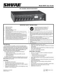
VR1101 OUTPUT VOLTAGE OFFSET ADJUSTMENT1. Connect a dc voltmeter between SHR-11 terminal AC andground (see Figure 2).2. Adjust VR1101 so that V1 equals 0 V ±15 mVVR1102 DRIVER BALANCE ADJUSTMENT1. Connect a dc voltmeter between CP1101 and ground (seeFigure 2).2. Adjust VR1102 so that V2 equals 1.2 V.VR1103 IDLE CURRENT ADJUSTMENT1. After the unit has been turned on for at least five minutes,connect a dc voltmeter between R1126 and R1127 as shown(see Figure 2) and check the idle current. If the value of V3does not equal 6.6 mV ±3.3 mV, use a razor blade to carefullyremove from the top and side of VR1103 the old cement thatprevented its adjustment from changing.2. Adjust VR1103 so that V3 equals 6.6 mV ±3.3 mV.3. Apply a drop of cement (white glue, hot melt glue, caulk, etc.)to VR1103 to eliminate movement due to vibration.VR1201 TEMPERATURE SENSOR THRESHOLD ADJUSTMENTIf U1201 or other SHR-12 parts are replaced, VR1201 willprobably require recalibration as follows.1. Turn off the unit long enough for the heat sink to reachambient temperature. Remove all input signal sources andspeaker loads.2. Measure the heat sink temperature or ambient temperaturearound the heat sink. Consult the graph in Figure 3 todetermine the proper voltage at test point CP1402.3. Attach a dc voltmeter between CP1402 (+) and ground (-).4. Apply power to the unit and quickly adjust potentiometerVR1201 on SHR-12 until the proper voltage is reached.TEMPERATURE SHUTDOWN SENSOR CALIBRATIONFIGURE 3SHR-11 POTENTIOMETER ADJUSTMENTSFIGURE 2SHR-12 TEMPERATURE SENSOR BOARDTo remove SHR-12 from the large heat sink, remove thePower Amplifier Board Assembly from the <strong>1200</strong> as describedabove. Then remove the two Phillips screws that hold SHR-12 tothe small vertical heat sink. When replacing SHR-12, U1201(mounted on the solder side of the board) must physicallycontact the vertical heat sink in order to ensure correct operationof the power amplifier over-temperature protection circuitry.In addition, apply a small amount of Wakefield Type 120 ThermalJoint Compound to the top surface of the IC to allow good heattransfer.SHR-14 MAIN BOARDThe <strong>1200</strong> contains four internal fuses mounted on the MainBoard (SHR-14). If replacement becomes necessary, replaceonly with identical Normal Blow fuses: two 0.75 A 250 V, and two8 A 250 V. Do not continue to replace fuses if a fuse continues toblow; have the trouble corrected.To remove SHR-14 from the chassis, remove the three Phillipsscrews on each of the long sides of the board and the singlescrew next to the two 8 A fuses on the short side of the board.This will allow the board to be lifted free of the chassis. If it isnecessary to completely separate SHR-14 from the <strong>1200</strong>,remove all seven connectors (be sure to label the four 4-pinconnectors and their receptacles to ensure proper reattachment).Unsolder the six transformer and two fan leads from pins AAthrough AH, and the two ground leads connected to Al and AJ.Be sure to label leads also so they can be resoldered to theproper pins. Unsolder from connection pins AA and AB ofSHR-11 the red and green wires attached to the solder side ofSHR-14. (Remove cable ties as necessary.) The SHR-14 boardcan now be completely detached from the <strong>1200</strong>.6
If any of the heat-sink-mounted parts (voltage regulatorsU1408, U1409 and U1410, or silicon rectifiers D1423 and D1424)is replaced, be sure to apply a small amount of Wakefield Type120 Thermal Joint Compound between the component and theheat sink to allow maximum heat transfer.A number of components on SHR-14 are mounted on spacinginsulators to keep them a measured distance from the board,e.g., R1460, D1422. If any of these parts is replaced, be sure toremount them the required distance above the board on spacinginsulators as originally supplied.VR1401 POWER AMPLIFIER LIMITER THRESHOLD ADJUSTMENTThis adjustment is made under the following conditions.1. Terminate the Speaker Output in a 4-ohm resistive load.2. Set the Master control and trimpot VR1401 on SHR-14 fullyclockwise.3. Set the Limiter switch to Out.4. Connect the unit to a 120 Vac, 60 Hz power source andswitch the unit on.5. Drive one low-impedance input channel at 1 kHz with itschannel control fully clockwise. (Turn all the other inputchannel Volume Controls fully counterclockwise.) Increasethe input signal until the signal at the Speaker Output justvisibly clips.6. Reduce the input signal level such that the output voltagedrops 1.5 dB.7. Switch the Limiter In. Slowly turn trimpot VR1401 counterclockwiseuntil the output voltage drops an additional 0.2 dB.REAR-PANEL BOARDS AND COMPONENTSThe following printed circuit boards and components aremounted on the rear panel.SHR-10 INPUT-OUTPUT BOARDSHR-03 AUX/MIC BOARDSHR-02 HI-Z INPUT BOARDSHR-01 LO-Z INPUT BOARDSHR-13 SPEAKER OUTPUT BOARDB1 FANS3 +24 VDC PHANTOM POWER SWITCHW1 POWER CORDJ1 AC CONVENIENCE RECEPTACLEXF1 EXTERNAL FUSEHOLDERFor access to or replacement of any of these parts, turnthe <strong>1200</strong> on its side (power transformer down) and remove thefour Phillips screws that hold the rear panel to the chassisbottom. The rear panel then can be separated sufficiently fromthe chassis bottom to permit access to these boards andcomponents.SHR-10 INPUT-OUTPUT BOARDTo remove SHR-10, use a 1/2-in. nutdriver to remove the nutson the five phone jacks. Carefully pull the board straight backuntil the connectors are free of the rear panel. To separate theboard completely from the rear panel, remove the 6-pin and4-pin connectors from P1001 and P1002. Unsolder the greenand red leads from the Phantom Power switch, and unsolderfrom SHR-10 the yellow lead that connects AC on SHR-10 toAA on SHR-01. SHR-10 can now be completely separated fromthe <strong>1200</strong>.SHR-03 AUX/MIC BOARDTo remove SHR-03, disconnect the four connectors from AA,AB, BA, and BB to P201 and P202 of SHR-02 and from AC, AD,BC, and BD to P102 and P104 of SHR-01. Remove the fourPhillips screws that hold the switches to the rear panel; SHR-03can be completely separated from the <strong>1200</strong>.SHR-02 HI-Z INPUT BOARDTo remove SHR-02, remove the six 1/2-inch nuts on the inputjacks. Disconnect the four 3-pin connectors from the SHR-01LO-Z INPUT BOARD and the two 3-pin connectors from theSHR-03 AUX/MIC BOARD. Pull the board straight back todisengage the jacks from the rear panel: SHR-02 can then becompletely separated from the <strong>1200</strong>.SHR-01 LO-Z INPUT BOARDRemove the twelve screws (two per input) connecting theXLR-type connectors to the rear panel. To remove SHR-01 withoutfirst removing SHR-02 HI-Z INPUT BOARD, remove the fourPhillips screws that hold the rear panel to the chassis bottom.Rest the unit on its side while performing this operation. Thenswivel the rear panel away from the chassis (it is still held by thepower cord). This allows SHR-01 to be pulled straight back andaway from the rear panel without being stopped by the interiorvertical metal shield. Disconnect the four 3-pin connectors (twofrom SHR-03 and two from SHR-04 CHANNEL BOARDS) andthe four 4-pin connectors (from SHR-02 and SHR-04). (Be sureto label all removed lead-connector assemblies.) Unsolder frompoint AA the yellow lead from SHR-10 REAR PANEL INPUT-OUTPUT BOARD: SHR-01 is now completely free of the <strong>1200</strong>.SHR-13 SPEAKER OUTPUT BOARDTo remove SHR-13 SPEAKER OUTPUT BOARD:1. Disconnect the 3-pin connector from P1301.2. With a 1/2-inch nutdriver or wrench, remove the nuts holdingthe speaker output jacks to the rear panel.3. Unsolder the leads from AA and AB.4. The SHR-13 board is now free of the <strong>1200</strong>.B1 FANTo remove the fan:1. Remove the four screws, nuts, and starwashers at the fourcorners of the fan grille. This frees the fan from the rearpanel.2. Unsolder the black fan leads from pins AE and AG on SHR-14.3. If necessary to remove the fan from the <strong>1200</strong>, slide the fanleads out of the insulating tubing and separate the fan fromthe unit.CAUTIONWhen replacing the fan, be sure to slide the leads throughthe insulating tubing before soldering them to the pins onSHR-14.S3 PHANTOM POWER SWITCHRemove the two screws that fasten the Phantom Power Switchto the rear panel. This will free the switch from the panel. toseparate the switch completely from the <strong>1200</strong>, unsolder the redand green leads from the switch terminals.FRONT-PANEL BOARDS AND COMPONENTSThe following printed wiring boards and components aremounted on the front panel.SHR-04 CHANNEL BOARD (6)SHR-05 MASTER CONTROL BOARDSHR-07 HEADPHONES CONTROL BOARDSHR-06 HEADPHONES OUTPUT BOARDSHR-09 LIMITER BOARDSHR-08 INDICATORS BOARDS2 POWER ON/OFF SWITCH7
SHR-04 CHANNEL BOARDThe SHR-04 Channel Boards are assembled and installed inpairs. Therefore, SHR-04s for Channel 1 and Channel 2 constituteone pair, those for Channel 3 and Channel 4 constitute anotherpair, etc. To remove any pair of Channel Boards:1. Remove the control knobs by pulling them off the shafts.2. Remove the two flat-head Phillips screws that hold the ChannelBoard Assembly in place. One screw is attached to the top ofthe front panel ledge, the other to the chassis bottom.3. Disconnect the Channel Bus Connector from the top of eachof the two Channel Boards.4. Disconnect the 3-pin connector (coming from SHR-01 InputBoard) from the bottom of each of the two SHR-04 ChannelBoards.5. Pull the Channel Board Assembly horizontally backward tofree the control shafts from the front panel; the Assembly isnow free of the <strong>1200</strong>.FRONT MOUNTING PANELThe Front Mounting Panel must be freed from the Front Panelin order to work on or remove SHR-05 MASTER CONTROLBOARD, SHR-06 HEADPHONES INPUT BOARD, SHR-07HEADPHONES CONTROL BOARD, SHR-09 LIMITER BOARD,SHR-08 INDICATORS BOARD and the Power On/Off Switchfrom the <strong>1200</strong>. To remove the Mounting Panel:1.2.3.4.5.6.7.8.9.Remove the two flat-head Phillips screws from the frontpanel ledge above the Mounting Panel.Rest the <strong>1200</strong> on its side with the fan and mounting panelupwards.Remove the top three Phillips screws holding the front panelto the chassis bottom. Leave the bottom screw (below Channel1) in place. (This will permit swiveling the front panel farenough away from the chassis to allow the Mounting Panelto be freed from the <strong>1200</strong> after other required disconnectionshave been made.)Remove the knobs from the control shafts of the Master andHeadphones Controls.Disconnect the 3-pin connector from P701 on the HEAD-PHONES CONTROL BOARD.Disconnect the 3-pin connector from P601 on the HEAD-PHONES OUTPUT BOARD.Disconnect the CHANNEL BUS connector from P501 at thetop of the MASTER CONTROL BOARD and disconnect 8-,4-, and 5-pin connectors from P502, P503, and P504 at thebottom of the MASTER CONTROL BOARD.IMPORTANT: Mark all connectors before removing them sothat they can be reconnected correctly.Loosen the cable tie that holds the cable harness to the holein the outside bottom of SHR-05.Swivel the front panel away from the chassis bottom enoughto permit pulling the control shafts out of the front panel andpartially freeing the Mounting Panel from the <strong>1200</strong>. (Thepanel is still connected to the <strong>1200</strong> by the transformer leadsconnected to the On/Off switch.) From this position it ispossible to remove or work on boards SHR-05, -06, -07,-08, and -09.SHR-05 MASTER CONTROL BOARDTo remove SHR-05 MASTER CONTROL BOARD from theMounting Panel:1. Remove the control knobs.2. Use a nutdriver or wrench to remove the nuts holding thecontrol shafts to the Mounting Panel.3. To free the board, pull the shafts back out of the panel.SHR-09 LIMITER BOARDTo free SHR-09 LIMITER BOARD from the Mounting Panel,remove from the front of the panel the two Phillips screws thatattach the Limiter Switch to the panel. This frees the board fromthe panel.SHR-06 HEADPHONES OUTPUT BOARD AND SHR-07 HEAD-PHONES CONTROL BOARDSHR-06 and SHR-07 are connected together by a solderedin-place4-conductor ribbon cable. If it is not necessary toreplace the cable, either remove both boards (if desired to freeone of them completely from the <strong>1200</strong>), or only remove one (iffreeing the assembly from the <strong>1200</strong> is not essential).To remove SHR-07 HEADPHONES CONTROL BOARD, removethe 7/16-inch nut that holds the control shaft to the MountingPanel. This permits the board to be freed from the panel (althoughit is still connected via the ribbon cable to SHR-06 HEADPHONESOUTPUT BOARD).To remove SHR-06 HEADPHONES OUTPUT BOARD, removethe 1/2-inch nut that holds the phone jack to the MountingPanel. This permits the board to be freed from the Panel.SHR-08 INDICATORS BOARDRemove the two Phillips screws holding SHR-08 to the backof the Mounting Panel. Pull the board back from the panel toremove the LEDs from their holes and to free the board.S2 ON/OFF SWITCHTo remove the On/Off Switch from the Mounting Panel:1. Pull the switch button off the switch control shaft.2. Remove the two Phillips screws that hold the switch to thepanel.3. Unsolder the red and black transformer leads from the switch.A<strong>1200</strong>MX INPUT EXPANSION MODULEThe A<strong>1200</strong>MX is an optional input expansion module kit thatprovides two additional input channels to the <strong>1200</strong>. A maximumof two A<strong>1200</strong>MXs can be added to the <strong>1200</strong> for a total of 10inputs. The A<strong>1200</strong>MX consists of an input connector module(SHR-15 and SHR-16), an input transformer module (SHR-17),a channel control module (two SHR-04s), control knobs, andhardware.The A<strong>1200</strong>MX circuitry is identical to the input circuitry of theother six input channels. Servicing can be accomplished in thesame manner. Printed wiring board drawings are provided withthe service drawings.CHECKING ACTIVE COMPONENTSIntegrated circuits can be checked without removing themfrom their circuit board. Measure the input, output and powersupply voltages as shown on the applicable circuit diagram.Defective transistors and diodes can be located by use of astandard ohmmeter such as a Simpson 260. Polarity of theohmmeter must be verified before these checks are made; allresistance measurements are made with the power off in thecircuit under test.With a known diode orientation, measure the diode resistancein the forward and reverse directions. The lowest meter readingwill establish the probe at the cathode end (schematic symbolarrow points to cathode) as the “minus” probe while the otherprobe will be “plus.” (Some ohmmeters are not polarized in thismanner with relation to “volts plus probe” and “volts minusprobe.“) With the ohmmeter “plus” probe on the anode end of adiode, and the “minus” probe on the cathode end, the ohmmetershould be read approximately 2000 ohms or less. With themeter probes reversed, a reading of about 10,000 ohms ormore should be obtained. If either of these conditions is notmet, one lead should be unsoldered from the circuit and the testrepeated. If the results are identical, the diode should be replaced.8
To check LEDs, connect the cathode (notch or flat on flange,tab on lead or short lead) of the LED to the negative terminal of astandard 9 V transistor battery. Connect the positive batteryterminal through a 4.7 k resistor to the LED anode. Replace anyLED that does not light.CAUTIONDo not check LEDs with an ohmmeter. The LEDs may bedamaged or erroneous readings may be obtained.To check transistors, the ohmmeter should be set to the 100-or 1,000-ohm scale. Transistors must be removed from thecircuit before testing. If all conditions in the following table aremet, the transistor may be considered free of any major defect;if any of the following conditions are not met, the transistorshould be replaced. See Figure 3 for active component leadcodes.OHMMETER CONNECTlON OHMMETER READINGNPNPNP“Plus” Lead “Minus” Lead Transistor TransistorCollector Emitter High HighEmitter Collector High HighCollector Base High LowEmitter Base High LowBase Collector Low HighBase Emitter Low HighFERRITE BEADSAll low-impedance microphone connectors contain ferritebeads (L101-L112, SHR-01). Be sure to replace any ferritebeads removed during servicing.SERVICE ILLUSTRATIONSImmediately following the parts list on the pages that followare printed wiring board foil and legend drawings, and circuitdiagrams. Once a board has been located through the partslocation photo (Figure 1), the components on that board can belocated from the board drawing. The function of the part isshown on the relevant circuit diagram.OPTIONAL ACCESSORIESThe following optional accessories are designed for use withthe <strong>Shure</strong> <strong>1200</strong> AUDIOMASTER <strong>Powermixer</strong>.Carrying Case . . . . . . . . . . . . . . . . . . . . . . . . . . . . . . . A<strong>1200</strong>CInput Expansion Module (2 channels,2 each HI Z and LO Z inputs . . . . . . . . . . . . . . . . A<strong>1200</strong>MX*Speaker Cable, 15 m (50 ft), with phone plugs . . . . . . A50SC240 V Conversion Kit . . . . . . . . . . . . . . . . . . . . . . . . . RKC209*Line Matching Transformer (LO Z to HI Z) . . . . . . . . . . . A95UFPhono Preamplifier . . . . . . . . . . . . . . . . . . . . . . . . . . . . . M64A*For installation by qualified service personnel only.9
REPLACEMENT PARTS LISTThe following list provides information on replacement parts for the <strong>Shure</strong> Model <strong>1200</strong> AUDIOMASTER <strong>Powermixer</strong>. <strong>Shure</strong> part numbersare given for all parts and, where available, manufacturer’s name and part number for acceptable equivalents in parentheses following thepart description (note that for optimum performance, only direct replacement parts should be used).NOTE: Carbon film resistors shown in this parts list are rated at 0.2 watts. Standard 1/8-watt resistors should only be used asreplacements if circuit power requirements are not exceeded. Standard 1/4-watt resistors can only be used if they are physically mountedin a vertical position.NOTE: In early production, PC Board Assembly SHR-14 contains the following legend error: Capacitor C1423 is marked “+” on thewrong lead. Note the position of C1423 and replace (if necessary) according to the part, not the legend.REFERENCE DESIGNATIONA1B1C401, C702, C1405, C1408C402, C410-C411, C413, C508, C509C404C407, C503C408-C409, C501-C502, C1410C412, C1411, C1415C506, C510-C511, C1414C701C1006C1101C1103C1104, C1113C1105, C1107C1106C1108C1109, C1112C1110-C1111C1201C1301C1401C1403C1406, C1412-C1414C1407C1417-C1418C1419C1420-C1421C1422-C1423C1424-C1425C1426-C1428D401-D404, D701-D702, D1401-D1418D405D801-D802D803D804D1101D1102-D1105D1106-D1107, D1419-D1421D1422D1423D1424F1F1401-F1402F1403-F1404J1J101-J106J201-J206, J1001-J1005J601, J1301-J1302L101-L112L1101MP1MP2MP3MP4MP5SHUREPART NO.803039FK802641FK707471FK707416FK707425FK707707FK707725FK707439FK707424FK800660FK707351FK707344FK707328FK707358FK802602FK707316FK707350FK708009FK707629FK707315FK802600FK707714FK707571FK707416FK707705FK707438FK707329FK707322FK707354FK802599FK802605FK800625FK802594FK800633FK802596FK802597FK706541FK802593FK706306FK706319FK706323FK706322FK713642FK802634FK784129FK802633FK802629FK713373FK784104FK784108FK802625FK788427FK802579FK802580FK802581FK802582FKDESCRIPTIONReverb PanFanCapacitor, Electrolytic, 0.22 µF, 50 V (Nichicon UKB1HR22KAA)Capacitor, Electrolytic, 22 µF, 16 V (Nichicon UKB1C100KAA)Capacitor, Electrolytic, 10 µF, 25 V (Nichicon UKB1E100KAA)Capacitor, Mylar, 0.0015 µF (Panasonic ECQ-B1H152JZ)Capacitor, Mylar, .047 µF (Panasonic ECQ-V1H473JZ)Capacitor, Electrolytic, 1 µF, 50 V (Nichicon ULB1H010MAA)Capacitor, Electrolytic, 4.7 µF, 25 V (Nichicon ULB1H4R7MAA)Capacitor, Electrolytic, 10 µF, 50 V (Nichicon ULB1H100MAA)Capacitor, Electrolytic, 100 µF, 50 V (Nichicon ULB1H101MPA)Capacitor, Electrolytic, 1 µF, 50 V (Nichicon ULB1H010MAA)Capacitor, Electrolytic, 47 µF, 25 V (Nichicon ULB1E470MAA)Capacitor, Electrolytic, 10 µF, 63 V (Nichicon ULB1J100MAA)Capacitor, Ceramic, 10 pF, 500 VCapacitor, Electrolytic, 22 µF, 16 V (Nichicon UKB1C100KAA)Capacitor, Electrolytic, 47 µF, 50 V (Nichicon ULB1H470MAA)Capacitor, Ceramic, 100 pF, 100 VCapacitor, Mylar, .1 µF (Panasonic ECQ-V1104JZ)Capacitor, Electrolytic, 10 µF, 16 V (Nichicon UKB1C100KAA)Capacitor, Mylar, .047 µF, 100 V (Sprague 225P47391WD3)Capacitor, Mylar, 0.0056 µF (Panasonic ECQ-B1H562JZ)Capacitor, Bipolar Electrolytic, 10 µF, 16 V (Panasonic ECE-A1CN100S)Capacitor, Electrolytic, 10 µF, 16 V (Nichicon UKB1C100KAA)Capacitor, Mylar, .001 µF (Panasonic ECQ-B1H102JZ)Capacitor, Electrolytic, 0.47 µF, 50 V (Nichicon UKB1HR47KAA)Capacitor, Electrolytic, 100 µF, 25 V (Nichicon ULB1E101MAA)Capacitor, Electrolytic, 1000 µF, 16 V (Nichicon ULB1C102MRA)Capacitor, Electrolytic, 470 µF, 50 V (Nichicon ULB1H471MRA)Capacitor, Electrolytic, 10,000 µF, 63 VCapacitor, Ceramic, .01 µF, 500 VDiode (RCA SK3100)LED, Red (RCA SK2022/3022)LED, Red (RCA SK2022/3022)LED, Yellow (RCA SK2021/3021)LED, Green (RCA SK2024/3024)Diode, Zener (RCA SK24A)Diode (RCA SK3100)Diode (RCA SK3311)Silicon Rectifier (RCA SK3647)Silicon RectifierSilicon RectifierFuse, 5 A, 250 V (Littelfuse 3<strong>1200</strong>5)Fuse, 0.75 A, 250 V (Littelfuse 312.750)Fuse, 8 A, 250 V (Littelfuse 3<strong>1200</strong>8)Outlet, Unswitched ACConnector, XLR-type Receptacle, 3-pin (Cannon XLB-3-31PC)Phone Jack, 2-CircuitHeadphone Jack, 3-CircuitFerrite BeadCoil, 4.6 µHRubber FootKnob, Green, BassKnob, Green, TrebleKnob, BlackKnob, Gold10
REFERENCE DESIGNATONMP6MP7MP8MP9MP10P1003-P1004P1401Q501, Q1110, Q1403Q1101, Q1114Q1102Q1103-Q1104Q1105,Q1109Q1106Q1107-Q1108Q1111Q1112-Q1113Q1401-Q1402, Q1404Q1405Q1406R101-R106R201-R206, R405, R520, R522,R1404, R1415, R1445, R1452R301, R304, R514R302, R305R303, R306, R407, R414, R416, R503,R513, R1401, R1412, R1423,R1426-R1427, R1430R401, R518R402R403R404, R409-R410, R502, R504,R512, R519, R602R406, R408, R505-R506R411, R1410, R1422, R1424, R1448-R1449R412, R1006, R1409, R1420-R1421,R1433, R1435-R1438, R1443, R1446,R1451, R1458R413, R1419, R1453R415, R523, R601, R704, R1414,R1417-R1418, R1425, R1429, R1442,R1444, R1447R501, R511R507R508, R515, R1428R509, R516-R517R510R521, R1001-R1005, R1413,R1431-R1432, R1459R603-R605R701, R703R702R1101R1102, R1104R1103, R1112, R1201R1105R1106-R1108R1109R1110R1111R1113R1114R1115R1116R1117R1118-R1119R1120, R1122R1121, R1123R1124-R1125SHUREPART NO.802583FK802584FK802585FK802587FK802642FK802628FK711080FK706102FK706146FK800412FK802590FK801798FK706156FK802591FK706155FK802592FK706537FK706139FK706147FK802610FK801057FK801059FK801068FK801065FK802607FK801075FK801076FK801061FK801058FK801081FK801073FK801072FK801069FK801062FK801055FK801077FK801041FK803041FK801053FK802614FK802815FK803042FK708857FK708842FK708845FK708835FK708850FK708906FK708934FK802617FK803043FK708838FK708836FK802616FK802610FK708849FK708854FK708840FK802613FKKnob, RedKnob, BlueKnob, WhiteFan Grille, Front PanelFan Grille, Rear PanelConnector, Receptacle, 2-pinConnector, Receptacle, 8-pinTransistor, PNP (RCA SK3932)Transistor, Dual, NPN (RCA SK9427)Transistor, Dual, FETTransistor, Power, PNP (RCA SK9042) (requires 802681FK insulator)Transistor, NPNTransistor, NPN (RCA SK9118)Transistor, Power, NPN (requires 802639FK insulator)Transistor, PNP (RCA SK9363)Transistor, Power, PNP (requires 802639FK insulator)Transistor, FETTransistor, NPN (RCA SK9137)Transistor, PNP (RCA SK9138)Resistor, 1.8 KResistor, 4.7 KResistor, 6.8 KResistor, 39 KResistor, 22 KResistor, 2 K, 2%Resistor, 150 KResistor, 180 KResistor, 10 KResistor, 5.6 KResistor, 470 KResistor, 100 KResistor, 82 KDESCRIPTIONResistor, 47 KResistor, 12 KResistor, 3.3 KResistor, 220 KResistor, 220Resistor, 43 K (Early Production); 30 K (Later Production)Resistor, 2.2 KResistor, Metal Oxide Film, 220, 1 WResistor, 13 K, 1%Resistor, 680, 2%Resistor, 47 KResistor, 2.7 KResistor, 4.7 KResistor, 680Resistor, 12 KResistor, 1.8 K, 2%Resistor, 47 K, 2%Resistor, Metal Oxide Film, 5.6 K, 2 WResistor, Metal Oxide Film, 68, 1/2 WResistor, 1.2 KResistor, 820Resistor, Metal Oxide Film, 3.9 K, 2 WResistor, Metal Oxide Film, 1.8 K, 1/2 WResistor, 10 KResistor, 27 KResistor, 1.8 KResistor, Metal Oxide Film, 100, 1 W11
REFERENCE DESIGNATIONR1126-R1127R1128R1301R1402R1403, R1454R1406-R1407R1408R1411R1416R1434R1439R1440, R1455R1441R1450R1456R1457R1460R1461-R1462S1S2S3S301-S302S901SHR-01SHR-02SHR-03SHR-04SHR-05SHR-06SHR-07SHR-08SHR-09SHR-10SHR-11SHR-12SHR-13SHR-14T1T101-T106U401-U402, U501-U504, U701,U1401-U1407U1201U1408U1409U1410V1401VR401VR402, VR502VR403, VR405, VR701VR404VR501, VR504VR503VR1101-VR1102VR1103VR1201VR1401W1W2W3W4XF1SHUREPART NO.802612FK708853FK710041FK801064FK801080FK800190FK801033FK801085FK801089FK801063FK802609FK801070FK801051FK801045FK800749FK802611FK709314FK802615FK802630FK802631FK802632FK801599FK784110FK235901FK235902FK235903FK235904FK235905FK235906FK235907FK235908FK235909FK235910FK235911FK235912FK235913FK235914FK803474FK802626FK706077FK802588FK802589FK706097FK706098FK802598FK802620FK802622FK802619FK802621FK802623FK802624FK802618FK802681FK800030FK710138FK802638FK908575FK908580FK800618FK802636FK+ May not exhibit the low-noise characteristics of the original part.DESCRIPTIONResistor, Ceramic, Dual, .22, 5 WResistor, 22 KResistor, Ceramic, 10, 5 WResistor, 18 KResistor, 390 KResistor, 22, 1/2 WResistor, 47Resistor, 1 MResistor, 2.2 MResistor, 15 KResistor, 51 K, 2%Resistor, 56 KResistor, 1.5 KResistor, 470Resistor, Metal Film, 100 K, 1%Resistor, Metal Film, 36 K, 1%Resistor, Metal Oxide Film, 39, 1/2 WResistor, Metal Oxide Film, 47, 2 WSwitch, Voltage Selector, DPDTSwitch, On/Off, SPSTSwitch, Phantom Power, SPSTSwitch, Slide, DPDTSwitch, Slide, DPDTPrinted Wiring Assembly, Lo-Z InputPrinted Wiring Assembly, Hi-Z InputPrinted Wiring Assembly, Aux/MicPrinted Wiring Assembly, ChannelPrinted Wiring Assembly, Master ControlPrinted Wiring Assembly, Headphones OutPrinted Wiring Assembly, Headphones ControlPrinted Wiring Assembly, IndicatorPrinted Wiring Assembly, LimiterPrinted Wiring Assembly, Input/OutputPrinted Wiring Assembly, PowerPrinted Wiring Assembly, SensorPrinted Wiring Assembly, Speaker OutputPrinted Wiring Assembly, MainTransformer, PowerTransformer, Mic InputIC, Quad Op Amp (RCA SK3465+)IC, Thermal SensorIC, Voltage Regulator (Motorola MC7824)IC, Voltage Regulator, Positive (Motorola MC7815)IC, Voltage Regulator, Negative (Motorola MC7915)Opto-IsolatorPotentiometer, Log, 100 KPotentiometer, Dual, Linear, 50 KPotentiometer, Log, 10 KPotentiometer, Linear, 20 KPotentiometer, Log, 100 KPotentiometer, Linear, 10 KPotentiometer, Linear, 100Potentiometer, Linear, 1 KPotentiometer, Linear, 47 KPotentiometer, Linear, 5 KPower Cable and Plug, 3 m (10 ft), 3-ConductorChannel Bus Cable, Ribbon, 8-Conductor, with ConnectorsCable, Ribbon, 5-ConductorCable, Ribbon, 4-ConductorRear Panel Fuseholder12
BLOCK DIAGRAM
LEAD CODES
21CIRCUIT DIAGRAM-1(SHR-01, SHR-02, SHR-03, SHR-04)
22CIRCUIT DIAGRAM-2(SHR-05, SHR-07, SHR-08, SHR-10)
23CIRCUIT DIAGRAM-3(SHR-09, SHR-12, SHR-14)
24CIRCUIT DIAGRAM-4(SHR-06, SHR-11, SHR-13, SHR-14)