968 Spectrophotometer Operation Manual ***discontinued ... - X-Rite
968 Spectrophotometer Operation Manual ***discontinued ... - X-Rite
968 Spectrophotometer Operation Manual ***discontinued ... - X-Rite

You also want an ePaper? Increase the reach of your titles
YUMPU automatically turns print PDFs into web optimized ePapers that Google loves.
CAUTION: <strong>Operation</strong>al hazard exists if AC adaptor other than X-<strong>Rite</strong> SE30-61(115V) or SE30-62 (230V) is used.VORSICHT: Es besteht Betriebsgefahr bei der Verwendung von einem Adapteraußer X-<strong>Rite</strong> SE30-61 (115 U) oder SE30-62 (230 U).AVISO: No use otro adaptador C.A. que no sea la pieza X-<strong>Rite</strong> SE30-61 (115V) oSE30-62 (230V), por el riesgo de mal funcionamiento del equipo.ATTENTION: Ne pas utiliser un autre adaptateur que la piéce X-<strong>Rite</strong> SE30-61(115V) ou SE30-62 (230V).AVVISO: Non usare un altro adattatore C.A. che non è del pezzo X-<strong>Rite</strong> SE30-61(115V) o SE30-62 (230V), per il rischio di malfunzionamento dell’apparecchio.NOTE: Shielded interface cables must be used in order to maintain compliance withthe desired FCC and European emission requirements.USE ONLY: AA NICad batteries that are 600/700mAhr rated, six required. Othertypes may burst causing personal injury.AUFGEPASST: Verwenden Sie nur AA Nicad Akkus von 600/700mAhr(Milliampere/Stunde) Nennstrom (6 Stück erforderlich). Mit anderen Akkus läuft dieGefahr von Explosion und Verletzung.ATENCION: Use solamente las pilas de AA NiCad (se requiere seis) concondiciones normales de funcionamiento 600/700mAhr (horas miliamperios). Esposible que los otros tipos puedan estallar y causar daños corporales.ATTENTION: Utiliser seulement les batteries AA NICad de 600/700mAhr(milliampère/heure) nominale (6 pièces nécessaire). Il y a danger d’explosion et desblessures avec des autres types.ATTENZIONE: Usare solamente gli accumulatori al AA NiCad (si richiede sei)con le condizioni normali di funzionamento 600/700mAhr (ore milliamperi). Epossibile che altri tipi possano scoppiare e causare danno personale.
WARNING: This instrument is not for use in explosive environment.WARNUNG: Das Gerät soll in einer explosiven Umgebung NICHT verwendetwerden.ADVERTENCIA - NO use este aparato en los ambientes explosivos.ATTENTION: Cet instrument NE DOIT PAS être utilisé dans un environnentexplosif.AVVERTIMENTO - NON usare questo apparecchio in ambienti esplosivi.
FCCThis equipment has been tested and found to comply with the limits for a Class Adigital device, pursuant to Part 15 of the FCC Rules. These limits are designed toprovide reasonable protection against harmful interference when the equipment isoperated in a commercial environment. This equipment generates, uses, and canradiate radio frequency energy and, if not installed and used in accordance with theinstruction manual, may cause harmful interference to radio communications.<strong>Operation</strong> of this equipment in a residential area is likely to cause harmfulinterference in which case the user will be required to correct the interference at hisown expense.CanadaThis Class A digital apparatus meets all requirements of the CanadianInterference-Causing Equipment Regulations.Cet appareil numérique de la classe A respecte toutes les exigences du Règlement surle matériel brouilleur du Canada.The Manufacturer: X-<strong>Rite</strong>, IncorporatedDer Hersteller: 3100 44th Street, S.W.El fabricante: Grandville, Michigan 49418Le fabricant:Il fabbricante:Declares that: <strong>Spectrophotometer</strong>gibt bekannt: 948, <strong>968</strong>advierte que:avertit que:avverte che:is not intended to be connected to a public telecommunications network.an ein öffentliches Telekommunikations-Netzwerk nicht angeschlossen werden soll.no debe ser conectado a redes de telecomunicaciones públicas.ne doit pas être relié à un réseau de télécommunications publique.non deve essere connettuto a reti di telecomunicazioni pubblici.
DECLARATION OF CONFORMITYcomplies toEN45014:1989_____________________________________________________________________________________Manufacturer’s Name:Manufacturer’s Address:X-<strong>Rite</strong>, Incorporated.3100 44th Street, S.W.Grandville, Michigan 49418U.S.A.European Contact Name:X-<strong>Rite</strong> GmbHEuropean Contact Address: Stollwerckstraße 3251149 Köln, Deutschland(49) 2203-91450 FAX (49) 2203-914519Model Name <strong>Spectrophotometer</strong>Model No. 948 <strong>968</strong>Year of Manufacture 1995Directive(s) ConformanceEMC 89/336/EEC LVD 73/23/EEC, 93/68/EECTest Standards Declared EN50081-1: 1992 EN55022 Class B Radiated, Class B Conducted,EN50082-1: 1992 IEC801-2,-3,-4 and EN60950X-<strong>Rite</strong>, Incorporated and the undersigned, hereby declare under our sole responsibilitythat the product to which this declaration relates, conform to the above listed Directive(s)and Standard(s).Grandville, Michigan 4-11-96Location Date Mark P. SpliedtProduct Support Engineering ManagerNOTE: The device complies to the product specifications for the LowVoltage Directive when furnished with the 230VAC AC Adapter (X-<strong>Rite</strong>P/N SE30-62), and to UL Standards when furnished with the 115VACAC Adapter ( X-<strong>Rite</strong> P/N SE30-61).
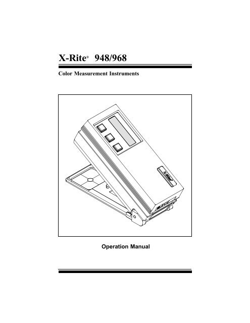
Dear Customer:Congratulations! We at X-<strong>Rite</strong>, Incorporated are proud to present you with anX-<strong>Rite</strong> Color Measurement Instrument. This instrument represents the very latest inmicrocontrollers, integrated circuits, fiber optics, and display technology. As aresult, your X-<strong>Rite</strong> 948/<strong>968</strong> is a rugged and reliable instrument whose performanceand design exhibit the qualities of a finely engineered instrument, which is notsurpassed.To fully appreciate and protect your investment, we suggest that you take thenecessary time to read and fully understand this manual. As always, X-<strong>Rite</strong> standsbehind your unit with a one year limited warranty, and a dedicated serviceorganization. If the need arises, please don’t hesitate to call us.Thank you for your trust and confidence.Ted ThompsonChairman and CEOi
Table of ContentsOpening Letter. . . . . . . . . . . . . . . . . . . . . . . . . . . . . . . . . . . . . . . . . . . . . . . . . . . . . . . . . . . . . . . . . . . . . iProprietary Notice . . . . . . . . . . . . . . . . . . . . . . . . . . . . . . . . . . . . . . . . . . . . . . . . . . . . . . . . . . . . . . . . . . iiiGeneral Description. . . . . . . . . . . . . . . . . . . . . . . . . . . . . . . . . . . . . . . . . . . . . . . . . . . . . . . . . . . . . . . . . ivUser Interface . . . . . . . . . . . . . . . . . . . . . . . . . . . . . . . . . . . . . . . . . . . . . . . . . . . . . . . . . . . . . . . . . . . . . viWhat To Do First! . . . . . . . . . . . . . . . . . . . . . . . . . . . . . . . . . . . . . . . . . . . . . . . . . . . . . . . . . . . . . . . . . . vii1. Getting Started . . . . . . . . . . . . . . . . . . . . . . . . . . . . . . . . . . . . . . . . . . . . . . . . . 11.1 Packaging Check list . . . . . . . . . . . . . . . . . . . . . . . . . . . . . . . . . . . . . . . . . . . 11.2 Shoe Lock . . . . . . . . . . . . . . . . . . . . . . . . . . . . . . . . . . . . . . . . . . . . . . . . . . . 31.3 Battery Charging . . . . . . . . . . . . . . . . . . . . . . . . . . . . . . . . . . . . . . . . . . . . . . 41.4 Applying Power . . . . . . . . . . . . . . . . . . . . . . . . . . . . . . . . . . . . . . . . . . . . . . 42. Positioning Techniques. . . . . . . . . . . . . . . . . . . . . . . . . . . . . . . . . . . . . . . . . . . 53. <strong>Operation</strong> . . . . . . . . . . . . . . . . . . . . . . . . . . . . . . . . . . . . . . . . . . . . . . . . . . . . . . 73.1 Keyswitch Descriptions. . . . . . . . . . . . . . . . . . . . . . . . . . . . . . . . . . . . . . . . . 73.2 Function Selection . . . . . . . . . . . . . . . . . . . . . . . . . . . . . . . . . . . . . . . . . . . . . 83.3 Illuminant/Observer Selection. . . . . . . . . . . . . . . . . . . . . . . . . . . . . . . . . . . . 103.4 Absolute Measurement . . . . . . . . . . . . . . . . . . . . . . . . . . . . . . . . . . . . . . . . . 123.5 Difference Measurement . . . . . . . . . . . . . . . . . . . . . . . . . . . . . . . . . . . . . . . . 133.5.1 Entry of Reference Values . . . . . . . . . . . . . . . . . . . . . . . . . . . . . . . . . . . . 143.5.2 Taking A Difference Measurement . . . . . . . . . . . . . . . . . . . . . . . . . . . . . 183.6 CMC Difference <strong>Operation</strong>. . . . . . . . . . . . . . . . . . . . . . . . . . . . . . . . . . . . . . 193.7 Measurement Averaging Procedure . . . . . . . . . . . . . . . . . . . . . . . . . . . . . . . 213.8 Store Data <strong>Operation</strong>. . . . . . . . . . . . . . . . . . . . . . . . . . . . . . . . . . . . . . . . . . . 233.9 Display Messages . . . . . . . . . . . . . . . . . . . . . . . . . . . . . . . . . . . . . . . . . . . . . 264. Calibration. . . . . . . . . . . . . . . . . . . . . . . . . . . . . . . . . . . . . . . . . . . . . . . . . . . . . 284.1 Positioning the Instrument on the X-<strong>Rite</strong> Calibration Standard . . . . . . . . . 294.2 Calibrating to a White Standard . . . . . . . . . . . . . . . . . . . . . . . . . . . . . . . . . . 325. Setting System Parameters . . . . . . . . . . . . . . . . . . . . . . . . . . . . . . . . . . . . . . . 355.1 Averaging. . . . . . . . . . . . . . . . . . . . . . . . . . . . . . . . . . . . . . . . . . . . . . . . . . . . 355.2 <strong>Operation</strong> Parameters . . . . . . . . . . . . . . . . . . . . . . . . . . . . . . . . . . . . . . . . . . 375.3 RS232 I/O Parameters. . . . . . . . . . . . . . . . . . . . . . . . . . . . . . . . . . . . . . . . . . 395.4 Format Output Parameters . . . . . . . . . . . . . . . . . . . . . . . . . . . . . . . . . . . . . . 416. Printing Data. . . . . . . . . . . . . . . . . . . . . . . . . . . . . . . . . . . . . . . . . . . . . . . . . . . 437. Changing Apertures . . . . . . . . . . . . . . . . . . . . . . . . . . . . . . . . . . . . . . . . . . . . . 478. Maintenance . . . . . . . . . . . . . . . . . . . . . . . . . . . . . . . . . . . . . . . . . . . . . . . . . . . 498.1 Troubleshooting. . . . . . . . . . . . . . . . . . . . . . . . . . . . . . . . . . . . . . . . . . . . . . . 498.2 Optics Cleaning . . . . . . . . . . . . . . . . . . . . . . . . . . . . . . . . . . . . . . . . . . . . . . . 508.3 Battery Replacement . . . . . . . . . . . . . . . . . . . . . . . . . . . . . . . . . . . . . . . . . . . 518.4 Target Window Replacement . . . . . . . . . . . . . . . . . . . . . . . . . . . . . . . . . . . . 528.5 Lamp Replacement . . . . . . . . . . . . . . . . . . . . . . . . . . . . . . . . . . . . . . . . . . . . 53AppendixA1 - Specifications . . . . . . . . . . . . . . . . . . . . . . . . . . . . . . . . . . . . . . . . . . . . . . . 54A2 - Optional Accessories . . . . . . . . . . . . . . . . . . . . . . . . . . . . . . . . . . . . . . . . . 55A3 - Factory Presets . . . . . . . . . . . . . . . . . . . . . . . . . . . . . . . . . . . . . . . . . . . . . . 56A4 - <strong>Spectrophotometer</strong> Stand . . . . . . . . . . . . . . . . . . . . . . . . . . . . . . . . . . . . . . 57A5 - Color Check . . . . . . . . . . . . . . . . . . . . . . . . . . . . . . . . . . . . . . . . . . . . . . . . 58ii
PROPRIETARY NOTICE: The information contained in this manual is derived from patentand proprietary data of X-<strong>Rite</strong>, Incorporated. This manual has been prepared expressly for thepurpose of assisting in the use and general maintenance of this instrument.Publication of this information does not imply any rights to reproduce or use this manual forpurposes other than installing, operating, or maintaining this instrument. No part of this manualmay be reproduced, transcribed, transmitted, stored in a retrieval system, or translated intoany language or computer language, in any form or by any means, electronic, magnetic,mechanical, optical, manual, or otherwise, without the prior written permission of an officer ofX-<strong>Rite</strong>, Incorporated.These provisions are intended to state all of the rights and responsibilities between X-<strong>Rite</strong>,Incorporated and the customer. They supersede all warranties, expressed or implied, andwhether of merchantability, fitness or otherwise. The remedies contained in this manual areexclusive. Customer and X-<strong>Rite</strong>, Incorporated waive all other remedies, including but notlimited to consequential damages.This instrument is covered by one or more of the following U.S. and foreign patents:U.S. patent #4,080,075, #4,591,978, and other patents pending.Copyright © 1990 by X-<strong>Rite</strong>, Incorporated"ALL RIGHTS RESERVED"Operating Keys2 x 16 Character DisplayTarget WindowRS232I/O PortSerial Number LabelAC AdaptorCharger JackLIMITED WARRANTY: X-<strong>Rite</strong>, Incorporated warrants each unit manufactured to be freeof defects in material and workmanship (excluding Ni-Cad batteries) for a period of twelvemonths. THERE ARE NO WARRANTIES OF MERCHANTABILITY OR FITNESS. THISWARRANTY OBLIGATION IS LIMITED TO SERVICING THE UNIT RETURNED TO X-RITE,INCORPORATED or AN AUTHORIZED SERVICE DEALER FOR THAT PURPOSE. The unitshall be returned with transportation charges prepaid. If the fault has been caused by misuseor abnormal conditions of operations, repairs will be billed at a nominal cost. In this case, anestimate will be submitted before work is started, if requested. Always include serial number inany correspondence concerning the unit. The serial number is located on the bottom housing.X-<strong>Rite</strong>, Incorporated offers a repair program for instruments out of warranty. For moreinformation, contact X-<strong>Rite</strong> Instrument Services Department.This agreement shall be interpreted in accordance with the laws of the State of Michiganand jurisdiction and venue shall lie with the courts of Michigan as selected by X-<strong>Rite</strong>,Incorporated.iii
General DescriptionThe X-<strong>Rite</strong> 948 is a reflection spectrocolorimeter. The 948 measures spectralreflectance from 400nm to 700nm in 20nm intervals. It has a 0° illumination angle,a 45° viewing angle, and features a dual-beam, single light pulse compensationmethod to insure accuracy.The 948 calculates and displays colorimetric data. In addition, the 948 can output(to a printer or computer) colorimetric data. An optional software package,ColorStart ® , can collect, sort, view, and analayze L*a*b* data using an IBM (or100% compatible) computer.The X-<strong>Rite</strong> <strong>968</strong> is a reflection spectrophotometer. The <strong>968</strong> measures spectralreflectance from 400nm to 700 nm in 20nm intervals. It has a 0° illumination angle,a 45° viewing angle, and features a dual-beam, single light pulse compensationmethod to insure accuracy.The <strong>968</strong> calculates colorimetric and spectrophotometric data. The <strong>968</strong> displayscolorimetric data, and can output (to a printer or computer) colorimetric and spectraldata. An optional software package, SpectroStart ® , can collect, sort, view, andanalayze L*a*b* and spectral data using an IBM (or 100% compatible) computer.The 948 and <strong>968</strong> measure spectral reflectance, absolute color or color difference,and absolute index or index difference for Whiteness and Yellowness.• XYZ or RGB & ∆XYZ or ∆RGB (CIE 1931 or RGB = X%Y%Z%)> Z% is one method used to measure paper brightness. Refer to Section 5.2 to activateRGB (X%Y%Z%).• Yxy & ∆Yxy (CIE 1931)• L*a*b* or Lab & ∆L*a*b* or Lab (CIE 1976 or HUNTER)• L*u*v* & ∆L*u*v* (CIE 1976)• L*C*h° & ∆L*C*H* (CIE 1976, ab, CMC, or uv)• Whiteness & Tint & ∆Whiteness & Tint (CIE & ASTM E313)• Yellowness & ∆Yellowness (ASTM E313 & ASTM D1925)The 948 and <strong>968</strong> have eight different CIE Illuminants for calculations undervarying lighting conditions. In addition, you can select the CIE 1931 2° Observer orthe CIE 1964 10° Observer.• Illuminant C• Illuminant D65• Illuminant D50• Illuminant A• Illuminant F2 (Cool White Fluorescent)• Illuminant F7 (Narrow-band White Fluorescent)• Illuminant F11 (TL84 / Wide-band Fluorescent)• Illuminant F12 (Ultralume 3000)iv
General Description . . . continuedTwenty four different reference values (Ref 01 - Ref 24) can be entered into the948 and <strong>968</strong> manually (numerically) or by measuring a reference sample. Theexceptions are that the reference values for ∆Whiteness and ∆Yellowness can onlybe entered by measurement. During reference entry all color spaces areautomatically updated when a change has been made in one of them.The 948 and <strong>968</strong> can function as color difference meters. By entering in yourreference (by measurement or numerically), the units will indicate the amount ofdifference between the reference and the measured sample.The store data feature allows the units to store up to five hundred measurementsfor transferring to a printer or computer (via RS232) at a later time.The CMC difference feature provides a single numeric value (∆ECMC) whichdescribes the color difference between a sample and a standard.The averaging feature allows the units to make several measurements from thesame and/or different locations on a sample or reference. This will allow for a betteroverall average of a color.The units are powered by six AA rechargeable batteries, or by the ACadaptor/charger provided. Additionally, the units retain calibration and referencevalues when turned off, or if the Ni-Cad batteries are discharged.X-<strong>Rite</strong>®, ColorStart®, SpectroStart®, and QA-Master® are registered trademarks of X-<strong>Rite</strong>, Incorporated.IBM is a registered trademark of International Business Machines Corp.Macintosh is a registered trademark of Apple Computer, Incorporated.All other logos, product names, registered trademarks, and trademarks mentioned are the property of their respective holders.v
User InterfaceThis section will familiarize you with the typographical conventions, displayfunctions, and general terms used in this manual.• In the text portion of this manual the <strong>968</strong> keys are shown with brackets onboth sides and in boldface. Ex., [FUNCTION], [ILLUM], and [DIF].• When a key is to be momentarily pressed, the statement "press" will be used.Ex., Press [FUNCTION].• When a key is to be held depressed until another action occurs, the statement"hold down" will be used. Ex., Hold down [ILLUM] until "SELECTILLUMINANT" is displayed.• Information that will appear in the displaywindow will be shown with quotationmarks on each side and in boldface. Ex.,"SELECT ILLUMINANT"SELECTILLUMINANTFUNCTION ILLUM DIFCAL• The symbols ▼ and ▲ represent theblue and red arrows on the <strong>968</strong>. Incalibration and reference value entry thearrows indicate which direction a valuecan be changed. Holding [DIF] depressedand pressing [▼ ] decreases the value and[▲ ] increases the value.X Y Z C2 X 4 . 1 2Y 2 . 8 7 Z 2 . 4 1FUNCTION ILLUM DIFCAL• The term "cursor" represents a blackrectangle that will blink next to or over avalue or function in the display. In mostcases it means that value is active and canbe altered via the [▼] and [▲] keys.• A "hand" indicates important notes andpossible operations that need to beperformed before the normal operation.• When a procedure is continued on the nextpage an arrow will appear in the bottomright hand corner of the page.WHTx . 3 0 9 0C 2CURSORY 8 5 . 5 5y . 3 1 8 1• Illuminant/observer combinations are expressed by special notations (Ex.,D65 2 indicates illuminant D, 6500°k, and 2° observer).vi
What To Do First!See how to unlock the shoe and charge the batteries...read Section 1 -Getting Started.See how the positioning of the instrument during measurement affects thereading...read Section 2 - Positioning Techniques.Calibrate your instrument...read Section 4 - Calibration.Setup your instrument. You can set the operating parameters, RS232parameters, and format output parameters of your unit. Remember, you canlock out of the display any function you do not want to use...read Section 5- Setting System Parameters.Learn the basic functions...read Section 3 - <strong>Operation</strong>.vii
1. Getting Started1.1 Packaging Check ListAfter removing the instrument from the shipping carton, inspect for possibledamage. If any damage is noted, contact the transportation company immediately.Do nothing more until the carrier’s agent has inspected the damage.If damage is not evident, check and make sure that all items are included (Referto the parts list below, and following page for the packaging illustration).Your unit was packaged in a specially designed carton to assure against damage.If reshipment is necessary, the instrument should be packaged in the original carton.If the original carton is not available, a new one can be obtained from X-<strong>Rite</strong> Inc.Refer to the packaging drawing on the following page (items 1, and 2).PACKAGING PARTS LIST1
PACKAGING2
1.2 Shoe LockThe shoe can be locked next to the housing for ease of storage.Unlocking Shoe1. Hold shoe [1] against unit.2. Slide black lock button [2] on bottom of unit towards the back until it stops, thenslowly release shoe [1].Locking Shoe1. Hold shoe [1] against unit.2. Slide black lock button [2] towards the front until it stops, then releaseshoe [1].[1][2]3
1.3 Battery Charging> THE UNIT SHOULD BE CHARGED BEFORE USE. The unit can be operated while thebatteries are being charged. Before using make sure the voltage indicated on the ACadaptor complies with the AC line voltage in your area. If not contact your X-<strong>Rite</strong> dealer.> The unit should be fully charged in 14 hours. Note: If your unit has not been used forseveral weeks recharge for approximately 24 hours.> Charging the batteries for less than 14 hours will reduce the operating time of the unit.> The best method to obtain the maximum battery life is to:- Always run the unit down to the point where the "BATTERIES LOW" message isdisplayed. Then charge the unit before the next message "CHARGE BATTERIES" isdisplayed.- Leaving the unit plugged into the AC wall outlet for extended periods of time (over 48hours) may shorten the battery life.- If you are going to store the unit for an extended period of time (over 6 months) youshould remove the Ni-Cad batteries from the unit.1. Plug the small connector end of the adaptor into back of unit.2. Plug the adaptor into AC wall outlet.ADAPTORWALL OUTLETSMALLCONNECTOR> This unit retains calibration, reference values, and all other data when the unit turns offafter 45 seconds of non-use (in battery operation), or if the Ni-Cad batteries aredischarged.1.4 Applying PowerDuring battery operation power is applied automatically when a measurement istaken or if a key is pressed. It automatically shuts off (within 45 seconds) if no keysare pressed or no further measurements are taken. The unit will not automaticallyshut off if the AC adaptor is connected.4
2. Positioning TechniquesThe variety of items that the 948 and <strong>968</strong> can measure is almost endless.However, in order to obtain accurate and repeatable measurements, the bottom ofthe shoe must be:• Parallel with the surface to be measured if the surface is flat.• Tangent to the surface to be measured if the surface is curved.The reason for this is that any movement during measurement can cause thereading to vary. To obtain the most accurate and repeatable measurements, there area few guide rules you can follow.If the item to be measured is smaller than the shoe, you may want to make aplatform (the same height of the item) for the instrument to sit on. If the item tomeasure is curved, you may want to make a jig for the item to rest in.Shown below and on the next page are some examples of methods used toaccomplish this. Example 1 shows a platform for measuring a paint chip. Example2 shows a jig being used to measure a cup. Example 3 shows a jig being used formeasuring a small knob.Note: A mounting fixture (jig) is available from X-<strong>Rite</strong> (P/N <strong>968</strong>-80). The jig canmeasure objects that are a maximum of 4" inches in width, or 2" to the center of theobject. Refer to Appendix A-4 for further information about this mounting fixture.Example 1- Measuring a Paint ChipCORRECTPaint ChipPlatformINCORRECT5
Example 2 - Measuring a Coffee CupCoffee CupJigCORRECTExample 3 - Measuring a SmallJigKnobCORRECT6
3. <strong>Operation</strong>3.1 Key DescriptionsFUNCTION ILLUM DIFCAL[FUNCTION]/[▼]• Selects the function that will be used for measurement. Eachmomentary depression will cause the display to page through XYZ,Yxy, L*a*b*, L*u*v*, L*C*h°, Whiteness, & Yellowness.• Decreases numeric values when used with the [DIF] key duringentry of reference or calibration values.• Selects Calibration when pressed with [ILLUM] key.• Selects various steps when in system setup procedures.[ILLUM]/[▲]• When held depressed activates illuminant/observer selection,thereafter, momentary depressions select the illuminant to beused. The available illuminants are:See Section3.24.04.05.03.3CAF2F7D 65 D 507F11F12Note: the [DIF] key selects the Observer (CIE 1931 2° or CIE 196410°) to be used.• Increases numeric values when used with [DIF] key during entryof reference or calibration values.• Displays the reference number when pressed momentarily.• Selects Calibrate when pressed with the [FUNCTION] key.[DIF]/[▼▲]• When at function level, toggles Delta (∆) On and Off with eachdepression. Delta being the difference mode.• Decreases reference or calibration values when used with the[FUNCTION] key.• Increases numeric values when used with the [ILLUM] key.4.03.54.03.54.04.0
The illuminant/observer will not be displayed in the difference mode during operation ofthat function. It is only displayed during function selection.> ∆ E will be displayed in place of ∆ L*a*b*, ∆ L*u*v*, and ∆ L*C*H* during differenceoperation.ILLUMINANTNOT DISPLAYEDY E L Y e + 3 3 .5 6Yd + 8 7 .9 7W H T W e- 1 . 3 7W + 9 7 . 8 7 T - 1 1 5 . 8COREL 2 3 . 4 5.E 41.89 +C 2 0 . 7 8 H + 2 5 . 7 9.DELTA E.E 23.67u + 2 2 . 4 6.E 15.98a + 1 8 . 5 9.L + 1 2 . 3 3v + 6 . 8 9.L + 2 3 . 4 8b + 8 . 7 5Y x y Y + 3 .2 4x + . 2 8 9 0 y + .3 6 4 5X Y Z X + 4 .1 2Y 2 . 8 7 Z + 2 .4 19
3.3 Illuminant/Observer SelectionThere are eight different illuminants and two observers to choose from.1) To enable illuminantselection: Hold down[ILLUM] until "SELECTILLUMINANT" is displayed.SELECTILLUMINANTC 2X Y ZX 4 . 1 2Y 2 . 8 7 Z 2 . 4 1FUNCTION ILLUM DIFCALHOLD2) The active illuminant &observer are displayed.Press [ILLUM] to select adifferent illuminant.Note: Illuminant F2 representsa cool white fluorescent lamp.F122F11F7 2F2 2A 2D502652UltralumeTL84broad bandcool whiteD 2 PRESSIlluminant F7 represents abroad-band daylight fluorescentlamp.Illuminant F11 represents anarrow-band white fluorescentlamp (or illuminant TL84).C 2exit illm obsFUNCTION ILLUM DIFCALIlluminant F12 representsUltralume 3000.Press [DIF] to select adifferent observer.C 10C 2exit illm obsFUNCTION ILLUM DIFCALPRESS10
Illuminant/Observer Selection...continued3) To exit press [FUNCTION].When "Function Key" is pressed,the instrument will automaticallyconvert the stored spectralreferences (if any) to tristimulusfor the different illum/obsselected. The unit will also ask ifyou would like the references tobe cleared. If you do not want thereferences cleared (or you do nothave any entered), disregard theprocedure below.exitC 10X Y ZX 4 . 0 8Y 2 . 8 1 Z 2 . 3 7UPDATING REFS # 1-24CLEAR REFSFUNCTION ILLUM DIFCALillmobsC 10 PRESSClearing ReferencesThe "Clear Reference" function isuseful if the Illum/Obs is beingchanged often, and manyreferences exist in the instrumentthat are not being used. This willenable the operator to speed upthe time it takes the instrument torecalculate to a differentillum/obs.Press [DIF] to enter clear referencefunction. After the "Dif Key" ispressed "CLEAR REFERENCES↓NO YES↓" is displayed. Press[DIF] to clear or [FUNCTION] notto clear.> You must press the "Dif" keywhile the unit is recalculatingthe references to activate thisfunction.> If the clearing procedure iscarried out, all references(measured & numericallyentered) will be removed.> Refer to Section 3.5 for a moredetailed explanation onmeasured and numericallyentered references.11
3.4 Absolute MeasurementsThe 948 and <strong>968</strong> can perform absolute measurement in XYZ (RGB), Yxy,L*a*b*, L*u*v*, L*C*h°, Whiteness, & Yellowness.> Helpful Hint: If you are going to measure something like a textile, you will receivebetter results if you use the averaging function (see Section 3.6). Also, while measuringa textile, take several measurements in a circular format.> If the ∆ is displayed, press [DIF] to activate absolute mode.> If the desired illuminant/observer is not displayed, refer to Section 3.3.1) Press [FUNCTION] to selectdesired measurement space.X Y Z C 2 X 4 . 1 2Y 2 . 8 7 Z 2 . 4 1FUNCTION ILLUM DIFCALPRESS2) Center the target windowover the area to be measured.TARGET WINDOW3) Lower unit to target windowand hold compressed."READING XYZ C 2 " (i.e., theselected function & theillum/obs) will momentarilybe displayed, and then thedata.Release unit after data isdisplayed.X Y Z C 2 X 1 . 2 4Y 3 . 3 6 Z 4 . 1 8READING XYZ C 24) The display will show theabsolute values for XYZ.FUNCTION ILLUMINANT X VALUEX Y Z C 2 X 1 . 2 4Y 3 . 3 6 Z 4 . 1 812Y VALUEZ VALUE
3.5 Difference MeasurementThe 948 and <strong>968</strong> can measure the difference between a sample color and areference. In order to measure these differences the reference must first be enteredinto memory. There are 24 different locations to store references.The reference can be entered numerically using the key pad, or by measuring thereference color.> The ∆Whiteness and ∆Yellowness reference color can only be entered by measurement.Reference (Measurement)Measured references are stored spectrally and the tristimulus values arerecalculated each time a different illum/obs is selected. As long as references aremeasured, the instrument can automatically convert the spectral data to allow forviewing of difference measurements under various illum/obs sets.Reference (Numeric)Numerically entered references are saved with the selected illum/obs. A total of 7sets of numerically entered tristimulus values (with different illum/obs) can bestored in each reference location.If a different illum/obs is selected and no numerically entered reference supportsthat illum/obs, the instrument will turn "OFF" that reference location.The instrument can not recalculate to a different illum/obs if it was not previouslyentered during numeric reference entry.<strong>Operation</strong> ModeThe instrument can be set to operate in an automatic mode, where it willautomatically select the closest reference; or in manual mode, where you have tomanually select the reference locations you want to use. Refer to Section 5.2,Setting <strong>Operation</strong> Parameters for information on selecting manual or automaticreference operation.In automatic mode, the instrument will select the reference that is closest to themeasured color. If by some chance it is not the correct reference, simply press the[ILLUM] key twice and the unit will select the next closest reference.In manual mode, you mustmanually select the reference.Once you have selected areference, that reference will beused until you select a differentreference.To activate the Differencemode, press [DIF] and the ∆ signwill appear in the display. The∆Functions will have a "+" signin front of them for positivevalues instead of being impliedas in the absolute function.> ∆L*a*b*, ∆L*u*v*, & ∆L*C*H* show ∆E in function location.13DELTA SIGNX Y Z X + 4 . 1 2Y + 2 . 8 7 Z + 2 . 4 1C 2X Y ZX 4 . 1 2Y 2 . 8 7 Z 2 . 4 1FUNCTION ILLUM DIFCALPRESS TO TOGGLE DIFFERENCE(DELTA) ON & OFFPLUS SIGNDELTA ONDELTA OFF
Difference Measurement...continued> When entering references with any illuminant other than C 2 , Yellowness and Whiteness(per ASTM E313) are not calculable.> Once a reference has been set, changing between CIE Lab or Hunter Lab; Lch (ab) orLch (uv); and XYZ or X%Y%Z%, the references will not be automatically adjusted.Note: You can set all reference locations to OFF by:•Activating difference mode.•Hold down [DIF] until reference entry is activated, then simultaneously press[ILLUM] and [FUNCTION].Ref 1 defaults to ON if all references are turned OFF.Refer to Steps 2 and 3 below.3.5.1 Entry of Reference ValuesBy Measurement1) Select desired Illum/Obs (seeSec. 3.3).2) Press [FUNCTION] to selectdesired measurement space.> If ∆ is not displayed, press[DIF] to activate Differencemode.PRESSC 2X Y Z X + 4 . 1 2Y + 2 . 8 7 Z + 2 . 4 1FUNCTION ILLUM DIFCAL3) Hold down [DIF] until "SETREF VALUES - ENTER orMEASURE" is displayed.First displayed are theprevious entered referencevalues for the last selectedreference location.EXITY 4 . 4 5REF 03Y 4 . 4 5XYZY 4 . 4 5C 2X 6 . 1 6Z 2 . 6 9X 6 . 1 6Z 2 . 6 9X 6 . 1 6Z 2 . 6 9The reference location ismomentarily displayed.Then "EXIT" is displayed.> You can set all referencelocations to OFF by: holdingdown [DIF] thensimultaneously pressing[ILLUM] and [FUNCTION].Note, Ref 1 defaults to ON.SET REF VALUESENTER or MEASUREFUNCTION ILLUM DIFCALHOLD DOWN14
Entry of Reference values - By measurement . . . continued4) Select the reference location.If the cursor is not blinkingnext to the reference location,press [DIF] until it does.Hold down [DIF] and press [▼]to decrement thru the referencelocations or press [▲] toincrement.CURSORREF 03Y 4 . 4 5FUNCTION ILLUM DIFCALDECREMENTREFERENCE SPACEINCREMENTX 6 . 1 6Z 2 . 6 9++5) Measure the reference color.REF 03Y 4 . 4 5C 2X 6 . 1 6Z 2 . 6 9READING XYZ 2 CReference Color6) Press [FUNCTION] and [ILLUM]at the same time to exit to themain menu."REFERENCES UPDATED" ismomentarily displayed and theprocedure is finalized.> If no measurement or entry ismade the unit will display"REFERENCES - NOTCHANGED."EXIT X 4 . 1 2Y 2 . 8 7 Z 2 . 4 1FUNCTION ILLUM DIFCALPRESS AT SAME TIME15
Entry of Reference Values...By Numeric Entry> Whiteness & Yellowness reference values can not be entered via the keyboard.1) Select desired Illum/Obs (seeSec. 3.3).2) Press [FUNCTION] to selectdesired measurement space.> If ∆ is not displayed,momentarily press [DIF] toactivate Difference mode.PRESSC 2X Y Z X + 4 . 1 2Y + 2 . 8 7 Z + 2 . 4 1FUNCTION ILLUM DIFCAL3) Hold down [DIF] until "SETREF VALUES - ENTER orMEASURE" is displayed.The unit will first display theprevious entered referencevalues for the last selectedreference location.The reference location ismomentarily displayed.Then "EXIT" is displayed.EXITY 4 . 4 5REF 03Y 4 . 4 5XYZY 4 . 4 5C 2X 6 . 1 6Z 2 . 6 9X 6 . 1 6Z 2 . 6 9X 6 . 1 6Z 2 . 6 9SET REF VALUESENTER or MEASUREFUNCTION ILLUM DIFCALHOLD DOWN4) Select the reference location.If the cursor is not blinkingnext to the referenceslocation, press [DIF] until itdoes.Hold down [DIF] and press[▼] to decrement thru thereference locations or press[▲] to increment.CURSORREF 03Y 4 . 4 5REFERENCE SPACEX 6 . 1 6Z 2 . 6 9FUNCTION ILLUM DIFCALDECREMENTINCREMENT++16
Entry of Reference values - By Numeric Entry . . . continued5) The cursor will blink over theactive value that can beedited. Enter the numbers foreach value.•The [DIF] key advances thecursor to the next value to beedited.•The [DIF] key is used inconjunction with [▼] todecrease and [▲] to increasethe value. Note: Hold [DIF]depressed then press either[▼] or [▲] to change value.REF 03Y 2 . 8 7FUNCTION ILLUM DIFCALX 4 . 1 2Z 2 . 4 1DECREASE INCREASE +CURSOR+ADVANCE6) Press [FUNCTION] and [ILLUM]at the same time to exit to themain menu."REFERENCES UPDATED" ismomentarily displayed and theprocedure is finalized.EXIT X 4 . 1 2Y 2 . 8 7 Z 2 . 4 1FUNCTION ILLUM DIFCAL> If no measurement or entryis made the unit will display"REFERENCES - NOTCHANGED."PRESS AT SAME TIME17
3.5.2 Taking A Difference Measurement> If the ∆ is not displayed, press [DIF] to activate difference mode.> The reference color must first be entered into memory, refer to Section 3.5.1.> If reference selection is not set to auto, select the correct reference location beforefollowing the procedure below (refer to Section 3.5.1).> If the desired illuminant/observer is not displayed, refer to Sec. 3.3.1) Press [FUNCTION] to select desiredmeasurement space.X Y Z C 2 X + 4 . 1 2Y + 2 . 8 7 Z + 2 . 4 1FUNCTION ILLUM DIFCALPRESS2) Center target window over area tobe compared.SAMPLE AREATO BECOMPARED3) Lower unit to target window andhold compressed. "READING XYZC 2 " (i.e., the selected function andillum/obs) will momentarily bedisplayed, and then the referencelocation and data.REF 03 X + 2 . 8 2Y + . 8 8 Z + . 4 8READING XYZC 2Release unit after data isdisplayed.4) The display will show thedifference between the referencecolor and the area measured.> If L*a*b*, L*u*v*, or L*C*H* areselected, ∆E value will bedisplayed in place of theFunction & Illuminant.> If you want to display theselected reference location,press [ILLUM].FUNCTION ILLUMINANT X VALUEX Y Z C 2 X + 2 . 8 2Y + . 8 8 Z + . 4 8Y VALUEZ VALUEORDELTA E VALUEE 2 . 9 9 L + 2 . 8 2a + . 8 8 a + . 4 818
3.6 CMC Difference <strong>Operation</strong>CMC is an ellipsoidal tolerancing method which attempts to correlate smallmeasured color differences with visual assessment.CMC provides a single numeric value (∆ECMC) which describes the colordifference between a sample and a standard. This allows the use of a singletolerance value for comparing the acceptability of a color match.∆ECMC is derived from the following formula:L C = ∆LS Lι∆Ec = [LC 2 + CC 2 + HC 2 ] 1/2C C = ∆CcS LH C = ∆HS HThe CMC reference menu consists of the three factors that can be set: Lightnessfactor (ι), Chromaticity factor (c), and Commercial factor.• The lightness factor is normally set to 2.00 (default) but other values may berequired when surface characteristics differ dramatically.• The chromaticity factor normally does not require any adjustment from thedefault setting of 1.00.• The commercial factor is the tolerance limit that each sample is not to exceed.(e.g., if cf= 1.00 then any sample which has a ∆ECMC value greater than 1.00would be commercially unacceptable.)To Setup CMC Difference:> CMC Option is only available on L*C*H* difference function.> CMC option must first be selected in <strong>Operation</strong> Parameters (Sec. 5.2).1) Follow Step 1 through 5 in Section 3.5.1 for entering a reference manually or bymeasurement.2) Press [DIF] until the CMC menu isdisplayed. The cursor will blinkover the active value that can beedited. Enter the number for eachvalue.•The [DIF] key advances thecursor to the next value to beedited.•The [DIF] key is used inconjunction with the [▼] todecrease and [▲] to increase thevalue. NOTE: Hold [DIF]depressed then press either [▼] or[▲] to change values.19CHROMATICITYFACTORCURSORREFERENCE SPACEREF 01 l 2 . 0 0c 1 . 0 0 cf = 1 . 0 0FUNCTION ILLUM DIFDECREMENTLIGHTNESSFACTORCALINCREMENTCOMMERCIALFACTOR++
CMC Difference <strong>Operation</strong>...continued3) Press [FUNCTION] and [ILLUM]at the same time to exit to the mainmenu."REFERENCES UPDATED" ismomentarily displayed and theprocedure is finalized.> If no measurement or entry ismade the unit will display"REFERENCES NOT CHANGED."EXIT l 2 . 0 0c 1 . 0 0 cf = 1 . 0 0FUNCTION ILLUM DIFCALPRESS AT SAME TIMETaking a CMC Difference MeasurementBefore a CMC difference measurement can be made:• LCh CMC must be set to "ON" in modes (Sec. 5.2)• Reference must be entered (Sec. 3.5.1)• CMC difference operation must be setup (Sec. 3.6).1) Select desired illuminant/observer (see Sec. 3.3).2) Select L*C*h° difference mode function.3) Center target window over area to be compared.4) Lower unit to target window and hold compressed. "Reading LcCcHc C 2 " (i.e.,the selected illum/obs) will momentarily be displayed, and then the referencelocation and data. Release the unit.5) The display will show the differencebetween the reference color andsample, and the ∆ECMC value.•Pressing the [DIF] key will togglethe display between the absolutemeasurement values and the CMCdifference values.CMC Difference ValuesAbsolute> "CMC cf TOLERANCEEXCEEDED" will display during a L*C*h° difference measurement when DECMC valueexceeds the cf (commercial factor) value.> LcCcHc are values used for calculating ∆Ecmc and are not ∆L*, ∆C*, and ∆H*.20
3.7Measurement Averaging ProcedureWhen averaging is activated in setup, averaging operation will occur on absolutemeasurements, reference entry measurements, and difference measurements.There are two averaging methods that are used: (refer Sec. 5.1 to activateaveraging):• SAMPLES AVERAGED - allows you to enter the number of measurements youwill make (1-99) at various locations on a sample, to obtain an average value.• SUB AVERAGE - allows you to enter the number of measurements the unitwill take (1-6) on a sample at a single location, to obtain an average value.> When average and sub average are set to one, no averaging is performed and noaveraging messages will be displayed.The following example was taken in the absolute measurement mode using: XYZfunction, two sub averages, and two measurement averages.1) Press [FUNCTION] to select XYZmeasurement space.X 4 . 1 2Y 2 . 8 7 Z 2 . 4 1X Y Z C 2 2 OF 2FUNCTION ILLUM DIFCALPRESS2) Center the target window over firstarea on the sample to be measured.TARGETWINDOW3) Lower unit to target window andhold compressed. "READING XYZC 2 1 OF 2", "2 OF 2", and the datais display.After releasing the read head,"MEASURE SAMPLE 2 OF 2" isdisplayed.MEASURE SAMPLEXYZ C 2 X 63.90Y 65.03 Z 23.02READING XYZ C 22 OF 2READING XYZ 2 C1 OF 221
Measurement Averaging Procedure . . . continued4) Center the target window oversecond area on the sample tomeasure.TARGETWINDOW5) Lower unit to target window andhold compressed. "READING XYZC 2 1 OF 2" and "2 OF 2" willmomentarily be displayed, andthen the averaged data.X Y Z C 2 X 63.91Y 65.04 Z 23.02AVERAGECALCULATEDREADING XYZ2C2 OF 2READING XYZ2C1 OF 26) The display will show the averageabsolute values for XYZ.FUNCTION ILLUMINANT X VALUEX Y Z X 63.91C 2Y 65.04 Z 23.02> Do not jar or lift reading headduring sub averagingmeasurements.> Refer to Section 5.1 averagingsetup procedure.> When averaging is activated, thisbasic procedure must also befollowed during referencemeasurements and differencemeasurements.Y VALUEZ VALUE22
3.8 Store Data <strong>Operation</strong>The data storage feature allows the unit to store measurement data for up to 500readings. (Refer to Sec. 5.4 to activate.)There are four basic operations of the store data function that can be utilized inthe store data function.• Group Selection - group tagging allows you to assign group numbers to thestored values. Group tagging is only accessable through RCI with a softwarepackage such as SpectroStart.• Send data - allows all of the stored data to be transferred to a computer orserial printer. Data is sent as determined by the function displayed and modesenabled.• Delete last - allows only the last measurement data to be deleted from storedmemory.• Clear all - causes all of the measured data in stored memory to be deleted.The following sample (made in XYZ absolute) illustrates the different functionsof the data storage feature.MEASUREMENT1) Press [FUNCTION] to select XYZmeasurement space.X Y Z C 2 X 4 . 1 2Y 2 . 8 7 Z 2 . 4 1FUNCTION ILLUM DIFCALPRESS2) Measure first sample."READING XYZ C 2 " is momentarilydisplayed, then the measurement.Upon release of the read head,"DATA STORED 1 OF 500" and thenthe measurement is displayed.XYZ C 2 X 3.41Y 3.47 Z 4.25DATA STORED1 OF 500XYZ C 2 X 3.41Y 3.47 Z 4.25READING XYZ 2 C23
Store Data <strong>Operation</strong> . . . continued3) Measure second sample."READING XYZ C 2 " is momentarilydisplayed, then the measurement.Upon release of the read head,"DATA STORED 2 OF 500" and thenthe measurement is displayed.XYZ C 2 X 3.45Y 3.52 Z 4.29DATA STORED2 OF 500XYZ C 2 X 3.45Y 3.52 Z 4.29READING XYZ C2SEND DATA4) Press both [ILLUM] and [DIF] at thesame time.XYZ C 2 X 3.45Y 3.52 Z 4.29FUNCTION ILLUM DIFCALPRESS AT SAME TIME5) Press [DIF] to transfer data (go toStep 7).If "NO" is selected, press[FUNCTION] and advance to Step 6.Sample PrintoutDATA TRANSFERCOMPLETETRANSMITTING2 OF 2TRANSMITTING1 OF 2SEND DATA ?NO 2 YESNEXTSTEPPRESS24
Store Data <strong>Operation</strong> . . . continuedDELETE LAST MEASUREMENT6) Press [DIF] to delete the lastmeasurement made (this step canbe repeated to delete several of thelast measurements).If "NO" is selected, press[FUNCTION] and advance to Step 7.DELETE LAST ?NO 1 YESLAST DELETEDDELETE LAST ?NO 2 YESNEXTSTEPPRESSNumber of Measurements StoredCLEAR ALL DATA7) Press [DIF] to clear all storedmeasurement data taken.If "NO" is selected, press[FUNCTION] to return to normaloperation.> The Send/Clear data function maybe exited at anytime by pressing[FUNCTION] and [ILLUM] at thesame time.> Refer to Section 5.4 to activatethe store data function.> "STORAGE FULL" will display onall measurements after 500 storedmeasurements has been reachedNORMALOPERATION2XYZ C X 3.45Y 3.52 Z 4.29DATA CLEAREDCLEAR ALL ?NO 2 YESPRESS25
3.9 Display MessagesThe most likely reasons for error messages to display are described below. If anerror message is consistently displayed, contact X-<strong>Rite</strong> or an Authorized ServiceCenter.Power-Up Messages"MEMORY LOST" is displayed when the instrument determines that the data in the(battery backed up) RAM has been corrupted, if the internal lithium battery onthe P.C.B. is bad, or if a new EPROM has been installed.<strong>Operation</strong>al Messages"CMC cf TOLERANCE EXCEEDED" is displayed during a L*C*h° differencemeasurement when ∆E CMC value exceeds the cf (commercial factor) value."C 2 ONLY FOR - YELLOWNESS" is displayed when trying to select anilluminant other than C 2 for Yellowness."INVALID READING" is displayed when the unit is not held down long enoughduring a measurement."NEED CALIBRATION" is displayed if the calibration procedure is not performedfor 24 hours, or if there is a 10°C change in temperature since the last calibration."READING COMPLETE" measurement has been taken and the instrument can be released."READING XYZ C 2 " is displayed during a measurement. XYZ can be any of thefunctions and C 2 can be any of the illum/obs combinations."REFERENCES - NOT CHANGED" is displayed after leaving the Reference Entryfunction, and no change was made."REFERENCES UPDATED" is displayed when [FUNCTION] and [ILLUM] aresimultaneously pressed, when exiting reference mode."SELECT ILLUMINANT" is displayed when the [ILLUM] key is held down for threeseconds, activating illuminant selection."SET REF VALUES - ENTER or MEASURE" is displayed if the difference modeis on, and the [DIF] key has been held down for three seconds, activatingreference entry mode."SET REF VALUES - MEASURE ONLY" is displayed in ∆WHT and ∆YEL whenreference entry mode is enabled. You can only enter these reference values bymeasurement."UPDATING REFS ## - CLEAR REFS↓" when the illuminant/observer ischanged the stored references are automatically updated. This message alsoallows you to clear out all stored references (see Section 3.3 for more details)."USE ANOTHER COLOR SPACE" is displayed when you try to enter thereference value numerically in ∆WHT and ∆YEL. You can only enter thereference values by measurement.Calibration Messages"CALIBRATION - FAILED" is displayed when making a calibration measurementand something is wrong (invalid reading or data is out of range).26
Display Messages . . . continued"CALIBRATION - NOT CHANGED" is displayed when the user decides to terminatethe calibration procedure by simultaneously pressing [FUNCTION] and [ILLUM]."CALIBRATION - UPDATED" is displayed after the calibration procedure has beensuccessfully completed."CAL ERROR ### - CELL CHANGE" make sure that calibration plaque is clean andinstrument is positioned exactly on the white spot. If the error persists, the numberthat is displayed should be reported to X-<strong>Rite</strong> or an authorized service center."CAL ERROR ### - MOTION DETECTED" calibration requires that theinstrument remain motionless during the five measurements of the white spot. Ifthe error persists and is not due to movement, the number that is displayedshould be reported to X-<strong>Rite</strong> or an authorized service center."INVALID ENTRY" is displayed when the numbers entered for the white values areinappropriate."INSUFFICIENT READINGS" indicates that all sub-average readings were not made.Miscellaneous Messages"BATTERIES LOW" indicates that the batteries are getting low and will soon needto be charged. It will only be displayed while the measurement is in progress.Once displayed you will have approximately 100-200 measurements remainingbefore charging is mandatory."BATTERIES MUST - BE CHARGED" indicates that the batteries are too low tooperate the unit. It will be displayed until you begin the recharge cycle,thereafter, the unit will be functional and all previous data will be accessible."I/O NOT READY - check I/O PIN 5" is displayed when I/O pin 5 is set to "CTS"in modes and the unit is not connected to a printer or computer. Set handshaketo "OFF" if unit is not connected to a printer or computer."LAMP FAILURE" measurement lamp is bad. The lamp should be replaced byX-<strong>Rite</strong> or an authorized X-<strong>Rite</strong> service center. When this message occurs, youcan get out of this condition by pressing [FUNCTION] then [ILLUM]then [FUNCTION]; or waiting until the unit powers down."READING ERROR ##" reading error due to hardware problem. If this messagepersists the number that is displayed should be reported to X-<strong>Rite</strong> or anauthorized service center."REFL. EXCEEDED" calculation of reflectance for at least one of the 20nmsegments was more than 200%. This is usually caused by a bad calibrationprocedure. Recalibrate unit."THANKS! - I NEEDED THAT!" indicates that the charger has been plugged in andthe batteries are being charged. This is in response to the message"BATTERIES MUST BE CHARGED"."WEAK LAMP - REPLACE SOON" indicates that the lamp is getting weak andshould be replaced in the near future. When this message occurs, you can getout of this condition by pressing [FUNCTION] then [ILLUM] then [FUNCTION]; orwaiting until unit powers down."X-<strong>Rite</strong> VER#### - COPYRIGHT 1990" is displayed when first activatingcalibration. #### represents the datecode of the software.27
4. CalibrationThe 948 & <strong>968</strong> should be calibrated to the X-<strong>Rite</strong> standard the first thing each dayand every four hours of operation thereafter. However, a "NEED CALIBRATION"message will appear in the display:•If the calibration procedure has not been performed for 24 hours.•If there is a 10°C change in temperature since the last calibration.•If zero reflectance is measured improperly.•If the lamp output changes.Whenever this message appears the calibration procedure should be performedbefore another measurement is taken to ensure accuracy.Important Calibration Notes• If you change apertures you must change the aperture setting, read zeroreflectance, & calibrate the unit (see Section 4.2, steps 1, 2, & 5a thru 5d).• Dirt or dust in the optics area will cause an inaccurate calibration reading.Refer to Section 8.2 for the optics cleaning procedure.• The ceramic Reflection Standard is dramatically affected by smudgemarks, dust, and finger prints. The standard should be cleaned using a mildsoap and warm water solution, thoroughly rinsed with warm water, and wipeddry with a lint free cloth. You must let the standard dry completely beforetaking a calibration reading.• If you are having linearity problems it’s possible that there is dust in theoptics or Zero Reflectance has drifted. If you improperly measure ZeroReflectance the unit can not automatically detect the drift. If you suspect thisis the case, you should manually activate Read Zero Reflectance byperforming Steps 1, 2, & 5 of Section 4.2.• Do not move the 948/<strong>968</strong> while taking a calibration measurement. If motionis detected an error message will be displayed and calibration aborted.28
4.1 Positioning the <strong>968</strong> Onto the X-<strong>Rite</strong> StandardYou must set the 948/<strong>968</strong> on the white standard so that the maximum amount ofthe bottom rubber pad of the shoe resides on the standard, and the target is centeredon the circle. If you do not, the unit may rock slightly and cause an erroneous readingof the standard.1) Center the target window on the White circle, making sure that the rubber pad iscompletely on the standard and is down flat.BOTTOM VIEW2) Take the measurement.29
Shown below is an IMPROPER METHOD of measuring the standard.BOTTOM VIEWINCORRECT!30
X-<strong>Rite</strong> Reflection StandardX-<strong>Rite</strong>Reflection StandardP/N <strong>968</strong>-62Serial No. CXXXXXXXP-XXXXXDate XX/XX/XXWAVE[nm]390400410420430440450460480500520540560580600620640660680700710REFL[%]62.1076.7081.8885.0285.9986.1286.4886.7487.0587.4287.3687.0886.7286.2585.7185.1884.5284.0283.3582.6981.99L*a*b*CALIBRATIONCHECKC/2 (WHITE)Instrument Model No.Instrument Serial No.COLOR CHECKRefer to section in operation manualappendix for procedure to obtainreference values.DATE:ILLUM/OBS:TEMP:APERT:REFERENCES VALUESSTEP1 (White)2 (Blue)3 (Brown)L* a* b*Notes:®IMPORTANT!The standard is dramatically affectedby smudge marks and dust; and mustbe kept clean.The Calibration Values for the white spot are affected by the environmentand cleaning method of the standard.If the white spot does not measure correctly, it could be that the unitneeds to be calibrated; there is dust in the optics; or the standard hassmudge marks or is dirty.The ceramic standard should be cleaned using a mild soap and warmwater solution, thoroughly rinsed with warm water, and wiped dry with aclean, lint free cloth.If you lose your envelope, you can obtain the calibration values from theback page of this manual, or, by looking at them in the calibrationprocedure. Otherwise, you can contact X-<strong>Rite</strong> with the serial number ofyour standard and get the values.31
4.2 Calibrating to the White Standard> If you are changing aperture size: Do steps 1, 2, & 5a thru 5d. Skip steps 3 & 4.1) Press both [FUNCTION] and[ILLUM] at the same time.C 2X Y ZX 4 . 1 2Y 2 . 8 7 Z 2 . 4 1FUNCTION ILLUM DIFCALPRESS AT SAME TIME2) Select "YES", press [DIF].The copyright and softwareversion are momentarilydisplayed.X-<strong>Rite</strong>Ver XXXXCopyright 1990CALIBRATE ?NOYESFUNCTION ILLUM DIFCALPRESS3) "READ CAL WHITE" is displayed.At this point you have twooptions:• You can measure the whitespot on the standard (go tostep 4). This is standardoperating procedure.READ CAL WHITEFUNCTION ILLUM DIFCAL5SECREAD CAL WHITEEXITCHANGE• Or, you can press [CHANGE]to change the calibrationvalues for the 21 differentspectral values or to changethe aperture setting. Thisprocedure is only usedwhen you want tocalibrate to a differentstandard or you changeapertures. Go to step 6.32
Calibrating to a White Standard . . . continued4) Measure the WHITE patch on thestandard. You must hold the unitdepressed until all five readingshave been completed.> You must set the unit on thestandard so that the maximumamount of the bottom rubber padof the shoe resides on thestandard (refer to Section 4.1)."CAL READING 1 OF 5" thru "CALREADING 5 OF 5" is displayed; then"CALIBRATION UPDATED." Theprocedure is finalized and theunit returns back to main menu.> During the Cal Reading, the readhead must remain down andstable or an error message mayoccur.> If "PLEASE WAIT XX (1-30)SECONDS" is displayed duringcalibration, continue to hold readhead down until calibrationreadings are over. This will onlyoccur if the calibration procedureis performed within 30 seconds ofa previous measurement.> If "READ ZEROREFLECTANCE" is displayedafter reading the white spot, goto step 5. This will only occur ifthe calibration values for zeroreflectance have drifted.WHITECALIBRATIONUPDATEDCAL READING5 OF 5CAL READING4 OF 5CAL READING3 OF 5CAL READING2 OF 5CAL READING1 OF 5THE FOLLOWING STEPS (5 & 6) ARE ONLY NECESSARY IF YOU WANT TO MEASUREZERO REFLECTANCE, CHANGE SPECTRAL VALUES, or CHANGE APERTURE SIZE.5) Steps 5a - 5d are only necessary if "READ ZERO REFLECTANCE" is displayed,you want to manually activate Zero Reflectance Measurement, or YOU WANT TOCHANGE APERTURE SIZE.Zero Reflectance is defined as, "measuring air with no ambient light".This can be accomplished by holding the unit depressed (take a reading) in adark room. In some cases, it is possible to just take a reading under a desk withno direct light.To manually activate zero reflectance measurement or you want tochange aperture size, see next page.33
Zero Reflectance/Aperture size Setting . . . continued5a) Press [CHANGE].READ CAL WHITEEXITCHANGEFUNCTION ILLUM DIFCALPRESS5b) Press [NO].NEW CAL VALUES?NOYESFUNCTION ILLUM DIFCALPRESS5c) Press [NEXT] if the aperture size iscorrect (go to step 5d).If the aperture size is wrong press[DIF] to change size.> If you change aperture size you will besent back to step 5a after pressing[NEXT]. At that point you must readCal White, then Zero Reflectance.5d) Measure Zero Reflectance.> You must measure Cal White afterZero Reflectance, if you manuallyselected Zero reflectanceAPERTURE = 8.0mmNEXTTOGGLEFUNCTION ILLUM DIFCALREAD ZERO REFL.EXIT4.0mm8.0mm20 mm6a) Steps 6a - 6c are only necessary ifyou want to change the 21 spectralcalibration values.Press [YES]NEW CAL VALUES?NOFUNCTION ILLUM DIFCALYES6b) Enter the value for 390nm.> The [DIF] key advances the cursor tothe next value to be edited.> Hold [DIF] depressed then press [▼]to decrease value or [▲] to increasevalue.6c) After entering value press[FUNCTION] to advance.Enter the value for 400nm.Repeat procedure for all valuesAfter entering all 21 spectralvalues go back to step 4.SET 390nm VALUENEXT53.22FUNCTION ILLUM DIFCALDECREASE INCREASE +SET 400nm VALUENEXT53.22FUNCTION ILLUM DIFCALDECREASE INCREASE ++ADVANCEADVANCE34+
5. Setting System Parameters5.1 AveragingThe averaging feature allows the unit to make several measurements from the sameand/or different locations on a sample. This will allow you to have a better overallaverage of a sample color. The averaging feature has two functions:• SAMPLES AVERAGED - allows you to enter the number of measurementsyou will make (1-99) at various locations on the sample, to obtain an averagevalue.• SUB AVERAGE - allows you to enter the number of measurements the unitwill take (1-6) on a sample at a single location, to obtain an average value.> When average and sub average are set to one, no averaging is performed and noaveraging messages will be displayed.1) Press both [FUNCTION] and [ILLUM]at the same time.> To exit Average Setup: Press[FUNCTION] and [ILLUM] at thesame time and the unit will returnback to normal operation.C 2X Y ZX 4 . 1 2Y 2 . 8 7 Z 2 . 4 1FUNCTION ILLUM DIFCALPRESS AT SAME TIME2) Select "NO", press [FUNCTION].NOCALIBRATE ?YESFUNCTION ILLUM DIFCALPRESS35
Averaging . . . continued3) Select "YES", press [DIF].SET AVERAGING ?NOYESFUNCTION ILLUM DIFCALPRESS4) Select the amount (1-99) of samplemeasurements required.• Hold down [DIF] and press [▼]to decrease the samplemeasurement number or press[▲] to increase the samplemeasure number.• Press [FUNCTION] to advance tothe Sub Average number entry.ADVANCESAMPLES AVERAGEDNEXT01FUNCTION ILLUM DIFCALDECREASE INCREASE ++5) Select the amount (1-6) of subaverage measurement required.• Press [DIF] to select subaverage number.SUB AVERAGE 1NEXT TOGGLEFUNCTION ILLUM DIFCALPRESS1 - 66) Press [NEXT] to return to "SETAVERAGING?" Menu. Or, press[FUNCTION] and [ILLUM] at thesame time to exit to normaloperation.36
5.2 <strong>Operation</strong> Parameters<strong>Operation</strong> setup allows you to select various options, and individually turn on/offcertain functions. When a function is turned off it will not be displayed duringoperation.1) Press both [FUNCTION] and [ILLUM]at the same time.> To exit <strong>Operation</strong> Setup:Press [FUNCTION] and [ILLUM]at the same time and the unit willreturn back to normal operation.C 2X Y ZX 4 . 1 2Y 2 . 8 7 Z 2 . 4 1FUNCTION ILLUM DIFCALPRESS AT SAME TIME2) Select "NO", press [FUNCTION]twice.NOCALIBRATE ?YESFUNCTION ILLUM DIFCALPRESSTWICE3) Select "YES", press [DIF].NOOPERATION ?YESFUNCTION ILLUM DIFCALPRESSThe procedure for the following steps is to press [TOGGLE] to change an option, or to turn aparticular function on or off. Press [NEXT] to advance to the next step.4) Select tone SOFT TONE, LOUDTONE, or TONE OFF.5) Select XYZ ON, X%Y%Z% (RBG) ON,or OFF.SOFT TONENEXTXYZ ONNEXTTOGGLETOGGLEPRESSPRESSSOFTLOUDOFFXYZ ONX%Y%Z%(RGB) ONXYZ OFF37
<strong>Operation</strong> Parameters setup . . . continued6) Select Yxy ON or OFF.Yxy ONNEXTTOGGLEPRESSONOFF7) Select Lab (CIE), Lab (Hunter), orOFF.8) Select L*u*v* ON or OFF.Lab (CIE) ONNEXTLuv ONNEXTTOGGLETOGGLEPRESS(CIE) ON(HUNTER)ONOFFPRESSONOFF9) Select L*C*h° ab, CMC, uv, or OFF.10) Select Whiteness ON or OFF.LCh (ab) ONNEXTWHT ONNEXTTOGGLETOGGLEPRESS(ab) ON(CMC) ON(uv) ONOFFPRESSONOFF11) Select Yellowness ON or OFF.YEL ONNEXTTOGGLEPRESSONOFF12) Select Auto Reference ON orOFF. When set to On, areference is automaticallyselected during a measurement.When set to Off, a referencemust manually be selectedbefore a measurement.AUTO REF ONNEXTBACK TO STEP 3TOGGLEPRESSONOFF> Exit via [NEXT] OR press[FUNCTION] & [ILLUM] at thesame time to return back tonormal operation.38
5.3 RS232 I/O ParametersYour instrument comes equipped with a serial port that allows data to betransmitted/received to/from an external device. Listed below are the available I/Oparameters.• "RCI ON/OFF" (Remote Control Interface) - enables or disables the abilityto externally control the 948/<strong>968</strong> via the I/O port.• "BAUD" - determines the input/output rate (characters per second) of theI/O port. Available outputs are: 300, 600, 1200, 2400, 4800, and 9600.• "CR WITH LF/CR WITH NO LF" (Carriage Return with LineFeed/Carriage Return with no Line Feed) - varies the delimiter at the end ofeach line of data. When set to CR WITH NO LINE FEED, just a CarriageReturn is sent at the end of a line of data. When set to CR WITH LF, aCarriage Return and then a Line Feed are sent at the end of a line of data.• "HANDSHAKE" is used for data transmission. Handshake may be set toHANDSHAKE OFF (ASCII = 13H), PIN 5 CTS (Clear to Send), PIN 5BUSY, or XON/XOFF ENABLED (ASCII = 11H). Handshake shouldnormally be set to OFF when it is not being used.1) Press both [FUNCTION] and [ILLUM] atthe same time.> To exit I/O Setup: Press[FUNCTION] and [ILLUM] at thesame time and the unit will returnback to normal operation.C 2X Y ZX 4 . 1 2Y 2 . 8 7 Z 2 . 4 1FUNCTION ILLUM DIFCALPRESS AT SAME TIME2) Select "NO", press [FUNCTION] threetimes.NOCALIBRATE ?YESPRESSTHREEFUNCTION ILLUM DIFCALTIMES39
RS232 I/O setup...continued3) Select "YES", press [DIF].NOSETUP I/O ?YESFUNCTION ILLUM DIFCALPRESS> The basic procedure for the following steps is to press [TOGGLE] to set the I/Oparameter. Press [NEXT] to advance to the next step.4) Select RCI ON or OFF.RCI ONNEXTTOGGLEPRESSONOFF5) Select the BAUD Rate.6) Select Carriage Return withor without Line Feed.BAUD 1200NEXTCR WITH LFNEXTTOGGLETOGGLEPRESSPRESS1200240048009600300600CR WITH LFCR WITH NO LF7) Select HANDSHAKE OFF, PIN5 CTS, PIN 5 BUSY, orXON/OFF ENABLED.Exit via [NEXT] OR press[FUNCTION] & [ILLUM] atthe same time to returnback to normal operation.HANDSHAKE OFFNEXT TOGGLEPRESSBACK TO STEP 3HANDSHAKE OFFPIN 5 CTSPIN 5 BUSYXON/XOFF ENABLED40
5.4 Format Output ParametersThis procedure allows you set the output format of the RS232 port. Refer toSection 6 for sample print outs. Listed below are the available options.• AUTO PRINTOUT/STORE DATA/PRINTOUT OFF - determines if datawill be transmitted after each measurement, stored until transmitted, or notallow data transfer.AUTO PRINTOUT - enables the unit to transmit data after each measurement.STORE DATA - allows the unit to store up to 500 measurements.PRINTOUT OFF - disables the ability to output data via the RS232 port from areading.• COMPUTER/PRINTER/SPECTRAL - selects the output format of the databeing transmitted.COMPUTER FORMAT (used for wide printers) - transmits a group of data values perline of print (see Section 6, Print Example 2).PRINTER FORMAT (used for narrow printers) - transmits a group of data values in asingle column format (see Section 6, Print Example 1).SPECTRAL FORMAT (<strong>968</strong> ONLY) - transmits the measurement values for eachwavelength (400nm - 700nm) in 10 nanometer increments (see Section 6, PrintExamples 4 & 5).• ALL PRINT OFF/ON - determines which functions (XYZ, Yxy, etc.) aretransmitted. When set to OFF, only the active function will betransmitted. When set to ON, all the functions that are turned on in the"<strong>Operation</strong> Parameters" are transmitted.• PRINT HEADER OFF/ON - enables or disables the header (XYZ, Yxy,etc.) during transmit.• PRINT REF OFF/ON (Reference) - disables or enables the Referencevalues during transmit.• DEC. POINT ON/OFF (Decimal Point) - enables or disables thedecimal point during transmit.1) Press both [FUNCTION] and[ILLUM] at the same time.> To exit Format Setup:Press [FUNCTION] and[ILLUM] at the same timeand the unit will return back tonormal operationC 2X Y ZX 4 . 1 2Y 2 . 8 7 Z 2 . 4 1FUNCTION ILLUM DIFCALPRESS AT SAME TIME41
Format Output setup . . . continued2) Select "NO", press [FUNCTION] fourtimes.NOCALIBRATE ?YESPRESSFOURFUNCTION ILLUM DIFCALTIMES3) Select "YES", press [DIF].FORMAT OUTPUT ?NOYESFUNCTION ILLUM DIFCALPRESS> The basic procedure for the following steps is to press [TOGGLE] to set the format.Press [NEXT] to advance to the next step.4) Select Auto Printout, StoreData or Printout Off.5) Select Computer, Printer, orSpectral.6) Select All Print OFF or ON.7) Select Print Header OFF orON.8) Select Print Reference OFF orON.9) Select Decimal Point ON orOFF.> Exit via [NEXT] OR press[FUNCTION] & [ILLUM] atsame time.AUTO PRINTOUTNEXT TOGGLEPRESSCOMPUTER OUTPUTNEXT TOGGLEPRESSALL PRINT OFFNEXT TOGGLEPRESSPRINT HEADER OFFNEXT TOGGLEPRESSPRINT REF OFFNEXT TOGGLEPRESSDEC. POINT ONNEXT TOGGLEPRESSBACK TO STEP 342AUTO PRINTOUTSTORE DATAPRINTOUT OFFCOMPUTER OUTPUTPRINTER OUTPUTSPECTRAL OUTPUT (<strong>968</strong> only)OFFONOFFONOFFONONOFF
6. Printing DataThe RS232 parameters for the 948/<strong>968</strong> serial interface are configured in Section5.3. The variables are:•Remote Control Interface (On/Off)•Baud Rate (300, 600, 1200, 2400, 4800, or 9600)•Carriage Return (With or Without Line Feed)•Handshake (Off, Pin 5 CTS, Pin 5 Busy, or XON/XOFF Enabled)The manner in which output data is arranged is determined by the Format OutputParameter settings in Section 5.4. The variables are:•Printout (Auto, Store Data, Off)•Output Type (Computer, Printer, Spectral)•All Print (On/Off)•Print Header (On/Off)•Print References (On/Off)•Decimal Point (On/Off)Data is transmitted from the serial port after each measurement if "Printout" is setto Auto. The display will show "TRANSMITTING DATA" while transmission istaking place, and then return back to normal operation.The following three pages contain some examples of the different types of outputsthat can be obtained according to the Format Output Parameter settings.43
Print Example 1:• Printer ON• All Print ON• Header ON• References ON• Decimal Point ON> If Header, References, orDecimal Point are turnedOFF, they will not print.> If All Print is OFF, only thedata for the active colorspace will print.44
Print Example 2:• Computer ON• All Print ON• Header ON• References ON• Decimal Point ON> If Header,References, orDecimal Point areturned OFF, they willnot print.> If All Print is OFF, onlythe data for the activecolor space will print -See Print Example 3,below.Print Example 3:• Computer ON• All Print OFF• Header OFF• References OFF• Decimal Point ON45
• Spectral ON• All Print ON• Header ON• References ON• Decimal Point ON> If Header,References, orDecimal Point areturned OFF, they willnot print- See PrintExample 5, below.> All Print does notaffect the print outwhen Spectral in on.Print Example 5:• Spectral ON• All Print ON• Header OFF• References OFF• Decimal Point ON46
7. Changing AperturesX-<strong>Rite</strong> has three different aperture kits available for the 948 & <strong>968</strong>, and they arelisted below.• 8mm/4mm Aperture Kit P/N <strong>968</strong>-100-08• 8mm UV Excluded Aperture Attachment P/N <strong>968</strong>-61-08E• 20mm Aperture Kit P/N <strong>968</strong>-100-20Each aperture kit includes the aperture, sensor nose, extra target windows, and aspecially designed aperture wrench.APERTURE INSTALLATION1) Unscrew the two thumb screws [1], then remove the nose piece [2].2) To install the 4mm aperture attachment; screw the 4mm aperture attachment [3]onto the 8mm aperture [4]. The 4mm aperture attachment must be screwed onfinger tight; then advance to Step 6 on following page.To install the 8mm or 20mm aperture; advance to Step 3.[4][3][2][1]47
Changing Apertures . . . continued3) Unscrew the existing aperture [5] with the aperture wrench [6].Note: The aperture wrench tool has two sides, one side fits the 8mm aperture andthe other fits the 20mm aperture.The aperture wrench has two pins that fit into the holes in the aperture.INSERT PINS INTO THE HOLES IN THEAPERTURE, THEN TURNCOUNTERCLOCKWISE TO REMOVE.[6][5][7]4) Screw in the new aperture using the aperture wrench.IMPORTANT! The new aperture must be clean.5) Attach the new nose piece to the housing with two thumb screws.Note: When you tighten the thumb screws, be sure that the nose piece is flushagainst the housing. Gently tighten one screw, then the other. Then finishtightening both screws.IMPORTANT! The new nose piece must be clean.6) Replace the existing target window [7] with the new target window.Refer to Section 8.4, Target Window Replacement for this procedure.Note: If you switch back and forth between the 4mm and 8mm aperture, it ispossible to use the 8mm target window with the 4mm aperture.If you’re very careful you can reuse the target window several times.7) Change the aperture setting and recalibrate the unit.Refer to Section 4.2, steps 1, 2, & 5a thru 5d for this procedure.48
8. Maintenance8.1. TroubleshootingThe X-<strong>Rite</strong> 948/<strong>968</strong> is covered by a one year limited warranty (excluding ni-cadbatteries) and should be referred to the factory or authorized service center for repairwithin the warranty period. Attempts to make repairs within this time frame mayvoid the warranty.X-<strong>Rite</strong> provides a factory repair service to their customers. Because of thecomplexity of the circuitry all circuit repairs should be referred to the factory or anauthorized service center.X-<strong>Rite</strong> will repair any 948/<strong>968</strong> past warranty. Shipping costs to the factory or toan authorized service center shall be paid by the customer and the instrument shallbe submitted in its original carton, as a complete unaltered unit.CAUTION: DO NOT use any ketone solvents to remove ink from theunit. This will cause damage to the cover.IMPORTANT! ALWAYS CHECK TO SEE IF READ LAMP IS WORKING BEFORETROUBLESHOOTING.-----TROUBLESHOOTING CHART------A. If a wrong reading exists:1. Recalibrate unit.2. Clean Optics.3 Contact authorized service center.B. Unit does not turn on.1. Check for low batteries.2. Contact authorized service center.C. Display not working.1. Check for low batteries.2. Contact authorized service center.D. Reading Drifts.1. Clean Optics.2. Recalibrate unit.3. Contact authorized service center.E. Unit will not calibrate properly.1. Dirty reference.2. Optics dirty.3. Contact authorized service center.49
8.2. Optics CleaningThe target window and optics should be cleaned once a week in normalenvironments; and more often in dirty or dusty environments.Target Window1. Remove dust and lint from target window by wiping it with a clean, lint free cloth,slightly moistened with water.Optics1. Unscrew the two thumb screws [1] and remove the nose piece [2].Remove dust from aperture with camel hair brush or a camera lens cleaner [3].[2][3][1]2. Blow short bursts of air into the optics opening using a camera lens cleaner (withthe brush removed) until all dust is removed. This can be done with the nosepiece removed or attached.WARNING! Do not use an air can that uses freon as a propellant.Doing so could cause damage to the optics assembly.50
8.3. Battery Replacement1. Set the 948/<strong>968</strong> on it’s side and lock shoe in place. The shoe must be locked.2. Slide battery access door [1] toward bottom of unit and remove.3. Disconnect plug [4] and pull battery pack [2] out of unit.4. Remove old AA NI-CAD batteries [3], and install six fresh AA NI-CAD(recognizing proper polarity).5. Slide battery pack [2] into unit, and reconnect battery plug [4]. Reinstallbattery access door [1].6. Unlock shoe.7. Unit should be charged for 24 hours after new battery installation is performed.Batteries P/N SE15-19 (6 Required)[3][4][1][2][3]51
8.4. Target Window Replacement1. Remove old target window [2] by pushing downward from top of shoe [1].2. Place the instrument on end and align the target window so that the word "front"runs parallel with the top edge of the shoe [1].3. Insert one edge (top or bottom) of the new target window [2] in the opening of theshoe [1].4. Place the other side of the target window [2] in the shoe [1] by snapping intoposition.[1][2]Front EdgeTarget Window Part Numbers<strong>968</strong>-121-20 (20mm)<strong>968</strong>-121-08 (8mm)<strong>968</strong>-121-04 (4mm)52
8.5. Lamp ReplacementDue to the circuit complexity, alignment procedures, and test equipment required- The read lamp should only be replaced by X-<strong>Rite</strong> or an authorized X-<strong>Rite</strong>Service Center.The lamp is monitored for intensity and failure warnings will be displayed if aproblem occurs.The lamp should last approximately one million measurements and is covered bya one year limited warranty. Refer to the Limited Warranty statement on page iii.53
A1SpecificationsMeasuring Functions: Absolute Difference Indices:CIE XYZ ∆(XYZ)X%Y%Z% ∆(X%Y%Z%)CIE Yxy ∆(Yxy)CIE LAB ∆(L*a*b*) ∆E*abHunter LAB ∆(Lab) ∆ECIE LUV ∆(L*u*v*) ∆E*uvCIE LCH ∆(L*C*H*) ∆E*(ab, CMC, or uv space)Whiteness per ASTM E313Whiteness & Tint per CIEYellowness per ASTM E313Yellowness per ASTM D1925Display:2 row by 16 character Supertwist dot matrix LCDMeasuring Geometry: 0°/45°, fiber optic pickup, multi-sensor arrayMeasuring Area:8.0mm & 4.0mm (20mm optional)Light Source: Gas filled tungsten lamp, approx. 2856°Κ(corrected for D65 illuminant)Illuminant Types:C, D65, D50, A, F2 (cool white fluorescent),F7 (broad-band white fluorescent),F11 (TL84), & F12 (Ultralume 3000)Standard Observers: 2° & 10°Measurement Range: 0 to 200% reflectanceSpectral Range:400nm - 700nmSpectral Interval:20nm (15nm bandwidth)Resolution: .01%Inter-Instrument Agreement:948: 0.40∆E*ab average (Based on average of 12 BCRA tiles)<strong>968</strong>: 0.20∆E*ab average (Based on average of 12 BCRA tiles)Short Term Repeatability: 948: 0.10 max ∆E*ab on a white ceramic (20 measurements)<strong>968</strong>: 0.05 max ∆E*ab on a white ceramic (20 measurements)Warm Up Time:NoneMeasurements Per Charge: Approx. 1000 typicalMeasuring Time:Approx. 2 secondsData Interface:Patented Bidirectional RS-232, 300 to 9600 baud(user selectable), bipolar outputPower Supply:Six rechargeable AA NiCad batteries7.2v total rated @ 600mAh (included)Charge Time:Approx. 14 hoursAC Adaptor Requirements: 948/<strong>968</strong> 90 - 130VAC, 50 - 60Hz, 18W Max.948X/<strong>968</strong>X 180 - 260VAC, 50 - 60Hz, 20W Max.12VDC @ 700ma: Positive TipOperating Temp. Range: 50° - 104°F (10° - 40°C)54
Specifications . . . continuedStorage Temp. Range:Weight:Dimensions:Accessories Provided:-4° - 122°F (-20° - 50°C)2.3 lbs. (1050 grams)3 3/16" H x 3" W x 7 3/4" L(81mm H x 76mm W x 197mm L)Calibration Standard<strong>Operation</strong> <strong>Manual</strong>Reference GuideAC AdaptorCarrying CaseX-<strong>Rite</strong> standards are traceable to the National Institute of Standards and Technology.This product covered by U.S. Patent 4,591,978 and other patents pending.Specifications and design subject to change without notice.A2Optional AccessoriesPart Number• QA-Master ® (Quality Assurance software program). . . . . 1255-00• ColorStart ® (948 Quality Control software program) . . . . 1220-00• SpectroStart ® (<strong>968</strong> Quality Control software program) . . 1250-00• 4/8mm Aperture Kit . . . . . . . . . . . . . . . . . . . . . . . . . . . . . . <strong>968</strong>-100-08• 20mm Aperture Kit . . . . . . . . . . . . . . . . . . . . . . . . . . . . . . . <strong>968</strong>-100-20• 8mm Aperture Attachment (UV excluding). . . . . . . . . . . . <strong>968</strong>-61-08E• 948/<strong>968</strong> Mounting Fixture . . . . . . . . . . . . . . . . . . . . . . . . . <strong>968</strong>-80• Security Cable . . . . . . . . . . . . . . . . . . . . . . . . . . . . . . . . . . . 418-75• Portable Thermal Printer (115VAC). . . . . . . . . . . . . . . . . . 418-113• Portable Thermal Printer (230VAC). . . . . . . . . . . . . . . . . . 418X-113• Interconnect cable for Macintosh computerswith 8 pin mini-DIN connector . . . . . . . . . . . . . . . . . . . . . 418-79• Modular Interconnect Cable (requires adaptor below) . . . . . SE108-69• DB25P DCE (Null Modem) Interface Adaptor . . . . . . . . . 418-70• DB25S DCE (Null Modem) Interface Adaptor . . . . . . . . 418-71• DB25P DTE (Normal) Interface Adaptor . . . . . . . . . . . . . 418-80• DB25S DTE (Normal) Interface Adaptor . . . . . . . . . . . . . 418-81• DB9P Interface Adaptor . . . . . . . . . . . . . . . . . . . . . . . . . . 418-90• DB9S Interface Adaptor . . . . . . . . . . . . . . . . . . . . . . . . . . 418-91• 4mm Target Window . . . . . . . . . . . . . . . . . . . . . . . . . . . . . <strong>968</strong>-121-04• 8mm Target Window . . . . . . . . . . . . . . . . . . . . . . . . . . . . . <strong>968</strong>-121-08• 20mm Target Window . . . . . . . . . . . . . . . . . . . . . . . . . . . . <strong>968</strong>-121-2055
A3Factory PresetsShown below are the factory presets for the Averaging, <strong>Operation</strong>, I/O, and Formatparameters.AVERAGING PARAMETERSAverage - 01Sub Average - 1OPERATION PARAMETERSToneXYZYxyL*a*b*L*u*v*L*C*h°WhitenessYellownessAuto Reference- SOFT- ON- ON- ON (CIE)- ON- ON (ab space)- ON- ON- ONRS232 I/O PARAMETERSRCI- ONBAUD RATE - 1200CR/LF- Carriage Return With Line FeedHANDSHAKE - OFFFORMAT PARAMETERSPrintoutComp/Print/SpectralAll PrintPrint HeaderPrint ReferenceDecimal Point- AUTO- COMPUTER- OFF- OFF- OFF- ONThe unit is shipped from the factory with function "L*a*b*" and illuminant/observer"C 2° ." If the memory is reset, the function, illum/obs, and all parameters will return tothe settings described above.56
A4<strong>Spectrophotometer</strong> StandX-<strong>Rite</strong> has an optionalmounting fixture available(P/N <strong>968</strong>-80). The fixture canhold items that are amaximum of four incheswide, or two inches to thecenter of the object.ITEM TO BEMEASUREDTHE UNIT QUICKLYATTACHES TO THEFIXTURE WITH A THUMBSCREW ADJUSTMENTSPRING LOADEDHOLDING CLAMPHOLDS UNIT CLOSED57
A5Color CheckThe color check procedure will help you track instrument color performanceto assure measurement accuracy. Initially, the three patches on the standardshould be measured once a day for a period of 10 days to determine thereference values. Thereafter, a periodic check (once a week depending on usage)is all that is required.Located on the back of the reference standard envelope is a color check label.The reference data should be recorded there for quick reference.Reference Data ProcedureTo obtain reference values:1) Clean instrument optics and reference standard if necessary.2) Calibrate instrument according to procedure in operation manual.Note: The reference standard is dramatically affected by smudge marks anddust; and must be kept clean.3) Select L*a*b* absolute function and desired illuminant/observer.Note: The selected illum/obs must be the same whenever the color check isperformed.4) Measure the White (1), Blue (2), and Brown (3) patches on the referencestandard.WhiteBlueBrown5) Record the L*a*b* values for each color on a piece of paper.6) Repeat steps 1-5 for 10 days.58
Color Check . . . continued7) After 10 days average the white, blue, and brown values and enter data in thedesignated place on the color check label.8) Enter date, illuminant, observer, aperture size, temperature, instrumentmodel, and serial number on color check label.Note: Temperature of the reference standard should be maintained (± 2°C)throughout color check sequence.Periodic Color Check Procedure1) Copy reference data located on the color check label to the shaded areas onthe color check record located on the next page.2) Perform steps 1-4 in reference data procedure.3) Record the measured white, blue, and brown values and date on the colorcheck record on the next page.Note: You may want to make several copies of the color check record beforeentering any data. This will allow you to have additional pages available whenthey are needed.4) Compare measured values to the reference values.• If values are off, clean optics and reference standard and remeasure.• Consistent L*, a*, or b* differences exceeding .30 (or obvious trends awayfrom the reference data) may require the unit to be serviced. ContactX-<strong>Rite</strong> or authorized service center if this is the case.• Always verify color performance with the same aperture size, illum/obs,and temperature.59
COLOR CHECK RECORDDate: Illuminant: Observer:Temperature: Aperture Size: Model-S/N:Reference White Blue BrownValues L* a* b* L* a* b* L* a* b*Date60
X-<strong>Rite</strong>, Incorporated----World Headquarters3100 44th Street, S.W. • Grandville, Michigan 49418 • U.S.Awww.x-rite.com • (616) 534-7663Toll-Free U.S. NumbersTel: 1-888-826-3042 • Fax: 1-888-826-3043Toll-Free International NumbersTel: 1-888-826-3039 • Fax: 1-888-826-3041X-<strong>Rite</strong> GmbHStollwerckstraße 32 • 51149 Köln • GermanyTel: (49) 2203-91450 • Fax: (49) 2203-914519X-<strong>Rite</strong> GmbHSochorova 705 • CZ-682 • 11 Vyskov • Czech RepublicTel: (42) 0507-328197 • Fax: (42) 0507-328138X-<strong>Rite</strong> Asia Pacific Ltd.Room 808-10 • Kornhill Metro Tower • 1 Kornhill RoadHong Kong • Tel: (852) 2-568-6283 • Fax: (852) 2-885-8610X-<strong>Rite</strong> Ltd.The Acumen Centre • First AvenuePoynton, Cheshire • EnglandTel: 9-011-44-0-1625-871100 • Fax: 9-011-44-0-1625-871444X-<strong>Rite</strong> MéditerranéeParc du moulin de Massy • 35, rue du Saule Trapu • 91300 Massy • FranceTel: 33-1-69.53.66.20 • FAX 33-1-69.53.00.52X-<strong>Rite</strong> Asia Pacific Limited-----Japan Office1-7-11-506 Higashi-Gotanda, Shinagawa-ku, Tokyo 141 JapanTel: 03-5447-1607 • Fax: 03-5447-1608P/N <strong>968</strong>-500 Rev. V-5/11/99