Thermo Scientific Dionex CES 300 Product Manual
Thermo Scientific Dionex CES 300 Product Manual
Thermo Scientific Dionex CES 300 Product Manual

Create successful ePaper yourself
Turn your PDF publications into a flip-book with our unique Google optimized e-Paper software.
Part of <strong>Thermo</strong> Fisher <strong>Scientific</strong><br />
<strong>Thermo</strong> <strong>Scientific</strong><br />
<strong>Dionex</strong> <strong>CES</strong> <strong>300</strong><br />
<strong>Product</strong> <strong>Manual</strong><br />
P/N: 065386-02 August 2012
<strong>Product</strong> <strong>Manual</strong> for the <strong>Dionex</strong> <strong>CES</strong> <strong>300</strong> Suppressor Page 1 of 21<br />
PRODUCT MANUAL<br />
FOR THE<br />
ANION CAPILLARY ELECTROLYTIC SUPPRESSOR <strong>300</strong><br />
(<strong>Dionex</strong> A<strong>CES</strong> <strong>300</strong>, P/N 072052)<br />
CATION CAPILLARY ELECTROLYTIC SUPPRESSOR <strong>300</strong><br />
(<strong>Dionex</strong> C<strong>CES</strong> <strong>300</strong>, P/N 072053)<br />
© 2012 <strong>Thermo</strong> Fisher <strong>Scientific</strong><br />
Document No. 065386<br />
Revision 02<br />
August 2012<br />
Document No. 065386-02 © 2012 <strong>Thermo</strong> Fisher <strong>Scientific</strong> August 2012
<strong>Product</strong> <strong>Manual</strong> for the <strong>Dionex</strong> <strong>CES</strong> <strong>300</strong> Suppressor Page 2 of 21<br />
TABLE OF CONTENTS<br />
SECTION 1 – INTRODUCTION ..................................................................................... 4<br />
1.1. Capillary Electrolytic Suppressor ...........................................................................................................4<br />
1.2. Overview of Suppression Modes .............................................................................................................6<br />
1.3. Mode of Operation Selection ...................................................................................................................6<br />
1.3.1. AutoSuppression Recycle Mode ........................................................................................................................ 7<br />
1.3.2. AutoSuppression External Water Mode ............................................................................................................ 7<br />
SECTION 2 – INSTALLATION ...................................................................................... 8<br />
2.1. System Requirements ...............................................................................................................................8<br />
2.2. Back Pressure Coils for the <strong>CES</strong> <strong>300</strong> ......................................................................................................8<br />
2.3. Gas Separator Waste Tube for the <strong>CES</strong> <strong>300</strong> ..........................................................................................8<br />
2.3.1. Assembly ........................................................................................................................................................... 8<br />
2.4. Capillary Electrolytic Suppressor Current Calculation .......................................................................8<br />
2.5. Installation .................................................................................................................................................9<br />
SECTION 3 – OPERATION .......................................................................................... 10<br />
3.1. Chemical Purity Requirements ............................................................................................................. 10<br />
3.2. Inorganic Chemicals ............................................................................................................................... 10<br />
3.2.1. Solvents ........................................................................................................................................................... 10<br />
3.2.2. Deionized Water .............................................................................................................................................. 10<br />
3.3. Start-up .................................................................................................................................................... 10<br />
3.3.1. Hydration ......................................................................................................................................................... 11<br />
3.4. Plumbing for the AutoSuppression Recycle Mode of Operation ....................................................... 12<br />
3.4.1. Eluent Flow Path Connections in the AutoSuppression Recycle Mode .......................................................... 13<br />
3.5. Plumbing for the AutoSuppression External Water Mode Operation .............................................. 14<br />
3.5.1. Eluent Flow Path Connections for the AutoSuppression External Water Mode ............................................. 14<br />
3.5.2. Using a Pressurized Bottle to provide External Water .................................................................................... 15<br />
3.5.3. Using a External Pump to provide External Water .......................................................................................... 15<br />
3.6. Capillary Electrolytic Suppressor <strong>300</strong> (<strong>CES</strong> <strong>300</strong>) Storage ................................................................. 16<br />
3.6.1. Storage ............................................................................................................................................................. 16<br />
Document No. 065386-02 © 2012 <strong>Thermo</strong> Fisher <strong>Scientific</strong> August 2012
<strong>Product</strong> <strong>Manual</strong> for the <strong>Dionex</strong> <strong>CES</strong> <strong>300</strong> Suppressor Page 3 of 21<br />
SECTION 4 – TROUBLESHOOTING GUIDE ........................................................... 17<br />
4.1. Over-voltage Alarm ................................................................................................................................ 17<br />
4.2. Small or Increasing Analyte Peak Areas .............................................................................................. 17<br />
4.3. High Background Conductivity ............................................................................................................ 18<br />
4.4. Drifting baseline ...................................................................................................................................... 18<br />
4.5. Noisy baseline .......................................................................................................................................... 18<br />
4.6. Decreased sensitivity .............................................................................................................................. 19<br />
4.7. System Back Pressure Increases Over Time ........................................................................................ 19<br />
4.8. Liquid Leaks ........................................................................................................................................... 20<br />
4.9. Poor or unstable recovery of certain peaks .......................................................................................... 20<br />
4.10. Peaks and spikes in the absence of an injection ................................................................................... 20<br />
SECTION 5 – SUPPRESSOR CLEAN-UP ................................................................... 21<br />
5.1. Metal Contaminants or Precipitates ..................................................................................................... 21<br />
Document No. 065386-02 © 2012 <strong>Thermo</strong> Fisher <strong>Scientific</strong> August 2012
<strong>Product</strong> <strong>Manual</strong> for the <strong>Dionex</strong> <strong>CES</strong> <strong>300</strong> Suppressor Page 4 of 21<br />
SECTION 1 – INTRODUCTION<br />
1.1. Capillary Electrolytic Suppressor<br />
The <strong>Thermo</strong> <strong>Scientific</strong> <strong>Dionex</strong> <strong>CES</strong> Capillary Electrolytic Suppressors are optimized for eluent flow rates typically seen in<br />
capillary systems (5–30 μL/min). When used for anion analysis, the <strong>Thermo</strong> <strong>Scientific</strong> <strong>Dionex</strong> A<strong>CES</strong> Anion Capillary<br />
Electrolytic Suppressor converts highly conductive hydroxide-based eluents into pure water, thus reducing their conductivity<br />
on a conductivity detector. While suppressing the eluent, the <strong>Dionex</strong> A<strong>CES</strong> <strong>300</strong> also converts the analytes into their more<br />
conductive hydronium (acid) form, thus increasing their sensitivity under conductivity detection. Likewise, when used for<br />
cation analysis, the <strong>Thermo</strong> <strong>Scientific</strong> <strong>Dionex</strong> C<strong>CES</strong> Cation Capillary Electrolytic Suppressor converts highly conductive<br />
methanesulfonic acid (MSA) eluents into pure water; simultaneously, the analytes are converted to their more conductive<br />
hydroxide form, increasing their sensitivity.<br />
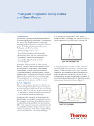
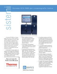
As shown in Figure 1, the <strong>Dionex</strong> <strong>CES</strong> suppressor uses a three chamber design to minimize dead volume while<br />
maximizing suppression capacity and reducing noise. The eluent chamber is comprised of an ion-exchange capillary tubing<br />
embedded in a bed of ion-exchange resin that facilitates the efficient exchange of the eluent counter-ions for regenerant ions.<br />
Cathode Chamber<br />
Cation<br />
Exchange<br />
Membrane<br />
Regen Out<br />
(KOH)<br />
–<br />
Eluent In<br />
(KOH, KCl)<br />
K +<br />
Cation<br />
Exchange<br />
Capillary<br />
Cation Exchange<br />
Resin<br />
H +<br />
Eluent Out<br />
(H 2O, HCl)<br />
H +<br />
Conductivity<br />
Detector<br />
Figure 1<br />
<strong>Dionex</strong> A<strong>CES</strong> <strong>300</strong> Suppressor Operated in the AutoSuppression ® Recycle Mode<br />
There are two electrode chambers that are separated from the eluent chamber by ion-exchange membranes. The deionized<br />
water stream, after passing through the ion-exchange bed in the eluent chamber, passes through the cathode and anode<br />
chambers serially. When current is passed through the electrodes, the regenerant ions are generated in the first electrode<br />
chamber; these ions migrate into the eluent chamber via an electric field, maintaining the ion exchange bed in the eluent<br />
chamber in the regenerated form. After co-ions exchange from the eluent ion exchange capillary, the co-ions are pushed out<br />
of the eluent chamber via the electric field into the second electrode chamber. Finally, these co-ions are neutralized by the<br />
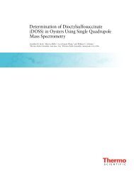
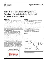
ions generated in the second electrode chamber. The eluent suppression process is illustrated for Anion Suppressor in<br />
Figure 2 and for Cation Suppressor in Figure 3.<br />
Document No. 065386-02 © 2012 <strong>Thermo</strong> Fisher <strong>Scientific</strong> August 2012<br />
+<br />
Anode Chamber
<strong>Product</strong> <strong>Manual</strong> for the <strong>Dionex</strong> <strong>CES</strong> <strong>300</strong> Suppressor Page 5 of 21<br />
Cathode<br />
Analyte in<br />
K + OH -<br />
Cathode<br />
Anode<br />
Analyte in<br />
H + MSA –<br />
Anode<br />
2 H 2O<br />
2 H 2O<br />
2 OH –<br />
+ H 2<br />
Eluent<br />
(KOH)<br />
2 OH –<br />
+ H2<br />
2 H 3O +<br />
+ ½ O2<br />
3 H 2O<br />
Eluent<br />
(MSA)<br />
2 H 3O +<br />
+ ½ O 2<br />
3 H2O<br />
K +<br />
K +<br />
K +<br />
H3O +<br />
OH –<br />
H 3O +<br />
Cation<br />
Exchange Resin<br />
H 2O<br />
Cation<br />
Exchange Resin<br />
Analyte in<br />
H2O<br />
Figure 2<br />
AutoSuppression with the <strong>Dionex</strong> A<strong>CES</strong> <strong>300</strong>.<br />
MSA –<br />
MSA –<br />
MSA –<br />
OH –<br />
H +<br />
OH –<br />
Anion Exchange<br />
Resin<br />
H 2O<br />
Anion Exchange<br />
Resin<br />
Figure 3<br />
AutoSuppresion with the <strong>Dionex</strong> C<strong>CES</strong> <strong>300</strong>.<br />
Analyte in<br />
H 2O<br />
2 H3O +<br />
+ ½ O 2<br />
3 H 2O<br />
2 H 3O +<br />
+ ½ O2<br />
3 H2O<br />
2 OH –<br />
+ H2<br />
2 H2O<br />
2 OH –<br />
+ H 2<br />
2 H 2O<br />
Anode<br />
Detector<br />
Anode<br />
Cathode<br />
Detector<br />
Cathode<br />
<strong>Dionex</strong> <strong>CES</strong> <strong>300</strong> suppressors are designed to operate in an <strong>Thermo</strong> <strong>Scientific</strong> <strong>Dionex</strong> ICS-5000 capillary IC system. The use<br />
of <strong>Dionex</strong> <strong>CES</strong> <strong>300</strong> suppressors in other IC systems is not recommended,<br />
Document No. 065386-02 © 2012 <strong>Thermo</strong> Fisher <strong>Scientific</strong> August 2012
<strong>Product</strong> <strong>Manual</strong> for the <strong>Dionex</strong> <strong>CES</strong> <strong>300</strong> Suppressor Page 6 of 21<br />
1.2. Overview of Suppression Modes<br />
Two basic modes of suppression can be performed with the Capillary Electrolytic Suppressor (<strong>Dionex</strong> <strong>CES</strong> <strong>300</strong>):<br />
• AutoSuppression Recycle Mode<br />
• AutoSuppression External Water Mode<br />
AutoSuppression Recycle Mode: In AutoSuppression, the <strong>Dionex</strong> <strong>CES</strong> <strong>300</strong> uses detector cell effluent to generate the<br />
regenerant for eluent suppression. There are two modes of AutoSuppression operation. The most simple and recommended<br />
mode of operation is the AutoSuppression Recycle Mode. In this mode of operation, eluent flows from the eluent outlet of the<br />
suppressor into the conductivity cell and is then recycled back through the <strong>Dionex</strong> <strong>CES</strong> <strong>300</strong> regenerant chambers. This<br />
eliminates the need for an external source of regenerant water but limits the regenerant flow rate to the eluent flow rate. The<br />
AutoSuppression Recycle Mode is the most common mode of operation and is recommended for aqueous eluents.<br />
AutoSuppression External Water Mode: This mode incorporates an external source of deionized water flowing through<br />
the regenerant chambers. The detector cell effluent is directed to waste. This requires the installation of pressurized bottle<br />
system or additional pump to provide an external source of water. With this configuration the regenerant flow rate is not<br />
limited to the eluent flow rate. The AutoSuppression External Water mode is primarily recommended for eluents containing<br />
solvent (up to 40%), samples that have high solvent or transition metal content, or for interfacing to destructive detectors<br />
such as MS detectors.<br />
1.3. Mode of Operation Selection<br />
The <strong>Dionex</strong> <strong>CES</strong> <strong>300</strong> mode of operation depends mainly on your eluent or sample composition, or your type of<br />
detection. The eluent and sample compatibilities are shown in<br />
Table 1. For example, eluents containing organic solvents are not compatible with the AutoSuppression Recycle Mode. The<br />
AutoSuppression External Water Mode should be used instead.<br />
Eluent / Sample<br />
Composition<br />
Recycle Mode External Water Mode<br />
Aqueous Eluents Yes Yes<br />
Eluent Containing<br />
Organic Solvents<br />
Samples Containing<br />
Organic Solvents<br />
High Transition Metal<br />
Content<br />
No Yes (Up to 40%)<br />
Not Recommended Yes<br />
Not Recommended Yes<br />
Table 1<br />
Eluent and Sample Composition and Suppression Mode Compatibility.<br />
Document No. 065386-02 © 2012 <strong>Thermo</strong> Fisher <strong>Scientific</strong> August 2012
<strong>Product</strong> <strong>Manual</strong> for the <strong>Dionex</strong> <strong>CES</strong> <strong>300</strong> Suppressor Page 7 of 21<br />
1.3.1. AutoSuppression Recycle Mode<br />
The AutoSuppression Recycle Mode uses the neutralized conductivity cell effluent as the source of water for the regenerant<br />
chamber water. This is the preferred method of operation for the <strong>Dionex</strong> <strong>CES</strong> <strong>300</strong>. The advantage of this mode of operation<br />
is simplicity and ease of use. This mode reliably provides AutoSuppression for most suppressed conductivity applications<br />
using solvent-free eluents. As the eluent passes through the <strong>Dionex</strong> <strong>CES</strong> <strong>300</strong>, it is neutralized to its weakly ionized form.<br />
After passing through the conductivity cell, the effluent is redirected to the regenerant inlet on the <strong>Dionex</strong> <strong>CES</strong> <strong>300</strong>, thus<br />
supplying it with a source of water containing minute amounts of diluted analyte. The amount of water flowing through the<br />
regenerant chambers is therefore limited to the eluent flow rate. See Section 3.4 for complete operating instructions.<br />
1.3.2. AutoSuppression External Water Mode<br />
The AutoSuppression External Water Mode is used for any application requiring organic solvents in the eluent or sample, or<br />
when the sample is heavily contaminated with transition metals. This mode uses a constant source of deionized water from a<br />
pressurized bottle or other source of deionized water that delivers 0.01 to 0.05 mL/min. The amount of water flowing through<br />
the regenerant chambers is therefore independent of the eluent flow rate. The AutoSuppression External Water Mode<br />
eliminates the potential for build-up of contaminating ions resulting from the oxidation of solvents. It also prevents re-entry<br />
of transition metals into the regenerant chambers where they may precipitate. Any analysis performed using the<br />
AutoSuppression Recycle Mode can also be performed using the AutoSuppression External Water Mode. See Section 3.5 for<br />
complete operating instructions.<br />
Document No. 065386-02 © 2012 <strong>Thermo</strong> Fisher <strong>Scientific</strong> August 2012
<strong>Product</strong> <strong>Manual</strong> for the <strong>Dionex</strong> <strong>CES</strong> <strong>300</strong> Suppressor Page 8 of 21<br />
SECTION 2 – INSTALLATION<br />
2.1. System Requirements<br />
The <strong>Dionex</strong> <strong>CES</strong> <strong>300</strong> is designed to be run on a <strong>Dionex</strong> Capillary Ion Chromatography System, such as an <strong>Dionex</strong> ICS-5000<br />
equipped with a capillary pump and IC Cube, Anion or Cation exchange column set and conductivity detection. The <strong>Dionex</strong><br />
ICS-<strong>300</strong>0, ICS-2100, ICS-1600, and ICS-1100 and other ion chromatography systems are not equipped to operate with a<br />
<strong>Dionex</strong> <strong>CES</strong> suppressor.<br />
2.2. Back Pressure Coils for the <strong>Dionex</strong> <strong>CES</strong> <strong>300</strong><br />
Back pressure coils are not recommended for the <strong>Dionex</strong> <strong>CES</strong> <strong>300</strong> suppressor when operating with hydroxide or MSA<br />
eluents.<br />
2.3. Gas Separator Waste Tube for the <strong>Dionex</strong> <strong>CES</strong> <strong>300</strong><br />
The Gas Separator Waste Tube (P/N 045460) is an integral part of the <strong>Dionex</strong> IC system using an electrolytic suppressor. It<br />
separates any hydrogen gas generated in the <strong>Dionex</strong> A<strong>CES</strong> <strong>300</strong> during the electrolytic generation of hydronium ions (H3O + )<br />
or hydroxide ions (OH – ) for the <strong>Dionex</strong> C<strong>CES</strong> <strong>300</strong>. The Gas Separator Waste Tube is used to avoid concentrating the gas in<br />
the waste container. The Gas Separator Waste Tube is shipped in one of the ShipKits of your system.<br />
CAUTION<br />
SAFETY<br />
Do not cap the waste reservoir.<br />
Minimal hydrogen gas generated by the <strong>Dionex</strong> <strong>CES</strong> <strong>300</strong> is not dangerous unless the<br />
gas is trapped in a closed container and allowed to concentrate. The Gas Separator<br />
Waste Tube must be open to the atmosphere, and not in a confined space, to operate<br />
properly.<br />
2.3.1. Assembly<br />
Assemble and install the Gas Separator Waste Tube and waste line following the steps below.<br />
A. Use one or two couplers (P/N 045463) to connect two or three lengths of 1/2" i.d. black polyethylene tubing (P/N<br />
045462) depending on the waste container depth. Extend the top of the Waste Separator Tube above the top of the<br />
Waste container.<br />
B. Place the Gas Separator Waste Tube with the 1/8" o.d. tubing attached into the waste container. Ensure the bottom<br />
of the Gas Separator Waste Tube is resting on the floor of the waste container, the top of the device (where the white<br />
1/8" o.d. tubing meets the black 1/2" o.d. tubing) is above the top of the container, and that both the Gas Separator<br />
Waste Tube and the waste container are open to the atmosphere.<br />
2.4. Capillary Electrolytic Suppressor Current Calculation<br />
For optimal performance of the <strong>Dionex</strong> <strong>CES</strong> <strong>300</strong>, <strong>Dionex</strong> recommends the use of the following formulas to calculate the<br />
current applied to the suppressor.<br />
For <strong>Dionex</strong> A<strong>CES</strong> <strong>300</strong>:<br />
SuppressorCurrent (mA) = ((2 * Carbonate concentration (mM) + Bicarbonate concentration (mM) + Hydroxide<br />
concentration (mM)) * FlowRate (µL/min) / 100) + 5 (mA)<br />
For <strong>Dionex</strong> C<strong>CES</strong> <strong>300</strong>:<br />
SuppressorCurrent (mA) = ((2 * H2SO4 concentration (mM) + MSA concentration (mM)) * FlowRate (µL/min) / 100) + 5<br />
(mA)<br />
Multiply by a factor of 1000 to convert the flow rate in mL/min to µL/min. For example, 0.01 mL/min = 10 µL/min.<br />
The suppressor current for <strong>Dionex</strong> <strong>CES</strong> <strong>300</strong> suppressors can also be determined using CM 6.8, 7.0 or later suppressor current<br />
calculation wizard. The maximum current for <strong>Dionex</strong> <strong>CES</strong> <strong>300</strong> suppressor is 25 mA.<br />
Document No. 065386-02 © 2012 <strong>Thermo</strong> Fisher <strong>Scientific</strong> August 2012
<strong>Product</strong> <strong>Manual</strong> for the <strong>Dionex</strong> <strong>CES</strong> <strong>300</strong> Suppressor Page 9 of 21<br />
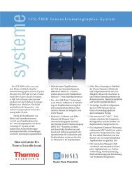
2.5. Installation<br />
To install, remove the caps from the <strong>Dionex</strong> <strong>CES</strong> <strong>300</strong> regenerant ports on the rear of the cartridge and slide the <strong>Dionex</strong> <strong>CES</strong><br />
<strong>300</strong> into the suppressor receptacle of the IC cube installed in a <strong>Dionex</strong> Capillary IC system. Press the <strong>Dionex</strong> <strong>CES</strong> <strong>300</strong> firmly<br />
to establish the electrical and regenerant connections at the rear, and then screw the thumb screws to lock the <strong>Dionex</strong> <strong>CES</strong><br />
<strong>300</strong> in place.<br />
Figure 4<br />
Placement of the <strong>Dionex</strong> <strong>CES</strong> <strong>300</strong> in a <strong>Dionex</strong> ICS-5000 IC Cube (<strong>Dionex</strong> <strong>CES</strong> <strong>300</strong> highlighted in Red) with optional<br />
<strong>Thermo</strong> <strong>Scientific</strong> <strong>Dionex</strong> CRD 200 Carbonate Removal Device.<br />
WARNING<br />
WARNING<br />
WARNING<br />
Do not attempt to plug the <strong>Dionex</strong> <strong>CES</strong> <strong>300</strong> into any receptacle other than the<br />
Suppressor receptacle; damage to the regenerant ports may occur. See the system<br />
manual for details.<br />
<strong>Dionex</strong> <strong>CES</strong> <strong>300</strong> suppressors are designed to operate only with <strong>Dionex</strong> ICS Capillary<br />
IC Systems equipped with IC Cubes.<br />
It is required that the temperature of the upper compartment of the DC be maintained<br />
at 15 °C when using <strong>Dionex</strong> <strong>CES</strong> <strong>300</strong> suppressors in a <strong>Dionex</strong> ICS Capillary IC<br />
system.<br />
Document No. 065386-02 © 2012 <strong>Thermo</strong> Fisher <strong>Scientific</strong> August 2012
<strong>Product</strong> <strong>Manual</strong> for the <strong>Dionex</strong> <strong>CES</strong> <strong>300</strong> Suppressor Page 10 of 21<br />
SECTION 3 – OPERATION<br />
This section provides instructions for the start-up and operation of the <strong>Dionex</strong> <strong>CES</strong> <strong>300</strong> including the selection process and<br />
suppression modes of operation.<br />
3.1. Chemical Purity Requirements<br />
Precise and accurate results require eluents free of ionic impurities. Chemicals and deionized water used to prepare eluents<br />
must be pure as described below. Low trace impurities and low particulate levels in eluents and regenerants also help protect<br />
the <strong>Dionex</strong> <strong>CES</strong> <strong>300</strong> and system components from contamination. <strong>Dionex</strong> <strong>CES</strong> <strong>300</strong> performance is not guaranteed when the<br />
quality of the chemicals and water used to prepare eluents has been compromised.<br />
3.2. Inorganic Chemicals<br />
Reagent Grade inorganic chemicals should always be used to prepare ionic eluents. Preferably, a lot analysis on each label<br />
will certify each chemical as meeting or surpassing the latest American Chemical Society standard for purity, a universally<br />
accepted standard for reagents.<br />
3.2.1. Solvents<br />
Since solvents used with the <strong>Dionex</strong> <strong>CES</strong> <strong>300</strong> are added to ionic eluents to modify the ion exchange process or improve<br />
sample solubility, the solvents used must be free of ionic impurities. However, since most solvent manufacturers do not test<br />
for ionic impurities, the highest grade of solvents available should be used. Currently, several manufacturers are making<br />
ultra-high purity solvents that are compatible for HPLC and spectrophotometric applications. These ultra-high purity<br />
solvents will usually ensure that your chromatography is not affected by ionic impurities in the solvent. <strong>Dionex</strong> has obtained<br />
consistent results using High Purity Solvents manufactured by Burdick and Jackson and Optima ® Solvents by Fisher<br />
<strong>Scientific</strong>.<br />
3.2.2. Deionized Water<br />
The deionized water used to prepare eluents should be degassed Type I Reagent Grade Water with a specific resistance of<br />
18.2 megohm-cm. The water used for the AutoSuppression External Water Mode should have a specific resistance of 18.2<br />
megohm-cm or greater. The deionized water should be free of ionized impurities, organics, microorganisms and particulate<br />
matter larger than 0.2 µm. It is good practice to filter eluents through a 0.2 µm filter whenever possible. Bottled HPLC-<br />
Grade Water should not be used since most bottled water contains an unacceptable level of ionic impurities. Finally,<br />
thoroughly degas all deionized water prior to preparing any eluents or regenerants.<br />
3.3. Start-up<br />
The <strong>Dionex</strong> <strong>CES</strong> <strong>300</strong> is plumbed directly after the analytical column and before the carbonate removal device (if fitted) and<br />
conductivity detector cell. On the <strong>Dionex</strong> ICS-5000, the suppressor is plugged into the suppressor receptacle of the IC Cube<br />
in the DC; electrical contact and regenerant connections are established upon installation. To install, remove the caps from<br />
the <strong>Dionex</strong> <strong>CES</strong> <strong>300</strong> regenerant ports on the rear of the cartridge and slide the <strong>Dionex</strong> <strong>CES</strong> <strong>300</strong> into the receptacle. Press the<br />
<strong>Dionex</strong> <strong>CES</strong> <strong>300</strong> firmly to establish the regenerant connections, and then screw the thumb screws to lock the <strong>Dionex</strong> <strong>CES</strong><br />
<strong>300</strong> in place. Loosen the thumb screws and pull the cartridge out to remove <strong>Dionex</strong> <strong>CES</strong> <strong>300</strong>. Ensure the <strong>Dionex</strong> <strong>CES</strong> <strong>300</strong> is<br />
plumbed properly according to the selected mode of operation.<br />
WARNING<br />
CAUTION<br />
CAUTION<br />
Keep the regenerant chambers full with the appropriate regenerant solution or water.<br />
The membranes and screens in the <strong>Dionex</strong> <strong>CES</strong> <strong>300</strong> must be completely hydrated to<br />
maintain liquid seals and chromatographic performance.<br />
The correct amount of back pressure for optimum operation is 40 psi. Back pressures<br />
over 150 psi after the <strong>Dionex</strong> <strong>CES</strong> <strong>300</strong> can cause irreversible damage.<br />
Do not cap the waste reservoir.<br />
Document No. 065386-02 © 2012 <strong>Thermo</strong> Fisher <strong>Scientific</strong> August 2012
<strong>Product</strong> <strong>Manual</strong> for the <strong>Dionex</strong> <strong>CES</strong> <strong>300</strong> Suppressor Page 11 of 21<br />
CAUTION<br />
SAFETY<br />
To ensure proper operation of the <strong>Dionex</strong> <strong>CES</strong> suppressor, the temperature of the<br />
upper compartment of the DC module (where the IC Cube resides) must be set to 15<br />
°C.<br />
Hydrogen gas generated by the <strong>Dionex</strong> <strong>CES</strong> <strong>300</strong> is not dangerous unless the gas is<br />
trapped in a closed container and allowed to concentrate. The Gas Separator Waste<br />
Tube must be open to the atmosphere, and not in a confined space, to operate properly.<br />
3.3.1. Hydration<br />
Hydrating the Suppressor Regen Chamber<br />
A. Install the <strong>Dionex</strong> <strong>CES</strong> <strong>300</strong> Suppressor in the IC Cube.<br />
B. Install the <strong>Dionex</strong> CRD 200 or the <strong>Dionex</strong> CRD bypass cartridge in the IC Cube.<br />
C. Connect a piece of 24 inch x 1/10 inch x 0.0025 inch blue PEEK tubing (P/N 072203) to the outlet of the <strong>Dionex</strong><br />
ICS-5000 Capillary Pump Pulse Damper.<br />
D. Connect this tubing to the union on the end of the tubing exiting the REGEN IN port of the capillary suppressor<br />
cartridge (Figure 3). (This is a temporary connection.)<br />
Eluent In<br />
CRD 200<br />
400-um<br />
Eluent Out<br />
Eluent In<br />
Eluent Out<br />
Regen In<br />
Eluent Out<br />
Eluent In<br />
SAMPLE IN<br />
SAMPLE OUT<br />
To Suppressor<br />
Regen In<br />
(orange label)<br />
Cell In<br />
ELUENT OUT<br />
ELUENT IN<br />
Suppressor and CRD Hydration:<br />
Pump at 0.05 mL/min for 15 min<br />
Cell Out<br />
Document No. 065386-02 © 2012 <strong>Thermo</strong> Fisher <strong>Scientific</strong> August 2012<br />
Regen Out<br />
Eluent Out<br />
EG<br />
DEGAS<br />
Eluent In<br />
Pre-plumbed to<br />
suppressor Regen In<br />
Union<br />
To EG Degas<br />
Regen Out<br />
(blue label)<br />
0.25-mm (0.010-in) ID<br />
PEEK tubing<br />
(Temporary connection)<br />
To Waste<br />
From Pump Outlet<br />
0.25-mm (0.010-in) ID<br />
PEEK tubing<br />
(Temporary connection)<br />
Figure 5<br />
Flow Schematic for Hydrating the Capillary Suppressor and <strong>Dionex</strong> CRD<br />
E. Connect a piece of 0.25 mm (0.010 in) ID PEEK tubing to the REGEN OUT port of the capillary EG degas cartridge<br />
in the IC Cube. Direct the other end of the tubing to waste. (This is a temporary connection.)<br />
F. Set the pump flow rate to 0.05 mL/min and turn on the pump flow.<br />
G. Run the pump for 15 minutes and then turn off the pump flow. This hydrates the capillary suppressor and flushes the<br />
internal IC Cube regenerant manifold chambers.
<strong>Product</strong> <strong>Manual</strong> for the <strong>Dionex</strong> <strong>CES</strong> <strong>300</strong> Suppressor Page 12 of 21<br />
Hydrating the Suppressor Eluent Chamber<br />
A. Install the <strong>Dionex</strong> <strong>CES</strong> <strong>300</strong> Suppressor in the IC Cube.<br />
B. Install the <strong>Dionex</strong> CRD 200 or the <strong>Dionex</strong> CRD bypass cartridge in the IC Cube.<br />
C. Connect a piece of 24 inch x 1/10 inch x 0.0025 inch blue PEEK tubing (P/N 072203) to the outlet of the <strong>Dionex</strong><br />
ICS-5000 Capillary Pump Pulse Damper.<br />
D. Connect this tubing through a 10-32 union to the inlet end of the <strong>Dionex</strong> <strong>CES</strong> <strong>300</strong> suppressor.<br />
E. Set the pump flow rate to 0.01 mL/min and turn on the pump flow.<br />
F. Run the pump for 10 minutes and then turn off the pump flow. This hydrates the capillary suppressor.<br />
3.4. Plumbing for the AutoSuppression Recycle Mode of Operation<br />
The AutoSuppression Recycle Mode is the easiest method of operation. As the eluent passes through the suppressor, it is<br />
neutralized to produce its weakly ionized form. After passing through the conductivity cell, this effluent can be redirected to<br />
the regenerant inlet of the suppressor, thus supplying it with a source of water containing a small amount of diluted analyte<br />
(see Figure 6). The main advantage of this mode is its simplicity and ease of use. It is not necessary to have an external<br />
supply of water<br />
available for the suppressor.<br />
CAUTION<br />
CAUTION<br />
Figure 6<br />
Schematic of <strong>Dionex</strong> ICS-5000 IC Cube in AutoSuppression Recycled Eluent Mode.<br />
Connections 12 and 13 route cell effluent to the <strong>Dionex</strong> <strong>CES</strong> <strong>300</strong> Regen In.<br />
To ensure proper operation of the <strong>Dionex</strong> <strong>CES</strong> suppressor, the temperature of the<br />
upper compartment of the DC module (where the IC Cube resides) must be set to 15<br />
°C.<br />
Only use the AutoSuppression Recycle Mode for eluents without organic solvents and<br />
samples without excessive metallic contaminants such as iron.<br />
Document No. 065386-02 © 2012 <strong>Thermo</strong> Fisher <strong>Scientific</strong> August 2012
<strong>Product</strong> <strong>Manual</strong> for the <strong>Dionex</strong> <strong>CES</strong> <strong>300</strong> Suppressor Page 13 of 21<br />
3.4.1. Eluent Flow Path Connections in the AutoSuppression Recycle Mode<br />
Use only the provided pre-cut 0.0025" i.d. PEEK tubing (light blue) with 10-32 ferrule/bolt fittings. When connecting<br />
the fittings, make sure that the ferrule and fitting bolt are at least 2 mm (0.1 in) from the end of the tubing before you<br />
insert the tubing into the port. Do not place the ferrule and fitting bolt flush with the end of the tubing.<br />
Figure 7 illustrates the correct and incorrect placement of the ferrule and fitting bolt on the tubing.<br />
NOTE<br />
Figure 7<br />
Correct and Incorrect Ferrule and Fitting Placement for Capillary Tubing Connections<br />
Always use the precut tubing included with the suppressor and other capillary devices<br />
to make connections. Do not cut or alter this tubing; the tubing is factory cut for an<br />
extremely low dead volume interface.<br />
A. Install the <strong>Dionex</strong> <strong>CES</strong> <strong>300</strong> in the Suppressor cartridge receptacle.<br />
B. Connect the outlet of the capillary column to the ELUENT IN of the <strong>Dionex</strong> <strong>CES</strong> <strong>300</strong> (Connection 7 in Figure 6).<br />
C. Connect the ELUENT OUT port of the <strong>Dionex</strong> <strong>CES</strong> <strong>300</strong> to the inlet of the <strong>Dionex</strong> CRD 200 (Connection 9 in<br />
Figure 6) if a <strong>Dionex</strong> CRD 200 is installed, or to the inlet of the conductivity cell (Connection 11 in Figure 6) if no<br />
<strong>Dionex</strong> CRD 200 is installed.<br />
D. Connect the REGEN IN port of the <strong>Dionex</strong> <strong>CES</strong> <strong>300</strong> to the outlet of the conductivity cell (Connection 12 in Figure<br />
6) using the black (0.010”) REGEN IN tubing.<br />
Document No. 065386-02 © 2012 <strong>Thermo</strong> Fisher <strong>Scientific</strong> August 2012
<strong>Product</strong> <strong>Manual</strong> for the <strong>Dionex</strong> <strong>CES</strong> <strong>300</strong> Suppressor Page 14 of 21<br />
3.5. Plumbing for the AutoSuppression External Water Mode Operation<br />
Any analysis that can be performed using the AutoSuppression Recycle Mode can be done using the AutoSuppression<br />
External Water Mode. A constant source of deionized water having a specific resistance of 18.2 megohm, or greater, is<br />
supplied to the regenerant chambers to generate hydronium or hydroxide ions for neutralization.<br />
CAUTION<br />
AutoSuppression External Water Mode is recommended for eluents with organic<br />
solvents, samples with high levels of metallic contaminants such as iron, or destructive<br />
detection methods where a source of suppressed eluent is not available.<br />
3.5.1. Eluent Flow Path Connections for the AutoSuppression External Water Mode<br />
Use only the provided pre-cut 0.0025" i.d. PEEK tubing (light blue) with 10-32 ferrule/bolt fittings. When connecting<br />
the fittings, make sure that the ferrule and fitting bolt are at least 2 mm (0.1 in) from the end of the tubing before you<br />
insert the tubing into the port. Do not place the ferrule and fitting bolt flush with the end of the tubing.<br />
Figure 7 illustrates the correct and incorrect placement of the ferrule and fitting bolt on the tubing.<br />
NOTE<br />
Always use the precut tubing included with the suppressor and other capillary devices<br />
to make connections. Do not cut or alter this tubing; the tubing is factory cut for an<br />
extremely low dead volume interface.<br />
A. Install the <strong>Dionex</strong> <strong>CES</strong> <strong>300</strong> in the Suppressor cartridge receptacle.<br />
B. Connect the outlet of the analytical column to the ELUENT IN of the <strong>Dionex</strong> <strong>CES</strong> <strong>300</strong> (Connection 7 in Figure 6).<br />
C. Connect the ELUENT OUT port of the <strong>Dionex</strong> <strong>CES</strong> <strong>300</strong> to the inlet of the <strong>Dionex</strong> CRD 200 (Connection 9 in<br />
Figure 6) if a <strong>Dionex</strong> CRD 200 is installed, or to the inlet of the conductivity cell (Connection 11 in Figure 6) if no<br />
<strong>Dionex</strong> CRD 200 is installed.<br />
D. If using conductivity detection only, install a waste line to the conductivity cell outlet. If using a hyphenated<br />
technique such as CD-MSD, connect the inlet of the second detector to the outlet of the conductivity cell using<br />
tubing of the appropriate length and i.d. depending on your application requirements. If using a detection technique<br />
other than conductivity, connect the outlet of the <strong>Dionex</strong> <strong>CES</strong> <strong>300</strong> to the inlet of the detector using tubing of the<br />
appropriate length and i.d. depending on your application requirements.<br />
E. Connect the REGEN IN port of the <strong>Dionex</strong> <strong>CES</strong> <strong>300</strong> to the source of external water.<br />
F. Adjust the flow rate of water from the external water delivery system to the REGEN IN of the <strong>Dionex</strong> <strong>CES</strong> <strong>300</strong> to<br />
approximately 0.050 mL/min.<br />
NOTE<br />
To ensure the optimal performance of the <strong>Dionex</strong> <strong>CES</strong> <strong>300</strong> in the AutoSuppressor<br />
External Water Mode, it is recommended to use a pump that is capable of delivering<br />
deionized water accurately and reproducibly at 0.050 mL/min.<br />
Document No. 065386-02 © 2012 <strong>Thermo</strong> Fisher <strong>Scientific</strong> August 2012
<strong>Product</strong> <strong>Manual</strong> for the <strong>Dionex</strong> <strong>CES</strong> <strong>300</strong> Suppressor Page 15 of 21<br />
3.5.2. Using a Pressurized Bottle to provide External Water<br />
The SRS <strong>300</strong> Pressurized Bottle Installation Kit (P/N 038018) contains all of the components needed to install and operate<br />
the <strong>Dionex</strong> <strong>CES</strong> <strong>300</strong> with a pressurized water reservoir. The kit contains the Installation Parts Kit (P/N 039055), a 25 psi<br />
regulator (P/N 038201) and a 4 liter water reservoir (P/N 039164).<br />
A. Make the following air line connections:<br />
a. Locate the pieces of tinted 1/8" o.d. plastic tubing (P/N 0<strong>300</strong>89) supplied in the Installation Parts Kit.<br />
b. Push the end of one piece of 1/8" o.d. tubing over the barbed fitting of the regulator. Connect the other end<br />
of the tubing to the source of air pressure.<br />
c. Push one end of the second piece of 1/8" o.d. tubing over the other barbed fitting of the regulator. Push the<br />
other end of this tubing over the barbed fitting (P/N 0<strong>300</strong>77) in the pressure inlet of the plastic reservoir.<br />
B. Make the following water line connection.<br />
a. Use a 10-32 to ¼-28 coupler (P/N 42806) to connect one end of the 30" tubing assembly (P/N 035727) that<br />
comes in the Installation Kit to the water reservoir. Connect the other end of this tubing to the REGEN IN<br />
tubing of the <strong>Dionex</strong> <strong>CES</strong> <strong>300</strong>.<br />
C. Fill the water source reservoir. Make sure that the O-ring is inside the cap of the reservoir before screwing the cap<br />
onto the reservoir. Screw the cap onto the reservoir tightly and place the reservoir near the Chromatography Module.<br />
D. With no current applied, adjust the external water flow rate to approximately 0.050 to 0.10 mL/min by using a<br />
graduated cylinder and measuring the flow from the REGEN OUT line of the EG Degas cartridge (Connection 14 in<br />
Figure 6). The pressure applied to the reservoir can vary from 0–25 psi (the lower and upper pressure limits of the<br />
water reservoir) but the typical operating pressure is between 10–15 psi. Please note that this value is highly system<br />
dependent. After turning on the current, the external water flow rate will be less because the electrolysis of water<br />
will generate a small amount of hydrogen and oxygen gases that will be seen as bubbles from the REGEN OUT<br />
waste line. The flow rate with current turned on should be at least equal to the eluent flow rate.<br />
SAFETY<br />
A safety relief valve on the reservoir regulator prevents pressure greater than 25 psi<br />
from being applied to the water reservoir.<br />
3.5.3. Using a External Pump to provide External Water<br />
To ensure the optimal performance of <strong>Dionex</strong> <strong>CES</strong> <strong>300</strong> in the AutoSuppression External Water Mode, it is recommended to<br />
use a pump such as the <strong>Dionex</strong> DP pump that is capable of delivering deionized water at 0.05 mL/min accurately and<br />
consistently.<br />
For peristaltic pump plumbing refer to the “MASTERFLEX ® C/L ® Peristaltic Pump Quick Start Guide” (P/N 065203). Pump<br />
the Deionized water into the REGEN IN port of the <strong>Dionex</strong> <strong>CES</strong> <strong>300</strong> using the peristaltic pump at 0.050 mL/min. Use a<br />
graduated cylinder and measure the flow from the REGEN OUT line of the EG Degas cartridge (Connection 14 in Figure 6).<br />
Document No. 065386-02 © 2012 <strong>Thermo</strong> Fisher <strong>Scientific</strong> August 2012
<strong>Product</strong> <strong>Manual</strong> for the <strong>Dionex</strong> <strong>CES</strong> <strong>300</strong> Suppressor Page 16 of 21<br />
3.6. Capillary Electrolytic Suppressor <strong>300</strong> (<strong>Dionex</strong> <strong>CES</strong> <strong>300</strong>) Storage<br />
The <strong>Dionex</strong> <strong>CES</strong> <strong>300</strong> is shipped with DI water as the storage solution. If the suppressor will not be used for more than one<br />
week, prepare it for storage. The membranes and resin in the <strong>Dionex</strong> <strong>CES</strong> <strong>300</strong> must be completely hydrated to maintain<br />
liquid seal and chromatographic performance. Plug all the ports after hydration.<br />
3.6.1. Storage<br />
A. Remove the <strong>Dionex</strong> <strong>CES</strong> <strong>300</strong> from the IC Cube.<br />
B. Flush the <strong>Dionex</strong> <strong>CES</strong> <strong>300</strong> eluent port with deionized water for 10 minutes using the eluent delivery pump set to<br />
0.010 mL/min with the eluent generator, CR-TC, separation column bypassed.<br />
C. Use the eluent delivery pump to pump deionized water through the REGEN IN port for 10 minutes at 0.05 mL/min.<br />
D. Use a 10-32 coupler to connect the suppressor ELUENT INLET and OUTLET.<br />
E. Plug the REGEN OUT port using the nylon plastic cap provided with the <strong>Dionex</strong> <strong>CES</strong> suppressor.<br />
Document No. 065386-02 © 2012 <strong>Thermo</strong> Fisher <strong>Scientific</strong> August 2012
<strong>Product</strong> <strong>Manual</strong> for the <strong>Dionex</strong> <strong>CES</strong> <strong>300</strong> Suppressor Page 17 of 21<br />
SECTION 4 – TROUBLESHOOTING GUIDE<br />
The purpose of the Troubleshooting Guide is to help you solve operating problems that may arise while using the <strong>Dionex</strong><br />
<strong>CES</strong> <strong>300</strong>. For more information on problems that originate with the Ion Chromatograph System or the specific exchange<br />
column set in use, refer to the Troubleshooting Guide in the appropriate <strong>Product</strong> <strong>Manual</strong>. If you cannot solve the problem on<br />
your own, contact the <strong>Dionex</strong> Regional Office nearest you (see <strong>Dionex</strong> Worldwide Offices on the Reference Library CD-<br />
ROM).<br />
4.1. Over-voltage Alarm<br />
Higher resistance in the suppressor device typically causes an over-voltage alarm. High resistance occurs when:<br />
A. The suppressor is operated with higher currents than the recommended currents. The suppressor should only be<br />
operated at the current recommended for the eluent concentration and flow rate.<br />
B. The suppressor is exposed to contaminants such as iron, other metals or organics. Refer to the appropriate cleanup<br />
procedure and implement the recommended cleanup. In cases when the contamination is continuous, a routine<br />
cleanup step on a weekly basis is recommended as part of preventive maintenance.<br />
4.2. Small or Increasing Analyte Peak Areas<br />
This problem is caused by running eluent through the <strong>Dionex</strong> <strong>CES</strong> <strong>300</strong> with the.<br />
A. Disconnect the line from the analytical column attached to the ELUENT IN port of the <strong>Dionex</strong> <strong>CES</strong> <strong>300</strong>.<br />
B. Disconnect the line from the ELUENT OUT port of the <strong>Dionex</strong> <strong>CES</strong> <strong>300</strong>.<br />
C. For the <strong>Dionex</strong> A<strong>CES</strong> <strong>300</strong>:<br />
a.<br />
b.<br />
Fill a 1 mL plastic syringe with 0.5 mL of 200 mN H2SO4 .<br />
Connect the OUTLET of the syringe to the ELUENT INLET of the <strong>Dionex</strong> A<strong>CES</strong> suppressor.<br />
c. Push approximately 0.3 mL of 200 mN H2SO4 slowly through the ELUENT IN port of the <strong>Dionex</strong> A<strong>CES</strong><br />
suppressor.<br />
d. Use a piece of pH paper to collect a small drop of the effluent coming out of the <strong>Dionex</strong> A<strong>CES</strong> suppressor<br />
OUTLET.<br />
e. Make sure that the pH paper indicates the effluent is less than pH 1.<br />
f. Connect a piece of 24 inch x 1/10 inch x 0.0025 inch blue PEEK tubing (P/N 072203) to the OUTLET of<br />
the <strong>Dionex</strong> ICS-5000 capillary pump pulse damper.<br />
g. Connect this tubing through a 10-32 union to the INLET end of the <strong>Dionex</strong> <strong>CES</strong> <strong>300</strong> suppressor.<br />
h. Set the pump flow rate to 0.01 mL/min and turn on the pump flow.<br />
i. Run the pump for 10 minutes and then turn off the pump flow.<br />
D. For the <strong>Dionex</strong> C<strong>CES</strong> <strong>300</strong><br />
a. Fill a 1 mL plastic syringe with 0.5 mL of 200 mN NaOH.<br />
b. Connect the OUTLET of the syringe to the ELUENT INLET of the <strong>Dionex</strong> A<strong>CES</strong> suppressor.<br />
c. Push approximately 0.3 mL of 200 mN NaOH slowly through the ELUENT IN port of the <strong>Dionex</strong> A<strong>CES</strong><br />
suppressor.<br />
d. Use a piece of pH paper to collect a small drop of the effluent coming out of the <strong>Dionex</strong> A<strong>CES</strong> suppressor<br />
OUTLET.<br />
e. Make sure that the pH paper indicates the effluent is less than pH 3.<br />
f. Connect a piece of 24 inch x 1/10 inch x 0.0025 inch blue PEEK tubing (P/N 072203) to the OUTLET of<br />
the <strong>Dionex</strong> ICS-5000 capillary pump pulse damper.<br />
g. Connect this tubing through a 10-32 union to the INLET end of the <strong>Dionex</strong> <strong>CES</strong> <strong>300</strong> suppressor.<br />
h. Set the pump flow rate to 0.01 mL/min and turn on the pump flow.<br />
i. Run the pump for 10 minutes and then turn off the pump flow.<br />
E. Reconnect the line from analytical column to the ELUENT IN port of the <strong>Dionex</strong> <strong>CES</strong> <strong>300</strong> and the line from the<br />
ELUENT OUT port of the <strong>Dionex</strong> <strong>CES</strong> <strong>300</strong> to the ELUENT IN port of the conductivity detector cell.<br />
F. If you are in the Auto Suppression Recycle mode of operation, begin pumping eluent and immediately turn on the<br />
power.<br />
Document No. 065386-02 © 2012 <strong>Thermo</strong> Fisher <strong>Scientific</strong> August 2012
<strong>Product</strong> <strong>Manual</strong> for the <strong>Dionex</strong> <strong>CES</strong> <strong>300</strong> Suppressor Page 18 of 21<br />
G. If you are in the Auto Suppression External water mode of operation, establish water flow through the regenerant<br />
chambers, begin pumping eluent and immediately turn on the power.<br />
NOTE<br />
NOTE<br />
NOTE<br />
Do not let the eluent flow through the <strong>Dionex</strong> <strong>CES</strong> <strong>300</strong> for more than a few minutes<br />
without turning on the power.<br />
The sulfuric acid in the above steps could be replaced with a non oxidizing strong<br />
acid such as Methanesulfonic acid (MSA) which is recommended when pursuing MS<br />
applications.<br />
Do not use the Analytical pump for regeneration purpose as this will contaminate the<br />
pump.<br />
4.3. High Background Conductivity<br />
A. Check for eluent flow out of the <strong>Dionex</strong> <strong>CES</strong> <strong>300</strong> ELUENT OUT port.<br />
a. If there is no flow out of the <strong>Dionex</strong> <strong>CES</strong> <strong>300</strong> ELUENT OUT port, make sure that eluent is entering the<br />
<strong>Dionex</strong> <strong>CES</strong> <strong>300</strong> at the ELUENT IN port. If there is no flow at this point, trace the eluent flow path<br />
backward through the system to find and remove the blockage.<br />
b. If there is flow into the <strong>Dionex</strong> <strong>CES</strong> <strong>300</strong> but not out, and there are no visible leaks from the suppressor, a<br />
break in the eluent capillary is probably allowing eluent to leak into the regenerant chambers. If this is the<br />
case, then the <strong>Dionex</strong> <strong>CES</strong> <strong>300</strong> must be replaced. The <strong>Dionex</strong> <strong>CES</strong> <strong>300</strong> is sealed during manufacture;<br />
attempting to open it will destroy it.<br />
c. If there is flow from the ELUENT OUT port, but no eluent suppression, the membrane may have been<br />
contaminated. Try to restore system performance by cleaning the membrane.<br />
B. Check the eluent concentration to be sure that it is correct. Be sure that water of the required purity is being used as<br />
eluent (see Section 3.1, “Chemical Purity Requirements”). If the eluent concentration is high, the <strong>Dionex</strong> <strong>CES</strong> <strong>300</strong><br />
may not be set up to suppress the high concentration resulting in high background conductivity. Use CM 6.8, 7.0 or<br />
later suppressor current calculator wizard to calculate the correct suppression current setting for <strong>Dionex</strong> <strong>CES</strong> <strong>300</strong><br />
suppression.<br />
C. Contact the nearest <strong>Dionex</strong> Regional Office (see, “<strong>Dionex</strong> Worldwide Offices”) if you cannot solve the problem on<br />
your own.<br />
NOTE<br />
Do not exceed 25 mA with the <strong>Dionex</strong> <strong>CES</strong> <strong>300</strong> suppressor.<br />
4.4. Drifting baseline<br />
If the baseline drifts steadily upward, increase the current setting up to 25 mA if necessary to reduce the background<br />
conductivity. As the background conductivity decreases, the baseline drift should decrease.<br />
NOTE<br />
Do not exceed 25 mA with the <strong>Dionex</strong> <strong>CES</strong> <strong>300</strong> suppressor.<br />
4.5. Noisy baseline<br />
If the baseline is noisy (> 5 nS), it could be caused by trapped air bubbles in the cell or tubing. Burp or release the trapped<br />
bubbles by gently tapping on the cell while the fittings are slightly loosened or bleeding the tubing.<br />
Document No. 065386-02 © 2012 <strong>Thermo</strong> Fisher <strong>Scientific</strong> August 2012
<strong>Product</strong> <strong>Manual</strong> for the <strong>Dionex</strong> <strong>CES</strong> <strong>300</strong> Suppressor Page 19 of 21<br />
4.6. Decreased sensitivity<br />
A. Check for leaks throughout the system. If a fitting is leaking, tighten it carefully until the leak stops. Do not over<br />
tighten. If the <strong>Dionex</strong> <strong>CES</strong> <strong>300</strong> is observed to be leaking, see Section 4.8, “Liquid Leaks.” If you cannot cure the<br />
problem yourself, call the nearest <strong>Dionex</strong> Regional Office (see, “<strong>Dionex</strong> Regional Offices”) for assistance.<br />
B. Ensure that the injection valve is operating correctly. Refer to the valve manuals that accompany the<br />
chromatography module for troubleshooting assistance.<br />
C. Pursue regeneration of the suppressor as outlined in section 4.2.<br />
D. If sensitivity remains low, clean the suppressor membrane (see Section 5, “Suppressor Cleanup”).<br />
E. Check the backpressure on the cell. Verify it is not exceeding 40 psi in the current plumbing configuration and flow<br />
rate.<br />
F. Replace the <strong>Dionex</strong> <strong>CES</strong> <strong>300</strong> if cleaning the suppressor membrane does not restore sensitivity.<br />
G. Contact the nearest <strong>Dionex</strong> Regional Office (see, “<strong>Dionex</strong> Worldwide Offices”) if you cannot solve the problem on<br />
your own.<br />
4.7. System Back Pressure Increases Over Time<br />
A. If the increased back pressure does not affect system performance, no maintenance is necessary.<br />
B. Check the conductivity cell backpressure. If disconnecting the cell lowers the pressure by more than 40 psi, replace<br />
the cell or remove the blockage causing the increased pressure. Backpressure over 150 psi after the suppressor can<br />
cause irreversible damage.<br />
C. Find and eliminate any system blockage. Bypass the <strong>Dionex</strong> <strong>CES</strong> <strong>300</strong> by coupling the lines attached to the ELUENT<br />
IN and ELUENT OUT ports. If the back pressure decreases by less than 150 psi with the <strong>Dionex</strong> <strong>CES</strong> <strong>300</strong> out of<br />
line, a blockage in the system rather than in the <strong>Dionex</strong> <strong>CES</strong> <strong>300</strong> is causing the high pressure.<br />
D. Remove a blockage from <strong>Dionex</strong> <strong>CES</strong> <strong>300</strong> by reversing the eluent flow. If the back pressure decreases by more than<br />
150 psi with the <strong>Dionex</strong> <strong>CES</strong> <strong>300</strong> out of line, the high pressure may be caused by a blockage in the <strong>Dionex</strong> <strong>CES</strong><br />
<strong>300</strong>. Reverse the direction of flow of the eluent or both the eluent and the external water through the <strong>Dionex</strong> <strong>CES</strong><br />
<strong>300</strong>. After the pressure drops, allow eluent, or eluent and regenerant, to flow to waste for several minutes after the<br />
pressure drops. Perform step A of Section 3.2, “Startup” and reinstall the <strong>Dionex</strong> <strong>CES</strong> <strong>300</strong> in the appropriate<br />
configuration.<br />
E. Clean the suppressor membranes if reversing the flow through the <strong>Dionex</strong> <strong>CES</strong> <strong>300</strong> does not decrease the pressure.<br />
(See Section 5, “Suppressor Cleanup”).<br />
F. Replace the <strong>Dionex</strong> <strong>CES</strong> <strong>300</strong> if cleaning the suppressor membrane does not reduce the pressure.<br />
G. Contact the nearest <strong>Dionex</strong> Regional Office (see, “<strong>Dionex</strong> Regional Offices”) if you cannot solve the problem on<br />
your own.<br />
NOTE<br />
Always use the precut tubing included with the suppressor and other capillary devices<br />
to make connections. Do not cut or alter this tubing, or add other tubing other than<br />
<strong>Dionex</strong> pre-cut tubing; the tubing is factory cut for an extremely low dead volume<br />
interface.<br />
Document No. 065386-02 © 2012 <strong>Thermo</strong> Fisher <strong>Scientific</strong> August 2012
<strong>Product</strong> <strong>Manual</strong> for the <strong>Dionex</strong> <strong>CES</strong> <strong>300</strong> Suppressor Page 20 of 21<br />
4.8. Liquid Leaks<br />
If there is leakage from the <strong>Dionex</strong> <strong>CES</strong> <strong>300</strong>, check the back pressure after the suppressor.<br />
If the system back pressure after the suppressor is greater than 150 psi, the leaks are caused by excessive back pressure<br />
downstream from the <strong>Dionex</strong> <strong>CES</strong> <strong>300</strong>. Find and eliminate the source of the pressure. If the <strong>Dionex</strong> <strong>CES</strong> <strong>300</strong> continues to<br />
leak when operated within the proper back pressure range, it must be replaced. The <strong>Dionex</strong> <strong>CES</strong> <strong>300</strong> will not usually recover<br />
from overpressure conditions, so ensure the source of backpressure is eliminated before installing a replacement <strong>Dionex</strong> <strong>CES</strong><br />
<strong>300</strong>.<br />
CAUTION<br />
The correct amount of back pressure for optimum operation is 40 psi. Back pressures<br />
over 150 psi after the <strong>Dionex</strong> <strong>CES</strong> <strong>300</strong> can cause irreversible damage.<br />
4.9. Poor or unstable recovery of certain peaks<br />
If one or two peaks are experiencing poor or unstable recoveries while the other peaks are stable, it could be that the current<br />
to the suppressor is set too high. It is recommended to use the recommended current (see Section 2.4) unless necessary to<br />
stabilize a drifting baseline.<br />
4.10. Peaks and spikes in the absence of an injection<br />
A. Precipitation on the suppressor membrane or screens (calcium, magnesium and other metals): Follow the Metal<br />
Contaminants or Precipitates procedure from section 5.1. To prevent contaminants from reaching the suppressor, a<br />
CP1 cation polisher column (P/N 064930) can be used during anion analysis to strip cationic contaminants from the<br />
sample. Refer to the CP1 Operator’s <strong>Manual</strong> for detailed instructions.<br />
B. Outgassing or trapped bubbles in the suppressor regenerant chambers: Ensure that the external water (if used) is<br />
degassed before use; do not pressurize the external water with air, use nitrogen or helium. Eliminate causes of<br />
excessive backpressure between the cell outlet and the regenerant inlet if recycled eluent mode is used.<br />
C. Excess suppressor temperature: It is important to ensure that the <strong>Dionex</strong> <strong>CES</strong> <strong>300</strong> is operated in an environment of<br />
15°C. Operating the <strong>Dionex</strong> <strong>CES</strong> <strong>300</strong> at a higher temperature may compromise its performance.<br />
D. Large changes to the flow rate or applied current of the suppressor. If the current is changed, allow the suppressor a<br />
few hours to reestablish baseline stability.<br />
E. Operating the suppressor with power but no eluent or regenerant flow: Operation of the suppressor without flow<br />
may irreversibly damage the suppressor, depending on amount of applied current and duration. Ensure that the<br />
regenerant lines are connected and flow is established when powering on the suppressor at all times. Ensure that<br />
during external water operation that the suppressor is never operated without regenerant flow. Replace the<br />
suppressor if operation without flow is known to have occurred. Confirm that the minimum pressure limit on the<br />
pump is set to a non-zero value to ensure that the system turns off in the event of a leak.<br />
Document No. 065386-02 © 2012 <strong>Thermo</strong> Fisher <strong>Scientific</strong> August 2012
<strong>Product</strong> <strong>Manual</strong> for the <strong>Dionex</strong> <strong>CES</strong> <strong>300</strong> Suppressor Page 21 of 21<br />
SECTION 5 – SUPPRESSOR CLEAN-UP<br />
This section describes routine cleanup procedures for the Capillary Electrolytic Suppressor (<strong>Dionex</strong> <strong>CES</strong> <strong>300</strong>) in the case of<br />
contamination. Consult the Troubleshooting Guide (see Section 4, “Troubleshooting Guide”) to first determine that the<br />
system is operating properly. If the <strong>Dionex</strong> <strong>CES</strong> <strong>300</strong> is determined to be the source of higher than normal back pressure,<br />
higher than anticipated conductivity, decreased suppression capacity or decreased sensitivity, cleaning the membrane may<br />
restore the performance of the system. Use the following procedures to clean the membrane.<br />
5.1. Metal Contaminants or Precipitates<br />
Note: The suppressor voltage is a good indicator of the resistance across the suppressor. Higher resistance may indicate<br />
contamination of the suppressor.<br />
A. Turn off the pump and <strong>Dionex</strong> <strong>CES</strong> current.<br />
B. Disconnect the analytical (and guard) column(s) from the injection valve and the <strong>Dionex</strong> <strong>CES</strong> <strong>300</strong>. Refer to the<br />
specific analytical column <strong>Product</strong> <strong>Manual</strong> for column cleanup procedures.<br />
C. If you are running in the AutoSuppression External Water Mode, turn off the external water and disconnect the<br />
external water line from the <strong>Dionex</strong> <strong>CES</strong> <strong>300</strong> REGEN IN port.<br />
D. Disconnect the liquid line from the <strong>Dionex</strong> <strong>CES</strong> <strong>300</strong> ELUENT OUT port to the cell or <strong>Dionex</strong> CRD 200 at the cell<br />
fitting and reconnect it to the REGEN IN port.<br />
E. If iron is not present then proceed directly to step F. If iron is present prepare a solution of 0.2 M oxalic acid. Pump<br />
this solution through the <strong>Dionex</strong> <strong>CES</strong> <strong>300</strong> at 0.010 – 0.030 mL/min for 30 minutes.<br />
a. Do not use the Analytical pump for the clean-up purpose as this will contaminate the pump; use an<br />
auxiliary pump or pressurized container to deliver the cleaning solution.<br />
F. Regenerate the suppressor as outlined in 4.2.<br />
a. It is recommended to allow the regenerant solution to soak in the suppressor overnight before rinsing with<br />
deionized water.<br />
G. Reinstall the analytical (and guard) column(s). Begin pumping eluent through the system at the flow rate required<br />
for your analysis and equilibrate the system and resume normal operation.<br />
Document No. 065386-02 © 2012 <strong>Thermo</strong> Fisher <strong>Scientific</strong> August 2012