You also want an ePaper? Increase the reach of your titles
YUMPU automatically turns print PDFs into web optimized ePapers that Google loves.
F5JAIRCRAFTDESIGNInitial concept and evolution of the Genoma 2Marc Pujol, marc.pujol1@free.frHow to structure a rational 3Regulation analysis 3The plane and its trigger elements 5Altitude gain in lift 7Thermal searching 12Return to the land field 13Landing 13Classification of trigger plane element 13After the Pasmespumas and the Genoma,here is my new F5J plane: The Genoma² 17The GENOMA² construction 21Tail and fin 21Wing 24Fuselage 27How does Genoma family is flying? 28The Genoma² in its first TD F5J contest 34Conclusion 36F5J discipline (also called ALES) appeared in January <strong>2012</strong>.This is the first time for electric glider categories where thepropulsion set is not so important. This is a revolution. Thisis the end for all such very expensive gliders full of carbontechnologies that allow them to be very light and highlyresistant.So, for the first time, a standard glider can have “similar”chances against more optimized planes. Of course, similardoesn’t mean equal. There are still some differences betweenthem. But strategies are of far more importance especiallyduring a fly-off where the conditions are usually moredemanding.This paper is written to provide you with a rationale that mayconduct you into the selection of your next F5J plane. Ofcourse, you can apply it to any other discipline with a littleadaptation.4 R/C Soaring Digest
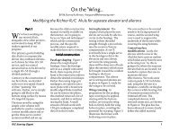
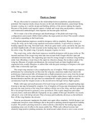
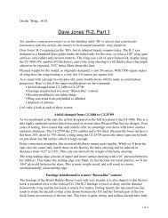
Of course there are additionalrequirements, but these are the majors.First of all, what appears important isthe advantage to cut the motor at lowaltitude. If you switch it off at 100mand all the other flyers at 200m, that isa 50 point difference if you made thesame flight length. (If all the <strong>com</strong>petitorsare making 10.00 minute flights and50 point landings, the first flyer gets1000 points and the second 550 / 600· 1000 = 917. That is 83 points less).In F3J, <strong>com</strong>petitors are fighting for 5to 10 points... Imagine what 83 pointsper flight is... F5J is the first time wherethe objective is not to be at the highestaltitude possible, nor to do it in theshortest time possible. We then haveto think differently. I will say “opposite.”Instead of trying to launch high, we haveto try to launch low. The plane mustthen have the ability to fly at low altitude,circling in the very small thermals youcan encounter at such altitude.Instead of being in a hurry, let’s taketime to go up and use the 30 secondsto reach the altitude and the locationyou think is good for thermaling. Youcan go 400m away (or even more) at theminimum altitude required to take thelift (for sure, you expect it is there). Asa consequence, if you want to increaseyour chances, your plane must be quitebig in order to be seen perfectly far awayand must be very easy to fly.For sure, F5J gliders must be differentfrom any other disciplines.This 30 second rule is the triggerrule of the discipline. It reinforces thestrategy aspect and the pilot ability tosuccessfully realize it.Exit powerful motors, hello light weightpropulsion set.So let’s be very open in our mind andchoices.This very first analysis reminds us thatthe flight has several phases and thateach of them does not have the sameinfluence on the final result. Determiningwhich phase is important and which oneis less or not important at all is a firstmandatory step in the design of a newplane.I have then split the F5J TD flight into fivephases.1. Altitude gain with propulsion2. Thermal search3. Altitude gain circling in thermal4. Return to the landing field5. LandingIn order to classify them, I propose toyou the following method:Compare each of them with the othersand give 1, 2 or 3 points to the one thatis more important. For example, Phase2 (thermal searching) is much moreimportant than Phase 1 (altitude gain withpropulsion). It takes a 3 rating.My personal rationale provides thetabular result shown in Table 1 at the topof the adjacent page.Of course, your understandings may leadto different notations. And this makes thediversity of our world.If we count points and crosses, thatprovides the results shown in Table 2 onthe opposite page.It is difficult to trigger “Thermal search”and “Altitude gain in lift.” Both phasesare quite equal. It is like chicken and egg.Which is first? It’s up to you to choose.My rationale is that the 30 seconds toclimb is also a time to go into the lift (orclose to it). So “thermal search” might beless important than “altitude gain in lift.”Of course you do not have to sacrifice alanding for an additional few seconds offlight. But the place of this phase meansthat you must find a thermal, take the lift,and go back first. Landing is in addition.6 R/C Soaring Digest
Table 1: The author’s personal rationaleIs more importantthanAltitude gain withmotorAltitude gain withmotorThermal search Altitude gain in lift Return to landingfieldLandingThermal search X (3) X (1) X (1)Altitude gain in lift X (3) X (1) X (1) X (1)Return to landingfieldLanding X (3)X (3) X (1)Table 2: Results of evaluation ofthe author’s personal rationaleAltitude gain in liftThermal searchReturn to the landing fieldLandingAltitude gain with motor4 crosses6 points3 crosses5 points2 crosses4 points1 cross3 points0 crosses0 pointsWeight = 24Weight = 15Weight = 8Weight = 3Weight = 0November <strong>2012</strong> 7
So our plane must be able first to find and take a thermal.Second, it must have the ability to return home even fardownwind, and then it must have the ability to land precisely.Each phase requires a specific ability that corresponds to aspecific plane parameter. So let’s define the trigger elements ofthe plane.Of course a flight occurs in a specific air condition. This mustbe defined first:• Speed of wind• Density of thermals in the field. Are they numerous, fare awayfrom the landing zone, upwind, downwind…• Thermal characteristics (force, size, catching altitude)• Turbulence of the air• Altitude of the field,• Humidity,• Ground and air temperature, sun• …In the design process, the plane will have to take into accountall those elements.The plane and its trigger elementsA plane is the result of alchemy. It is a <strong>com</strong>plex balancebetween several parameters more or less independent, more orless against or in favors the others.That’s why it is important to have a clear view of theirinfluences. (See Figure 2)We will define the plane thanks to physical parameters andaerodynamic parameters.Figure 2: Plane creation: A <strong>com</strong>plex alchemy.Physical parameters are defined by:• Span• Chords and associated distribution• Wing surface• Aspect ratio• Fuselage length• Fuselage maximum front surface• Tail surface (if any)• Fin surface (if any)• Rudder, flap, aileron, elevator sizes8 R/C Soaring Digest
• Weight of all elements and associated location in space andinertia• Profile(s) data (Camber, thickness and position in chord ofsuch…).• Tail volume• Center of gravity• …Aerodynamic characteristics are the consequences of suchphysical definitions on plane behavior:• Gliding ratio and speed associated• Minimum sinking rate and speed associated• Speed polar (Vz/Vx)• Yawing, rolling, pitching moment• Yawing, rolling pitching dynamic behavior (frequencies anddamping factors)• …Some of such parameters are real parameters, others are theconsequence of a conjunction of them and should be rejected.We then need to have a clear picture and analyze everything.So let’s look at the physical parameters that allow the accurateaerodynamic characteristic behaviors that <strong>com</strong>ply with ourclassification and air conditions.In reality, we will do the reverse:For each flight phase, we have to determine and optimize theaerodynamic characteristic that fulfills our classification andfind the associated physical characteristics that <strong>com</strong>ply with it.Altitude gain in liftIn order to optimize altitude gain in a thermal, we must firststudy the thermals - their size, location, altitude...Figure 3: A thermal can be modeled with few sinus functions.Realistic? Let say this is not so stupid. That’s a start of theunderstanding.In Western Europe, most of the thermals are quite narrow at lowaltitude. Let’s say that typically, the lifting air has a diameter of20m at 50m altitude. This will then be a reference for our planedesign.Their location and density in the field depends upon the fielditself - humidity, temperature difference, sun… Nothing to sayfor the plane except that in some cases you might require goingfar away to find them (so big plane, easy to fly). (See Figure 3)November <strong>2012</strong> 9
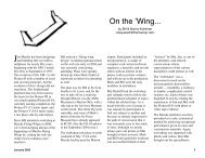
Knowing the thermals, then <strong>com</strong>es thestrategy to circle and take the lift.There are roughly three strategies:(1) Make a circle, estimate the center ofthe lift and make the next circle aroundthe estimated center…(2) Increase circling radius when the liftappears slow, relax the circling radiuswhen the lift increases in intensity.(3) Cross the lift, make a quarter turnaround the lift, cross it again, estimatethe lift in size and center and then circle.Studies have been made for drones inorder to optimize their flight duration.Different software has been tested tofind the better strategy. To this end,this depends upon the turbulencerate. Strategy (1) may be a bit easier inturbulent air.But what about our planes? Nothing andlots of things.First of all, you need to circle and thenhave the ability to continue circling. Buthow tight?Knowing the size of the thermals andtheir intensities, we can <strong>com</strong>pute thesinking rate of a plane circling and thenpredict if the plane is going up or down.This allows predicting the best bankangle to take the lift. This shows us that itFigure 4: The model of a lift is useful to estimate the optimum circling radius. For smalllift, the bank is more or less at 45°. Quite tight isn’t it?10 R/C Soaring Digest
is required to circle at high angle (more orless 45° in our reference case). Our planemust then have the ability to circle witha small radius in a very easy way. (SeeFigure 4)Of course, in order to take low intensitythermals, the sinking rate of the planemust be minimum (advantage to bigplanes and light planes).Circling ability and minimum sinking rate,that’s two important aspects.The circling ability is, at first, a matter of:• Wing loading. It must be as reduced aspossible• Cz. It must be as high as possible• Cz 3 /CX². This demands high lift andlow drag. Some thin airfoils wouldpotentially be required then.Despite what is usually believed, circlingability is not a matter of wing span.Make few calculations and you will seethat if you can reduce the circling radiusby a few percent, the climbing rate isincreased much more. Circling ability isthen the very important characteristic ofthe F5J category.To finally convince you, we had two<strong>com</strong>petitions this year where the firstor the second place was taken by amotorized F3K plane or an Easy Glider.Figure 5: The higher the aspect ratio, the higher the wing loading. It’s not for nothingthat birds like eagles have quite low aspect ratio. And it is also not for nothing that seagulls have a higher one. They do not fly the same air.November <strong>2012</strong> <strong>11</strong>
They where <strong>com</strong>peting against fullcarbon 4m planes with good pilots...What were the differences betweenthem: Ability in circling tight! This is alsoconfirmed byfull size glider experienceswhere for example, a Pioneer (full metalvery rustic plane, but very agile thanksto a long fuselage and which flies at lowspeed) was <strong>com</strong>pared to a Bocian (SZDplane with a 30% better gliding ratio andspeed). The first one was said as havingbetter thermal ability without doubt.Of course, we need to fly in the wind.We then can define a wing loading rangethat will have to be obtained to cover that<strong>com</strong>plete wind condition range. Let’ssay that standard wing loading (for the<strong>com</strong>plete plane) should be between 20and 30 g/dm².Since there is a direct link betweenaspect ratio and wing weight, the aspectratio should be as high as possibleto obtain the minimum wing load (i.e.the 20 g/dm²). It is then a matter ofconstruction techniques and propulsionequipment weight and no more a matterof aerodynamics. (See Figure 5)If you have studied thermals, you mustknow that at low altitude they are quitesmall. Circling may then be most of thetime at high angle of bank. This can beFigure 6: Blue and red curves are longitude and latitude. The plane is going straight.Light brown shows the altitude, the pink one is the speed and the green one is theyawing. As you see, even if the pilot tries to flight straight, the reality is a bit different.It is the conjunction of Dutch roll and phungoïde movement. All such movement(minimum V +/- 1m/s and yawing +/- 3 degrees) are very difficult to be seen withoutmeasurement devices.12 R/C Soaring Digest
feasible if, and only if, the yawing stability is optimum. In orderto illustrate this, I will say that the plane must fly like an F3Kone. As a consequence, the fuselage should be accuratelylong and the fin surface also accurately calculated. Here, it is amatter of dynamic behavior and no more a static one. Refer to<strong>RCSD</strong> late 20<strong>11</strong> for a better understanding.I can say, without much pretention, that actual F3J planesare not optimum in that concern (except for the SUPRA in itsoriginal configuration (1.4kg)). The fuselage should be longerand fin surface increased.Once again, it is not sufficient to have a very good wing tomake a good plane. If the plane doesn’t have accurate dynamicbehavior, the wing can not express its best. And the pilot cannot place the plane in a very easy manner at the right time inthe right position at the right speed. (See Figure 6)Tight circling and long fuselage have consequences on fin flapsize: When turning, the radius describes by the wing is not thesame than the one on the fin. This means that the natural effectof a fin during circling is to go against the turn. In order to havea turn without skid, it is required to have the fin in the directionof the turn. And the longer the fuselage is, the more importantthe action on the fin is. Of course, in reality, due to bank angle,the action is on both fin and tail. But the rationale remains. (SeeFigure 7)As a consequence, for a long fuselage, the rudder shouldrepresent 50% of the chord or even more. 60% should bepreferred.Circling requires also good low speed behavior. That meansthat the plane must have a speed range at low sink rate as largeas possible. If you <strong>com</strong>pare the Pike Perfect to the Supra, thePike appears better in this area (and worse in others of course).Figure 7: When turning, the tail describes a trajectory witha radius equal to “R0” but at a distance equal to “A + R0”.For long fuselage “A” is not neglectable (up to 20 cm). As aconsequence, the fin provides a torque in the opposite way ofthe turn. This requires fin action as if it was fully twisted from5° to 13°. For sure, the flap should be quite important for a 4mspan glider.November <strong>2012</strong> 13
Figure 8: Trying to find the best speed that optimised up wind or downwind conditions, the McCready analysis shows us a range ofspeed between 6 to 15 m/s.This is fundamental. I made speed measurements and it is verydifficult to fly at a fixed speed even with the speed informationin my eyes (I have a Xerivision system for my experiments). Evenin a straight line, the plane’s speed is varying from +/- 1m/s.This means that the minimum plane speed is much closer to thestall if the pilot expects to fly at Vzmin. If the plane speed rangearound Vzmin is not “very large,” it is absolutely impossible tofly at Vzmin. The plane has a good chance of stalling, especiallyduring circling.And the more the flaps are deflected (in a positive way), theshorter this range is. So caution with flap during circling.As a consequence, the F5J plane will have profiles with a bitmore camber than for F3J. Flaps should be used for transitionor speed reduction (circling in the core of the lift if stable).14 R/C Soaring Digest
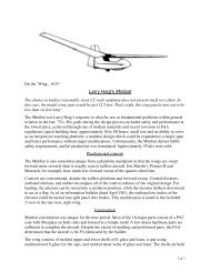
Thermal searchingDespite the pilot ability to read the air and the ground, the planemust be able to reach the thermal prior to being too low inaltitude.This means best gliding ratio and good ability to signal airmovement (so reduced inertia for the whole plane).As the number of days without wind are quite reduced(especially in my living area), the plane must have the ability tohave good gliding ratio between 7 to 15 m/s as it can be foundplaying with McCready approach taking into account sinking airand upwind flight.So profiles and aspect ratio should be optimized for such a kindof speed range.In F5J there is no requirement to have a plane that has goodbehavior at high speed. 100 km/h (28 m/s) or higher is only forfun. So keep it for F3J and other disciplines. (See Figure 8)Of course, in order to have good ability in circling and goodgliding ratio in the wind, flaps are required for high windconditions.The best possible gliding ratio is an alchemy that integratesprofile drag at a defined lift, induced drag, Reynolds number,stability...As a consequence, the profile thickness should be optimizedaccording to its camber, (this means try to reduce it in therespect of critical Re), and aspect ratio maximized. Both shouldintegrate the weight prediction for a defined load resistance.For sure, the wing span is an important factor. 4 m span allowsbest gliding ratio. And since the wing span is limited, be surethat winglets will appear in the next generation of plane.As written, it is alchemy…Figure 9: Return to the landing fieldReturn to the landing fieldReturn to the land field is not only a matter of best gliding ratio.The question is should the plane capable to return flight afterclimbing in a thermal?After climbing, the plane should be far away downwind at areached altitude. Should it <strong>com</strong>e back safely? (See Figure 9)This is then a matter of climb angle (a mix of climbing rate anddeviation to follow the thermal movement) and angle of descentupwind. The quicker the climb and the better the gliding ratioare, the higher is the chance to return home.The ability to take the lift gets once again its importance with allthe consequences on plane definition.November <strong>2012</strong> 15
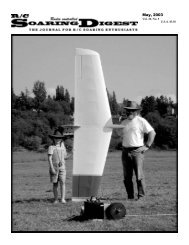
LandingLanding means reach the spot everytimes. Despite the pilot agility, the planemust have specific requirements:• Stop quickly when landing. In ordernot to destroy the propulsion unit, Iwould re<strong>com</strong>mend not to land as F3Jplanes. Since it is not possible to affixany stop feature, the only remainingsolution is a tail that continues underthe fuselage like for the AVA / BubbleDancer, F3K planes…• Have good maneuverability and goodstability in order to pass throughground turbulence and reach the spot.Maneuverability and passing throughturbulence without any affect arequite opposite. Since there are greatadvantages for all the other phases tohave very low inertia, the plane shouldhave very good maneuverability as<strong>com</strong>pensation.Here, it is a matter of rolling rate, brakingefficiency, descent angle at a fixedspeed. Consequences are on inertia, flapand aileron sizing, inertia (constructionissues are once again important…) andalso high dihedral in order that wing tipsdo not touch the ground prior landing...Classification of trigger plane elementLet’s take all of the plane parameters andestimate their consequences (in termsof advantage / disadvantage) for the fiveflight phases.Of course, for F5J, the first phase(reaching altitude) could be forgiven sinceit has no influence on the plane. Butthis is not the case for most of the othergliding categories.This provides the following table for themajors. But you can <strong>com</strong>plete it by anyparameters you want. (See Table 3)As you can see, there are threecategories of parameters:• The very important ones. In this firstcategory are found two dynamicstability parameters (on pitchingaxis) and only one static parameter(wing span). This means that despitewhat was usually admitted, the mostimportant thing is to have a very stableand well balanced plane.• The important ones. Quite close to thefirst category in terms of importance,are found other dynamic parameterssuch as yawing, inertia. Then are<strong>com</strong>ing what we can call the “standardplane parameters” (fuselage length,mass, profile curvature...). Once againwe have to point out the very highimportance of the dynamic behaviorfor a F5J plane. This is not the onlycategory that may have similarclassification. But very few planes arestudied in this way. AVL and XFLR5are here to improve our design.• The others. It is quite surprising to seeparameters like drag, gliding ratio,aspect ratio... at the bottom of theclassification. Is it so surprising? Lookat an eagle and look at a sea gull.Two birds, two types of flights, twoadaptations to an environment. Sodon’t be so surprised.After the Pasmespumas and theGenoma, here is my new F5J plane:The Genoma²After a first trial with a modified F3B (witha very long fuselage for good yawingstability) which shows the interest ofyawing stability calculation, I developeda series of profiles specifically for theF3J category. The idea was to promotespeed (and then small airfoil curvatureand very low thickness), high aspectratio (to <strong>com</strong>pensate the lower airfoillift by reducing the induced drag andlift). The objective was to be better thanthe Supra in speed and transition. Weconstructed it in a few exemples. I put all16 R/C Soaring Digest
Table 3: Aircraft parameters and consequences for five flight phasesNovember <strong>2012</strong> 17
of the information for the construction ona 200 illustrated pages (French languageactually only, sorry). For those interestedsee the website for more details. We measuredits performance and I have to confessthat this is quite a satisfaction to obtaina plane that corresponds exactly to thecalculation. I wanted it, I obtained it, andI love it. This plane is the best plane Ihave ever piloted. (I have constructedmore than 100 planes.) (See Figure 10)Then came the F5J category and Irestart from scratch my studies takinginto account new considerations suchas minimum weight for a defined aspectratio and G load, minimum circlingdiameter...This conducts me to the GENOMA².It is similar to the Genoma, but quitedifferent for some aspects:• Less aspect ratio to reach the 20g/dm²wing load,• higher camber for the profiles for lowerminimum speed,• lower minimum wing load,• more span (4m) to be at the maximumof the F5J regulation,• a new series of profiles takinginformation from the Pike perfect, theSupra, the AVA...Figure 10: The GENOMA as defined in 2010. It flies like a F3K plane with a 3.65 m span.18 R/C Soaring Digest
Figure <strong>11</strong>: Comparison polars• a new fin and tail to adjust dynamicbehavior.The objective was:• To improve speed range at low sinkrate in order to avoid stall duringcircling. In this respect, the Pikeperfect was taken as a reference.• To improve Gliding ratio betweenminimum sink and 15 m/s. The Suprais taken as the reference for thisaspect.• To improve low speed.• To have the same or even betteryawing and pitching stability than theGenoma.This provides me with the planformshown in Figure 12 (next page), with anassociated profile series (icons and linkson next page).The length of the fuselage is the sameas for the Genoma for transportationreasons, 2.2m long, that’s for me nearlythe maximum. Otherwise it is difficultto store it at home or in the car withoutrisk of damage... And I don’t want yet tomake a fuselage in two pieces.Dimensions are:• Fuselage from nose to leading edge:53 cm. Don’t think this is too much.When using a 105g / 700W gearedNovember <strong>2012</strong> 19
Genoma 2 Airfoil SeriesGenoma F5J 1: Genoma F5J 2: Genoma F5J 3: Genoma F5J SAUMON: Figure 12: Genoma 2 (<strong>2012</strong>)20 R/C Soaring Digest
motor and a 1300mA/h 3S Li-Pobattery (or even a 2200mA/h 3S Li-Po), this is not too much. This is justsufficient for the very long rear leverarm.• Fuselage from wing leading edge tothe end (fin trailing edge): 166 cm• Max section dimension of the fuselage:6*4 cm• Wing area: 85.56 dm²• Root chord: 26 cm• Aspect ratio: 18.7.• Max diameter of the boom = 34mm. Ofcourse you can reduce this diameter inorder to be lighter. But caution with thefuselage flexibility...Wing data and profiles:• Root: Dihedral = 3° - Chord = 26cm -Thickness = 7.8% - Camber = 2.9%• Root + 50cm: Dihedral = 3° - Chord =25cm - Thickness = 7.5%; Camber = 2.7%• Root + 100cm: Dihedral = 7° - Chord =24cm - Thickness = 7.5%; Camber =2.7%.• Root + 169cm: Dihedral = 7° - Chord =16cm - Thickness = 7.3%; Camber = 2.6%• Root + 190cm: Dihedral = 7° - Chord =<strong>11</strong>0cm - Thickness = 6.8%; Camber =2.4%• Root + 200cm: Chord = 5cm - Thickness =6.8%; Camber = 2.4%Flaps are 30% of the chord from theroot until 15 cm prior to the tip. Thenthe aileron is gradually reduced down to20%. Flap and aileron are “on the sameline” looking at the plane from the top.Tail:• Surface = 6.8 dm² (8% of wingsurface). But look at the <strong>com</strong>fortabletail volume.• Tail leading edge distance from wingleading edge = 1315 mm• Root chord = 12cm• Aspect ratio = 8.4• Tail volume = 0.47• Profile = HT-13Fin:• Surface = 7.4 dm²• Fin leading edge distance from wingleading edge = 1500 mm• Root chord = 18.5cm• Height = 55cm (including <strong>11</strong> cm underthe boom)• Profile = HT-13• 50% of the surface makes the rudder.This is a minimum. You can go upto 60% without a problem but withbenefits.The GENOMA² constructionThere are 20 moulds made for theGenoma. We planned initially 21, butfinally limited the number... Quite a lotI know. That’s why the Genoma wasstarted in a club. One guy is doing this,the other one that…We then succeed without much difficultyto create these moulds in less than 6months. And in one year of construction,the Genoma was flying. Of course, forthe Genoma² I reuse all of the moulds,even if the profiles are a bit different.The D-box is quite flexible so there is noadaptation problem.For details, look at the 200 pages (inFrench, sorry, but with lots of photos)written at www.xerivision.<strong>com</strong> (this is notmy website). (See Figure 13)Tail and finThe spar of the fin and the sub-fin isrealized with a carbon rod 3*0.8 mm onupper and lower side. The spar caps aremade with balsa. After it has been gluedtogether (Cyano), a Kevlar fishing wire isrolled around. Then balsa profile leadingand trailing pieces are glued. The trailingedge is made with a carbon rod 3*0.8mm and the trailing edge is coveredwith a small sheet of carbon (cut from aunidirectional 80g/m² carbon layer).The leading pieces are glued every 1.5cmand the trailing pieces can be gluedevery 4.5 cm. (See Figure 14)November <strong>2012</strong> 21
Figure 13: The Genoma² prior to recieving its <strong>com</strong>posite D-boxes. This is quite longto proceed but not very difficult at all. Nothing requires many tools (We used a CNCmachine for cutting the profiles, you can do without).Figure 14: Stabilizer (L) and vertical finand rudder (R) drawings.22 R/C Soaring Digest
Figure 15a and 15b: How to mould the D-boxes? Easy. On apositive mould. Not much science behind this. For the wing,two layers of Kevlar of 60g/dm² is fairly sufficient (the wing cansupport all aerobatic maneuvers). For tails and fin, a 60g/dm²kevlar is OK.The D-Box is made with a sheet of Kevlar (60g/dm²).Do not forget the D-box for the rudder. It has a very importantrole. 1.5cm large is sufficient.The secret of the D-Box is in the glue to assemble it. Thereis always too much glue! If you count at the end, this gluerepresents up to 25% of the total weight. Far too much for a solittle resistance. Try to reach 10 to 15% and you will be a king.(See Figures 16 and 17a and 17b)WingThe wing is a tail that is a bit bigger. That’s all… But thetechniques used are identical. (See Figures 18 and 19)The spar is made with two layers of carbon sheet 15*1mm atthe root. Then after 500mm, only one layer remains. The sparis also tapered down to 2mm at the tip.Leading profile pieces are glued (Cyano) every 2cm and thetrailing edges every 4cm.November <strong>2012</strong> 23
Figure 16: Tail and fin. Making them lighter and stronger isdifficult but possible. There are too many wood sticks in the fin.We can suppress 2/3 of them for the rudder. But this was forthe look!Figure 17a: Verticalfin and rudder andhorizontal stabilizermounted to fuselagebefore covering.Figure 17b: Vertical finand rudder and horizontalstabilizer mountedto fuselage aftercovering.24 R/C Soaring Digest
Figure 18: Wing planNovember <strong>2012</strong> 25
Figure 19: All balsa wood pieces have been realized on a CNCmachine. Of course, on request, files can be provided.Figure 20: How to mould the flap and aileron D-boxes — on awindow! Do not forget to “wax” it.26 R/C Soaring Digest
Above, Figure 21: Few detail of the wing to fuselage assemblysystem.Upper right, Figure 22: General view of the wing. The leadingedge is covered with paper for protection reason. It will be replacedby molded D-box.Lower right, Figure 23: View of D-box mold under process. Ontop, you can see the D-box bagged, in the center the D-boxresults and in the bottom of the picture the D-box mold.November <strong>2012</strong> 27
Figure 24: A view of the fuselage to better appreciate the design.Figure 25: The details on how to fix the tail. Verysimilar as the Supra / Bubble Dancer... Except thathere, everything is inside the boom. Everything ismade with very rustic moulds (and easy to be made).Nothing difficult!The leading edge D-box is made with2*60g/dm² Kevlar layers. This is enoughfor F5J. The standard 165 g/dm² Kevlarcarbonlayer is too much / too heavy forthis category.The flap and aileron D-boxes are cutfrom a 60g/dm² Kevlar layer that wasmoulded on a window… (See Figure 20)Nothing difficult. Everybody can do itwith a bit of experience or in a club. It isonly a bit long. (The wing requires moreor less 30 hours of work if you have theD-box moulds and the wing ribs alreadyprogrammed for the CNC milling!)But the result is... Magic! (See Figures 21,22 and 23)FuselageThe Genoma² fuselage is the same as theGenoma.Total length: 2.2mNose to Leading edge distance =530mm. This is not too much. I stronglyre<strong>com</strong>mend not to shorten the nose.Other dimension: Maximum larger =40mm, Maximum high = 60mm. Enoughplace to fix everything you want in termsof propulsion, batteries, servos... Thefuselage section is neither round norrectangular. We prefer an ovoid sectionas you can see in the pictures.Wing incidence is 4°, so that the planeflies with a horizontal boom.This is the flying attitude the Genomafamily has. And the fuselage of course28 R/C Soaring Digest
emains in this position with flap putdown or up.This horizontal attitude is for me quiteimportant to manage flight when theplane is very far away.Note: I usually play with the plane flying600m away (in our field this is wherethermals are).I confess that most of the F3x planesdo not have such incidence. But theirdesigns are based on speed. Remember,F5J is not F3J.The boom is horizontal and the nose hasa 2.5° pitch starting at the wing leadingedge. (See Figure 24 and 25)How does Genoma family fly?The Genoma (First) is quite magic. Youplay with it like with a F3K plane.Of course because of the wing span, itis a bit different. The rolling rate is lower,the gliding ratio is far better, but you dowhat you want when you want in a verysmall volume. I’m not a great pilot evenafter I playing with gliders for 40 years,but I still started to circle at 20 m altitudeduring the second flight.The next thing to be noticed is that it isvery easy to fly. For the last two years itis the plane I use for teaching new pilots.The trainees also learn how to land withFigure 26: One of my trainees with the Genoma after his flying lesson. They learneverything with it.it. I use an “Easy Glider” at the veryend of my teaching lessons in order fortrainees to know how to play with theirown future plane! (See Figure 26)Easy to fly means also easy to circle atlow altitude. As an example, I circle 10minutes between 20 and 50 m altitudeas if it was a normal flight. Thermal liftwas ridiculous, small, but of coursequite frequent. And this flight was madewithout any difficulties. I didn’t feelun<strong>com</strong>fortable at all during the flightnor exhausted after the flight even if theplane was 100 to 200m away from thelanding zone. (See Figure 27)One of my favorite ways to fly in athermal is to play with the “hand brake”when turning (like with the car): Whencircling in the downwind branch, therudder is put at its maximum. TheNovember <strong>2012</strong> 29
Figure 27: The proof that the Genoma can fly at very low altitude. And “No fear, nofun” is not my motto.ailerons are in the opposite direction soas to maintain a flat attitude. The planeis turning on its wing root, like a car withthe hand brake. A bit of pitch when beingupwind, then aileron order to restart theturn...When done in the very core of the lift,the plane has a “vertical” trajectory...Interesting, no?Another refinement I’m using now is thefourth axe management. I play with thecamber of the wing all along the flight.Instead of using pitching throttle (leftstick), I prefer to use the camber oneplaced on the right stick. The speedvariation is as with the left stick but theplane fuselage remains horizontal. Thisis marvelous during circling. You “push”when you are going upwind, and pullwhen going downwind. The pitching axisis used to maintain the circling radiusand the camber one manage the flightspeed. The plane then circles in a verysmooth and regular circle without havingmuch pitching order to be provided.And the fuselage remains in the sameposition (horizontal) which is once againfundamental to better feel the thermal.If you had used the pitch, the fuselageattitude would have changed due to yourpitching action… (See Figure 28)30 R/C Soaring Digest
Figure 28: The Genoma in flight. The fuselage doesn’t appear so long does it?November <strong>2012</strong> 31
In terms of yawing behavior, measuresand <strong>com</strong>putation are very close. Again,“Magic”! (See Figure 29)What about Genoma² flightThe new Genoma² is as expected fromcalculation.It flies as its older brother:• It is a F3K plane but with 4m span.This means that the way to fly it similar toany F3K plane with of course more inertia(more time to roll).• It has this ability to circle very shortly.And in this respect this open new wayof flying; On top of the standard “gentlecircling” way of flying with very smoothactions on the sticks that you need tomaster for TD flight, the Genoma familyallows to have a more aggressive wayof flying without much difficulty. Thisis quite useful at low altitude when thethermals are narrow and not very regular.Here, the yawing stability behavior is areal advantage <strong>com</strong>pare to any otherplanes.• It is a full aerobatic plane. Loop, roll,invert flight, chandelle are easy. The firstones (1 loop + 1 roll + 1 chandelle) weremade starting at less than 50m altitude…and of course finished by a landing closeto the pilot.Figure 29: Comparison of different planes in yawing. The Genoma (in light blue) is farbetter than any other planes (Supra original in yellow, Pike Perfect in purple, F3B planein dark blue) which provides it with very good circling ability. The Genoma² is of courseas its older brother.32 R/C Soaring Digest
Figure 30: First flight of the Genoma (First version) was in January 2010. Since that time, this 1.9kg plane flies every week withouttrouble. It even succeeds to flying three minutes alone (without any control due to an electrical problem) and crash in a field after a50m dive without any destruction. So light and so resistant!November <strong>2012</strong> 33
Figure 31: The man is 1.93m long. Quite a plane, no? The Genoma² weighs 1.6-1.7kg.It is 300g lighter than the Genoma for greater span and surface... The Genoma² is alsoable to make the barrel rollss in circles or any other aerobatic maneuver.• Stalling is difficult with a radio mix“Elevator” -> “Camber.” In such conditionthe stall is a 5m loss of altitude withrecovery after. And if you insist, it startsfor another cycle of stall/lost of altitude/recover. Then the only way to escape isto use the butterfly airbrakes.On top of this abilities are:• The potential wing load range of 19to 35g/dm² which is optimum to anyflight condition. As a consequence, thecircling radius (minimum 6m <strong>com</strong>paredto the 10m for the Genoma) and theminimum speed and sinking rate areimproved.• The sub-fin acts as a stopper duringlanding. The grass “sliding” is only50cm. That’s better than the 2m to3m for the first version. I wonderedwhether the fuselage and sub-finattachment will be strong enough.For “standard” and “nearly standard”landing (that’s what I made actually),nothing adverse happens.As already expressed, it is very difficultto measure minimum sinking rate or bestgliding ratio. It depends so much on airconditions that you can say one thingand it’s contrary. I then will not providevalues that don’t mean anything. Just tosay that with 30km/h wind, the Genoma²34 R/C Soaring Digest
without ballast stays in the sky with a“standard” sinking rate (as for any otherplanes for such wind that obliges tofly at best gliding ratio and not at bestsinking rate). Of course, with such wind,it is re<strong>com</strong>mended to have 500g to 800gballast for better penetration / glidingratio. In this case Genoma and Genoma²are quite equivalent. Differences couldnot be measured for me.The Genoma² in its first TD F5J contestAfter only two flights in 30 to 40 km/hwind, I made an F5J contest. The planehad never been ballasted, circling hadnot been tested, flap <strong>com</strong>pensationwas not well triggered, airbrakes andprecision landing never tested.Because F5J is a new discipline, only fewcontests occur in my area. I had then toparticipate.I also have to state that I’ve only made<strong>com</strong>petitions two times in my life. Thefirst one was in 1980 (I finished last) andthe second in 1982 (I finished third butwe were only three <strong>com</strong>petitors and Icrashed my plane on the first flight). So,in reality I consider that it was my realfirst Thermal Duration (TD) contest.Because of the pressure and the veryfew number of flights with the Genoma²I wanted to start with the Genoma. ButFigure 32: The Genoma² (facing the camera) and the Genoma ready for flight.November <strong>2012</strong> 35
then the first failure occurs during aflight test: a flap servo failed. ThanksMister Murphy! I then have to fly with theGenoma² which you will recall had onlytwo flights since new... Not a good wayto start a TD contest.Other <strong>com</strong>petitors had made<strong>com</strong>petitions for years (F3J, otherTD types...). Gliders used were PikePerfect, Maxa, AVA, Shadow, Electra,Graphit, Alfa club and homemade planesincluding the Genoma².Conditions were good with low wind(10 to 25km/h wind) which obliged thelightest planes (Maxa and Genoma²)to ballast a bit when the wind went up(+ 250g). The AVA didn’t have ballastcapability which was a disadvantage insome flights. All other planes had wingloadings between 27 and 35g/dm² anddidn’t require ballasting.I was then quite impressed and anxiousfor the first run.I then flew and discovered that the planeis very good, and even without thermals,did equal with the others. My first landingwas not so good because I didn’t knowhow the plane reacted or how to land ona spot...Then all the other seven flights proved tome the following:Figure 33: Genoma² for its first flight. Except few adjustments, it flies perfectlyand I found immediately <strong>com</strong>fortable. It is even better in circling ability due to thepossible low wing load (19g/dm² without ballast). Of course things needs adjustment(<strong>com</strong>pensation, trim…).36 R/C Soaring Digest
1) The Genoma is better than any othersin circling. It flies like an F3K plane andof course can also fly like an F3J plane.This ability to circle in an aggressive wayin a very low volume is a real and majoradvantage for a TD <strong>com</strong>petition. Andthen, my analysis in this respect is reallyvalid. With thermals, the plane alwayswent over the others or at the samealtitude. The Genoma² opens a new flightenvelope <strong>com</strong>pared to existing 3m to 4mspan gliders. And I’m not an expert inthermal hunting!!!2) Transition: The plane is as good asthe others. I didn’t play much with flapduring transition because of the flap<strong>com</strong>pensation adjustment was notcorrect. But I’ve never been trappeddownwind as the AVAs were. What Ican say is that the higher camber ofthe Genoma² wing indicates you needto play with the flaps if you want to beas good as a Maxa for example. Andof course, a full moulded wing made inaccurate moulds are always better thana handmade one. But once again, thecosts are very different and for the price,the Genoma² is really good.3) I discovered how to land after the TDcontest when I offered other <strong>com</strong>petitorsto fly the Genoma². It is finally verysimple. Plane has to transit back to thespot in order that it reaches a 2m altitude5m in front of the spot. Then full brake.The plane stops in the air, pitches andfalls like a parachute at low and constantspeed. It remains agile on all axes andyou can adjust the spot. At the very end,pull on the elevator stick and the planelands flat. The under fin and the lowspeed immediately stop the plane. As theEnglish say “it’s a piece of cake” if youhave a few practice sessions.4) Concerning the sinking rate, it is asgood as any others. With real mouldedwing it will be a must for sure!So my landing was not good at all. Twooutside, one at 1.2m, the others between3 meters and 5 meters.I knew I obtained 1000 points for onerun. I miss another one for a stupidmisunderstanding with my caller (Ithought that only two minutes remainedand exited the thermal — I was 100mover all the others — and start myapproach back... When I reach 180maltitude (50 m lower than others), Idiscover that 5 minutes of the flightremains... And no more thermals exceptvery narrow ones... So I get an 8 min 40second flight.And finally, I finish the contest in thirdposition... Good for a start isn’t it?So despite the inability of the pilot tomanage the sticks correctly, the planehas real potential.ConclusionYawing stability is fundamental for ourplanes. This was not calculated in thepast due to lack of knowledge and tools.But thanks to M. Drela and A. Deperrois,this is no more the case. This could beapplied to all our disciplines. Aerobaticplanes and F3K already do it. For thosewho play other games, you can alsoapply the yawing stability calculationprinciples. As an example, I made aracing plane with good results. (SeeFigure 34)Making our own model is still possible forF5J planes. It’s not a matter of expertisebut only a matter of time to construct it.This means that this discipline has roomfor experimentation and that you are notobliged to spend $1000 to $2000 to get asingle plane.The cost of the Genoma is about $400without equipment. And if you make itin a club, this cost of course could godown.Yes, this is quite more expensive thanmaking an F3K plane, and then we needto make calculations to predict the resultprior to launching the building phase. ButNovember <strong>2012</strong> 37
Figure 34: A small racer (1m span, 300w only) where the fuselage length is longerthan the span. Despite the fact that this configuration disturbs our minds, it is not sounusual for real racing planes. The fuselage increase allows us to reduce fin and taildimensions (and then drag) and to increase the stability. Flight is like an arrow —”on arail.”the flying envelop of a 4m span plane isalso far more extended!The Genoma² has been createdtaking into account 40 years of glidingcalculation experiences, 100 planesconstructed (most of them werehomemade) with about 25 years forelectric TD planes including some forduration records. The Genoma familyhas already made one to one TD flightswith good results. The first <strong>com</strong>petitionresult is also quite encouraging. Youmay say that this could <strong>com</strong>e from thepilot itself. But my experiences (andespecially my first <strong>com</strong>petition) show methat it is mainly due to the plane itself,and especially to the yawing stability. Ofcourse this doesn’t mean that it is thebest plane.If you are satisfied with a defined wing(even I think that the Genoma² is moreaccurate for F5J, I will never say thatactual F3J wings are not good for F5Jcategory), you can then improve yourplane by redesigning a fuselage and a finand rudder for accurate yawing stabilitybehavior. This is then far cheaper thancreating a new plane. And tools likeAVL or XFLR5 are here to guide us. Thiswill force the builder to propose realgood planes and not planes that have38 R/C Soaring Digest
In a future issue of RC Soaring Digest...<strong>com</strong>mercial interests and fashion behindthem.For those who want to have an up to dateF5J plane, the Genoma² is the one youexpected. You can then either:• Copy the Genoma² with the same orsimilar standard construction (woodand D-box),• Or use the Supra published buildingtechniques and construct yourGenoma²; this will of course workperfectly,• Or make some moulds with a CNCmachine.If you make moulds (be sure that it isreally feasible for a non professional guyto have a plane as light as the publishedversion), I of course encourage you to doso. Only advise me in order to see howI can get one of those wings. Thanks inadvance.We have seen that wing loading is verylinked to aspect ratio. This means thatif you do not want to have a plane at20g/dm² without ballast but somethingmore closed to 25 to 30 g/dm². You canplay with this parameter. One possiblesolution is then the Genoma firstgeneration.So let’s fly F5J!Walk-around: Tony Condon’s Niedrauer NG-1Jerome Niedrauer built this glider in the early 1970s with the goal of reducingdrag and increasing the performance of a stock BG-12. It is now owned by TonyCondon who says, “The NG-1 is the latest addition to the Condon family gliderfleet and is an interesting collection of Briegleb BG-12 and custom made gliderparts. Most people can’t figureout what it is at first glance, and the best shortanswer I have heard to describe it is simply “Experimental.”November <strong>2012</strong> 39
Reviewfrom RCRCM and OleRC.<strong>com</strong>Andy Page, 40 R/C Soaring Digest
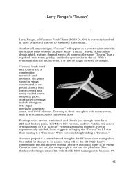
From designer/pilot Carlos Pisarello ofArgentina <strong>com</strong>es the Toba, a new modelfor F3B multi task soaring, F3F sloperacing, and electric assist soaring. Builtby RCRCM in China, the Toba is anaffordable sailplane. But make no mistake,it is also a well built model and that makesit a great value. Tobas were flown by theChinese team at the 20<strong>11</strong> F3B WorldChampionships in China. Wing layupoptions are carbon D-tube and full carbon.The review model, supplied by OleRC in Hong Kong, isthe full carbon version.What you getIn addition to the airframe, RCRCM supplymachined plywood servo frames for flapand aileron servos, servo covers, flap hornfairings, a ballast tube (for F3F fuselageonly), a servo tray, wire harness withMultiplex-style 6-pin connectors, carbontube pushrods, clevises, wing pushrods,and a towhook.The frames are sized for MKS DS6125servos but with small modifications canbe made to work with any thin wing servo.This is a nice accessory not often includedand the use of wood makes them easilymodifiable for versatility.Oddly, the towhook <strong>com</strong>es unassembledand with quite a loose fit of the unthreadedsteel hook in the aluminum plate. Isubstituted one of the readily availableunits from Kennedy Composites.Specifications and WeightsFrom the manufacturer’s website:Wing span: 3085mmLength: 1456mmWing airfoil: RCRCM2010-8Wing area: 58dm2Tail airfoil: RCRCM2010-10Flying weight: 2000-2100gReview model <strong>com</strong>ponent weights in grams:Left Wing: 747RIght Wing: 745Left Tail: 50Right Tail: 50F3B Fuselage with nose and tail cones: 208F3F Fuselage with nose and tail cones: 215Wing Joiner: 104Ballast Tube: 25Servo Tray: 14Wire Harness: 79Servo Frames (4): 16Servo Covers / Pushrod Fairings (6 pcs): 9Tail Joiners (2): 6Carbon Tube Pushrods (2): 31 (when cut to required length)The total F3B airframe weight without hardware or radio gear<strong>com</strong>es to 1910 grams, or about 67 ounces.For those of you who wonder about such things as weightdistribution, the wing panel CG (finished with servos, covers, andwiring) is at about 40% of the half span.November <strong>2012</strong> 41
First impressionsLike anyone else, I could not resistputting the parts together for the firsttime immediately after unpacking andwas pleased to note that both the designand execution of this sailplane are welldone. All of the joiners fit precisely rightout of the box - a good sign.While these are purpose built tools forserious <strong>com</strong>petition, it isn’t all aboutmechanics and performance. We likegood looking airplanes too and theToba does not disappoint with its veryattractive lines. All the molding is verycrisp and smooth. The graphics andcolors are striking and not just the sameold thing.Breaking it down again I moved on to acloser inspection. The molding qualityis very good with clean and smoothedges. There is some visible telegraphingof fabric weave and spar edges on thewing panels but nothing unusual orconcerning.The elevators and ailerons stop short ofthe tips, leaving a small vulnerable areathat could be easily damaged. In factone of the tail tips was slightly crackedalready. A drop of thin CA fixed that. Careduring transportation and handling willbe needed to keep these intact.Available space for aileron servos is tight.This is a thin wing, measured at 8% atthe root. If using the supplied covers,Completecontents laid outfor inspection.Right out of thebox. What a greatlooking sailplane!42 R/C Soaring Digest
Above: Flap wiper and pushrod fairing recess.Above right: Top hinged aileron wiper. Lower skinrecessed for servo cover with integrated pushrod fairing.Right: One of the smoothest molded leading edges I’veseen. No ridges, no pits.Below: Wing root. Middle pocket is for ballast.November <strong>2012</strong> 43
Supplied flap and aileron horns. Two of these escaped duringshipping. Probably would work just fine, but I elected to makethe replacements a bit larger for more substantial attachment.Final parts ready for installation.any of the typical aileron servos will fit.But if you wish to substitute flat coversyou have very little space to work with.The inside height of the bay is about15/32" at the forward edge and only5/16" at the aft edge. Space is of coursemore generous in the flap servo bay,with 13/32" of height at the aft edge.Airtronics 94761’s fit nicely there.Unlike most <strong>com</strong>posite sailplanes thesedays the ailerons are top hinged andintended to be driven with an externallinkage. It may be possible to run thelinkage inside but I used the stock setupand covers. Flaps are bottom hinged.The wipers are some of the best I’veseen with very tight tolerances to the skinwith no interference. Hinge movement isvery good with plenty of range of motionand no binding at all.Two fuselages were supplied with thereview package, for F3B and F3F. TheF3B fuselage is very small in crosssection and sets the wing at a positiveangle of incidence. The F3F fuselageappears to have zero-zero incidencesettings and is sized about 1/10" tallerand wider in order to ac<strong>com</strong>modatethe ballast tube. Only one servo trayand harness were supplied. We did notbuild out the F3F fuselage as of the timeof publication, though other than thedifferences noted above it is identical.The large cross section carbon wingjoiner is typical for a two piece wing. It’shollow, with two spaces on each endthat can be used for ballast. It may nothave much practical effect but the depthof the cavities on the subject joiner varyby about an inch left to right. Additionalballast cavities are molded into the wingroots. It should be possible to tailor theballast to load it up without changing theCG. By my rough calculation there is alittle less than 9 cubic inches of volumetotal in all cavities which would give amaximum possible capacity of about 43ounces of brass or 59 ounces of lead.Tailoring for CG will likely reduce themaximum possible weight.The wing skins are not pre-cut for flappushrod exits or for horn installation.Supplied horns are glass and seemrather small for secure attachment.Two of them were lost in shipment,however, so I had no choice but tofabricate new ones. The hardware waspackaged in thin, fragile plastic bagswhich had broken open, and the box wasconstructed so that small parts could44 R/C Soaring Digest
easily escape. Those lost horns mightbe doing endless speed runs across thePacific in the belly of a 747.The removable nosecone is glass butthere are four strips of approximately 1/4"wide carbon running through the nose ofthe fuselage itself. About 4" forward ofthe aft end of the nosecone the fuselagetransitions to all carbon. The nose isopen on the bottom rather than the top,keeping the pushrods clear of the wingjoiner and your antennae on the best sideof the mass of tightly packed radio gear.The BuildFirst the flap pushrod exit was createdby using a straight Dremel bit to cut theupper skin. The skin is molded with arecess for the pushrod fairing so thereis no guesswork here, just cut it backleaving a small ledge for the fairing.Next, deflect the flap all the way downand relieve the auxiliary/shear spar usinga small Dremel sanding drum. The samedrum works nicely for relieving the flapwiper.Since I wanted to make the flap horn abit longer than stock for the strongestpossible connection, I opted to first testfit a pattern cut from 1/64" ply beforecutting the circuit board stock.First I cut a squarish opening in the flapshear web using a #<strong>11</strong> blade. A couple ofeyeballed trials using scissors to cut theNow, all you seasoned experts out there already know this, butit might be worth mentioning some tools that are handy for anymolded sailplane project that might not be in the typical modelairplane shop.• Riffler files are great for precise access in tight spaces, usefulhere for roughing up the inside of the nose for gluing in the tray.They’re also indispensible for shaping details in <strong>com</strong>posite repairssuch as around wing root fillets.• Chainsaw files, in several small round sizes, are cheap andreadily available at any hardware store. Their sharp, fine teethhappen to cut our materials very well. I reach for these moreoften than any other type of round file. They can do very preciseshaping of balsa, plywood, <strong>com</strong>posites, and of course metals. Ifyou cut the smooth end off with a cutoff wheel you have cuttingteeth right at the end where you often need them.• Woodworking chisels and a small flush-cutting Japanese sawmake quick work of precise trimming of wood parts, especiallyplywood. I used them to enlarge the openings in the thickplywood tray.This is the only source I could find that has a photo of theJapanese saw. It’s in the UK: .This is te same saw from a US source: .Look for a specialty woodworking store in your area and you’llfind many things well suited for model airplane use that you justwon’t find at hobby shops. For example, the best old schoolhardware and hand tool store in Seattle and possibly anywhere isHarwick’s in the University District. There’s not much on their siteyet but there is an incredible selection in the store: .November <strong>2012</strong> 45
Opening the upper skin for flap pushrods.Auxiliary/shear spar cleared for pushrod. Flap shear webopened for control horn.Making a template for the flap control horns.Checking for clearance and range of motion.46 R/C Soaring Digest
Flap horn installed.Flap pushrod installed. These are Sullivan clevises and 2-56threaded rods rather than the supplied hardware.ply and I had the right shape to fit insidethe flap and contact both the upper andlower skins. Tracing that wedge shape tofresh ply stock I added the horn as a bestguess. After a little trimming to makesure it fit under the fairing and wouldprovide the required range of motion, itwas done. Make sure it doesn’t hit thelower skin when deflected for up flaperonmovement. The final template is shown inthe photos.The circuit board stock was cut roughlyto shape with a Dremel cutoff wheel thenfinished with a disc sander and files.Aileron horns were done similarly but didnot need the leg to fit into the surface.They are just a standard triangular shape.Thickened epoxy holds them all in.The remainder of the wing work willbe familiar to anyone who has done amolded model.Servo frames are glued in with thickenedepoxy, with the servo mounted in theframe after first wrapping with Saranwrap. Be sure to tighten the screws justas you will when securing the servos forflight, do not weight them down duringcuring, and allow plenty of time for cure.I like to do this step first so they can curefor a few days while I do the rest of thebuild. A little care during this step willeliminate any telegraphing of the framefootprint through the skin.November <strong>2012</strong> 47
Aileron horn installation. Lower skin and wiper relieved for clevisusing sanding drum. Shimmed wire ensures the same geometryfor equal movement of both ailerons.Airtronics 94761 flap servo in frame being glued in place. Servois screwed in tightly, protected by Saran wrap.Aileron horn installed.Clip a short servo extension and attach it to music wire withheat shrink tubing for an effective tool for fishing wire harnessesthrough wings.48 R/C Soaring Digest
Multiplex 6-pin connector. You may wish to pot this into thewing. I chose to leave it loose. There is just enough length in thewire harness to allow disassembly without yanking on the wires.Twisting the knife: the easy way to drill holes in<strong>com</strong>posite skins.Drill a few more holes then clear it out with a chainsaw file.A little alcohol on a glove allows neat smoothing and shapingof thickened epoxy, here to firm up and protect the wires wherethey’ll be handled during assembly/disassembly.A flat file cleans it up the rest of the way.November <strong>2012</strong> 49
Fuselage connectors can be glued against molded recesses in the wing root.Laying out radio gear. Space is very tight so plan ahead for clevis clearance and nose weight.50 R/C Soaring Digest
There really is nothing to do on the tailsunless your horns need to be reglued.One of mine was not very secure andpulled loose. It was roughened witha diamond file and reinstalled withthickened epoxy. Be sure to give thema good test and correct the glue jointif you’re at all in doubt. You do have torelieve the tailcone for the elevator hornsusing a small sanding drum.The supplied fuselage tray is widerthan the F3B fuselage so that it can beused with either version. I used a pieceof sheet balsa fitted to the nose as atemplate to reduce the amount of trialtrimming of the 1/4" ply tray.No guidance is provided for locating it.Beware that you may need to leave morespace up front for balance weight thanyou think! At the location shown, my trayleft just enough space to balance themodel at a neutral CG, and that is witha four cell battery pack (Elite 1500mahNiMH).Put the tray as far back as you can,allowing just enough room to workwith the aft servo pushrod. The servoopenings are slightly smaller than neededfor the Airtronics 94809 but there issufficient material to fit two of them.Height and width inside the noseconeare very limited so plan carefully. I leftjust a little space at the ‘bottom’ of theservos and put them on the centerline,resulting in near zero clearance betweenthe clevises and the nosecone.If using the stock pushrods you willneed to support them midway down thetailboom. I used a block of stiff foamrubber cut roughly to the fuselage crosssection shape and about an inch long.Holes are easily drilled in it by twistinga metal tube with a rough sawn end byhand.You could shove the foam block downthe boom with a stick and hope theholes stay properly placed and sizedto avoid binding the pushrods, but Iadded aluminum tubes (from the stockused to drill the holes) to the foam, thenused the pushrods themselves to guidethe assembly into place. The tubesare longer than the foam to help avoidgetting epoxy on the pushrods duringassembly and added less than a gram.One O-ring CA’d to one pushrodprovides a stop for pushing it into place.Just make sure the O-ring is placed soas to not contact the tube during normaloperation.After masking the accessible area insidethe nose I smeared some 5-minute onthe foam and in it went. The result isfrictionless movement with no slop dueto buckling of the bendy pushrods andvery little added weight. All this is bestdone before adding anything else to thefuselage.My calculations show a possible savingof just about one ounce overall bychanging to .07" carbon pushrods inteflon tubes, taking into considerationthe reduction in noseweight as well aspushrod weight.Although you could use the suppliedpushrod hardware, I substituted Sullivan2-56 clevises and threaded rod. I find theSullivan clevises just fit better and staytighter on threaded rod than other brandsof metal clevises. The popular Hayesplastic clevises may not fit in some of thetight spaces on this model.After first flights I usually put a drop ofblack CA on the threads to lock them inplace.Initial SetupI eyeballed the CG to a point about4" from the wing LE. RTF weight withstock build and this CG is 88.5 Oz. Notethat this is the full carbon version. It isnot known how much weight can besaved with the D-tube layup. My initialcontrol surface throws were as follows,measured at surface roots:Elevator 1/2" up and down.Rudder 1/2" left and right.Aileron 3/4" up , 1/2" down.Flaperon, 25% of aileron movement.Flaps, about 60-70 degrees max forlanding mode.November <strong>2012</strong> 51
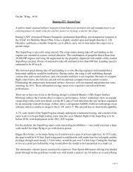
Launch flap, a conservative 1/2". It willneed more to pull hard.Float, Cruise, and Reflex set to thestandard “little bit down, flat on the lowersurface, and a little bit up.” Lackingpublished settings, these will work andthings will sort themselves out during thefirst few outings.Flying the TobaBefore we did the range check I hadbeen somewhat concerned about thecarbon strips and tightly packed gear inthe nose. This proved to be unfoundedthough because we had no issues withrange using an Airtronics 92104 receiverwhich did its job flawlessly as always.After a quick jog to see how the modelfelt with some airspeed I did a few handtosses. Elevator setting was spot onand the throws felt fine. So up the lineit went, tracking straight and behavingas it should. The full carbon wing is verystiff, giving a precise feel to the handling.Subsequent flights showed the CG to beneutral. Actual measurement puts this at4 1/8" from the wing LE, or 105mm.The obligatory pre-maiden photo. Andywith the newly finished Toba. Noticethe slim nose, typical of modern F3Bmachines.52 R/C Soaring Digest
TOBA DETAILSNovember <strong>2012</strong> 53
Running through a few quick tests Ithen checked out the handling, stallcharacteristics, and pushed the limits alittle to see how it responded.With the model pointed away from meI rolled it back and forth a few timesquickly to see how the nose tracked – theold roll-around-a-point exercise.With the above settings and about 40%rudder mixed to aileron input the Tobatracked straight with no adverse yaw.Roll rate was crisp, just how I like it.54 R/C Soaring Digest
I was happy with the CG so I set elevatortrim for float and cruise modes thenplayed around with stalls. The Toba hada lower stall speed than expected andshowed no bad habits.Next was to see how it reacted to a bitof abuse. Starting from a moderately fastspeed I cranked it up hard into a steepturn. Toba was right at home, retainingenergy nicely through several revolutions.Forcing a high speed stall in that attitudeagain showed the forgiving handlingqualities. The recovery was immediateupon proper pilot input.Setting up for a landing, I pulled flaps tocheck the elevator <strong>com</strong>pensation mix.I’d programmed in a guess which was anearly linear curve with moderate downelevator travel, and that proved to be agood place to start. As expected, theflaps are very effective with about 60-70degrees of maximum travel. That is morethan enough.This is a much heavier model than I amused to, with a wing loading of 14 oz/ft 2 , yet it floats and goes up in lighter liftthan I expected. The crisp handling andwide speed envelope should be an assetfor the task soaring it is designed for aswell as make for a fun sailplane for big airdays at the thermal field or slope.November <strong>2012</strong> 55
56 R/C Soaring Digest
November <strong>2012</strong> 57
58 R/C Soaring Digest
ConclusionThe Toba was one of the most trouble free,straightforward molded sailplane builds I’vedone. There is nothing tricky or <strong>com</strong>plicatedabout the build and nothing significant needsto be reworked, though you may choose to uselighter pushrods or your own control horns.This is a lot of sailplane for the money and Ilook forward to flying it more!Resources:OleRC:Toba:Airtronics:Pushrods, towhook, etc.:November <strong>2012</strong> 59
KST DS125MG servoBill & Bunny Kuhlman, bsquared@centurytel.netThe KST DS125MG is a thin, metal gear, digital servo. It isdesigned and configured to be used to drive ailerons and flapson 2-servo, 4-servo or 6-servo wings.During our evaluation, many <strong>com</strong>parisons were made with theHitec HS-5125MG, a similarly sized servo with which we areextremely familiar, having used them extensively over the lastfew years.Our sample was provided by OleRC in Hong Kong and arrived in the usual retail cardstockbox and was enclosed in a bubble packet. Included with theservo were three plastic servo arms, a blue anodized aluminumarm, three mounting screws and the servo arm set-screw asshown in the title photo.The body of the DS125MG is primarily machined aluminum.There is a molded plastic portion which sits at the base of thegear train. The case itself is very reminiscent of those producedby Volz for model aircraft use - the flat sides of the motor areflush with the case surface.All of the gears in this servo are metal. There is no play in thelinkage and the sound in operation reflects the sturdiness withwhich this servo is built. Operation is extremely smooth and themeasured travel with signals from 1.00μsec to 2.00μsec wasslightly more than 90 degrees.In our testing, centering was consistently right on with no load,and deviations of about 1/8th inch were measured with a loadof 48oz.in. (It should be noted that the nylon control armsdeflect substantially under this load as well.) With a 5-cell NiMHpack, current draw is approximately 230mA with a load of24oz.in, and 850mA with a load of 48oz.in. The maximummeasured current draw, 1.2A, occurred under full stallconditions.Because the DS125MG is slightly taller than the HiTECHS-5125MG and like servos, it may not be able to be used asa direct replacement in most installations. For new installs,wood frames need to be made slightly longer because ofthe placement of the two “ear” holes. The KST DS125MG is3gm/0.12oz heavier than the HS-5125 but is rated at about50% more torque, so will be an advantageous choice in someapplications.Sources:OleRC:KST:60 R/C Soaring Digest
DimensionsW x T x HRated torqueKST DS125MG30mm x 10mm x35.5mm1.185" x 0.395" x 1.414"4.8 Kg.cm, 66.66 oz.in@ 4.8v5.80 Kg.cm, 80.55 oz.in@ 6.0vOperating speed 0.15 sec/60° @ 4.8VCase material0.12 sec/60° @ 6.0VMachined aluminum andmolded plasticHiTEC HS-5125MG30mm x 10mm x 34mm1.185" x 0.395" x 1.332"3.0 Kg.cm, 41.7 oz.in @4.8V3.5 Kg.cm, 48.6 oz.in @6.0V0.17 sec/60° @ 4.8V0.13 sec/60° @ 6.0VMolded plasticWeight 27g, 0.95oz 24g, 0.84ozBearings Dual ball bearing Dual ball bearingGear materialBronze and steel withsteel output shaftRetail price $45.00 $50.00Nylon, steel and bronzewith steel output shaftKST DS125MGHiTEC HS-5125MGNovember <strong>2012</strong> 61
SOARFEST 201323//24 February 2013 at MatamataOfficial Entry Form** Entries Must be received by 20-02-2013Two Payment Options :1. Snail-mail - with Cheque made out to AucklandSoar Inc. to:Soarfest36 Ripon Cres Meadowbank Auckland 1072Email Aneil Patel (doing Matrix) at : aneilp@orcon.net.nzorTed Bealing at : ted@pl.net once the entry is in the mail.2. Pay online to the club bank accountNational Bank, Onehunga. A/C No 06 0209 0085092 00Email Aneil Patel at : aneilp@orcon.net.nz or Ted Bealing at : ted@pl.netonce the payment has been made.Name : ____________________________________________NZMAA Number :________________Frequency 1 : _______________ Frequency 2 : _______________Open (Entry Fee $20.00) Sportsman (FREE Entry fee)Saturday Night BBQ (Details T.B.A)All entries MUST BE RECEIVED and FEE/S PAID by 20 February 2013Email entries accepted up until 8 pm on the 20th February – NO Later. Entries only accepted on the field if there are no frequency clashes and an available slot is left in the matrix Please also provide an Alternative FrequencyIf you cannot change frequencies – you May Not be able to fly. Event to be a Hybrid of Premier Duration/F3J.By entering this contest I agree to abide by the Rules and Regulations as set out by AucklandSoar Inc, theContest Director or the Contest Protest Committee.I agree to and accept the above conditions.________________________________________(Signature)62 R/C Soaring Digest
World Soaring Masters <strong>2012</strong>Text by Mike Reagan, mdreagan1@gmail.<strong>com</strong>Photos by Mark Nankivil, nankivil@covad.<strong>com</strong>November <strong>2012</strong> 63
Hey guys, I thought you might like a littlereport on this years masters. If you werenot there you missed one of the bestcontests in a long time. I have been to allfour of the Muncie based Masters andflown in the flyoffs twice, which means Ihave flown 58 rounds, which gives me agreat perspective from which to observethe <strong>com</strong>petition. This also means I havebeen burned and done a little burningmyself.Every kind of condition existed this yearfrom dead calm to 30+ mph winds,rain, cold, you name it. This was a realtest of man and machine. Aspires werethe plane of choice and in the wind gotgreat launches and penetrated well.However, the few times the wind was notblowing put them at a big disadvantageagainst the light weight Maxas and superlight Explorers. Being at the optimumballasted weight was crucial to doing wellin every round. Being too heavy meantthat getting that great save or climbingwith the group was almost impossible.Being too light meant you could climbout only to get way down wind with noway to get back!Having a good caller was also critical,made even harder because of the shorttime between groups, and the randomorder made sure you had to get someonedifferent to call almost every round.Trying to follow other planes down windled to many land-outs in the beans64 R/C Soaring Digest
(zero) and planes landing miles away aspilots pushed the limits of their visibilityand underestimated the wind and theirplanes ability to get back, which wasnecessary many times to get that max.I flew twice WELL past my <strong>com</strong>fort zone,but did get my time! Many low saveswere made throughout the contest, nevergive up was the order of the day.Ben Clerx and Jim Fricky made greatsaves during the finals, but the best savewas done by Joe. 20 ft. high downwindover the beans, no hope, a puff camethrough. Zero gain the first few turns butslowly developed into great lift, climbingout to the clouds.I was timing another flier in this groupwho made his time easily hooking upright after launch. As Joe said, you musthave screwed up to be in that position inthe first place. It is much more fun whenyou make those low saves, though!The fliers helping each other wasamazing. On one of my rounds I grabbedmy plane to go fly and when I turned onmy transmitter I got the blank screen ofdeath, done, after all that expense andeffort. The Horizon boys soon foundout and diagnosed the problem as adead battery. Before I knew what washappening I had a new battery and wasup in the next flight group ready to rockand roll! I cannot thank these guy enoughfor their amazing help and willingness tohelp a guy when he’s down.On Saturday, trying to finish the lastregular rounds, the wind was blowingso hard that the contest was called forsafety reasons. These guys were stillflying and making maxes! Think aboutthat next time you <strong>com</strong>plain about a littlebreeze! My group was next up. I switchedto my Aspire with the full 32oz of ballast,but was pushed till the next morning.This worked out great for me as myMaxa is made for super light morningair. I pushed out early as far forward andsouth as possible as the first group haddone well out in that same spot. I stayedas long as possible and slowly driftedback. Others in the group were alreadystarting to land. Now I was out in front ofthe winches and starting to feel bumpsof the very first early morning thermals.Two different circles showed zero gain,but the third showed promise. Workingas delicately as possible, I began to driftback over the landing area at about 50ft.It was at this point that I realized I wasNovember <strong>2012</strong> 65
the only one still in the air. I was literallycircling over the guys in my group thatwere putting their planes away.Getting burned was just part of the gameand it happened to almost every pilot;I think only two did not feel the pain. Inanother group I was first to launch andthe wind was well over 25. With thismuch wind my flight was pretty muchdecided within a minute of launch.The problem was the last to launchwas 90 seconds after me. Skip had thishappen to him only it was 2 minutes afterhe launched that the last pilot, after aline break, finally got in the air. Next yearthis will be addressed with staggeredlaunches as was done in the finals.This is a very intense contest. Not for thefaint of heart. You can <strong>com</strong>e to learn, itmay be painful, but you will learn! Bringtwo planes that are tried and true andwon’t blow-up with full ballast launchingin 30 mph wind. If you want to play, theMasters will be up next year to start thestagger every other year with the WorldChamps.Congrats to Joe, flying Maxas, for hiswell deserved win. He came all the wayfrom New Zealand and his winningsalmost payed for his trip!See you next year!66 R/C Soaring Digest
November <strong>2012</strong> 67
68 R/C Soaring Digest
November <strong>2012</strong> 69
70 R/C Soaring Digest
November <strong>2012</strong> 71
72 R/C Soaring Digest
November <strong>2012</strong> 73
74 R/C Soaring Digest
November <strong>2012</strong> 75
76 R/C Soaring Digest
November <strong>2012</strong> 77
78 R/C Soaring Digest
November <strong>2012</strong> 79
80 R/C Soaring Digest
November <strong>2012</strong> 81
82 R/C Soaring Digest
November <strong>2012</strong> 83
84 R/C Soaring Digest
November <strong>2012</strong> 85
86 R/C Soaring Digest
November <strong>2012</strong> 87
88 R/C Soaring Digest
November <strong>2012</strong> 89
90 R/C Soaring Digest
November <strong>2012</strong> 91
92 R/C Soaring Digest
November <strong>2012</strong> 93
Scenes fromMartin Pilny, pina1971@gmail.<strong>com</strong>F3JSamba Cup <strong>2012</strong>94 R/C Soaring Digest
November <strong>2012</strong> 95
96 R/C Soaring Digest
November <strong>2012</strong> 97
98 R/C Soaring Digest
November <strong>2012</strong> 99
100 R/C Soaring Digest
November <strong>2012</strong> 101
102 R/C Soaring Digest
November <strong>2012</strong> 103
104 R/C Soaring Digest
November <strong>2012</strong> 105
106 R/C Soaring Digest
November <strong>2012</strong> 107
InexpensiveModel StorageStuart Bradley I’m sure there are others that are similarly“organisationally challenged” to myself,and hopefully this may provide someassistance with another idea for storingmodel aircraft, without being too difficultto make or requiring too much in theway of motivation, which can also be<strong>com</strong>modity in short supply in my garage!The images pretty much tell the wholestory, so there isn’t too much to describe.The foam box <strong>com</strong>es from the local fruitand veg store, or for me the local fishmonger (luckily, this box held plasticwrapped fish). I pretty much just cut outthe airfoil shapes with a TLAR approach(That Looks About Right, it wasn’t very“right” but didn’t matter to me). You maywant to put more effort into getting theshape more exact if you’re worried aboutthe wing sitting for long periods in there,but none of my planes are special so Iwasn’t fussed.108 R/C Soaring Digest
One thing to keep in mind is winglets and the like on each wing,so plan out the spacing so all the wings fit in without getting ineach other’s way.After that it’s just a matter of cutting out each wing slot with ahobby knife, hacksaw blade or whatever other tool is applicable.One issue I find is with smaller planes where the wings arepermanently fixed, with the box height the nose hits the bottomof the box so they don’t fit as exact as they could. Not a bigproblem, and still better than having them laying around thegarage taking up more space than I had available.In addition to the space and security benefits, I think thefact that the wings are stored on the leading edge is a betteroption,which should stop the warping that was possible withthem laying around or propped in the corner.I’m sure there are a lot better storage solutions out there, butfor me this worked well. It’s cheap (no cost really), fast and easyto make, and effective for its intended purpose.As well as this, its transportable and useful if taking lots ofplanes on a trip.Hopefully this may be helpful to someone else who isorganisationally challenged like myself and could use a simplemethod to store their models.November <strong>2012</strong> 109