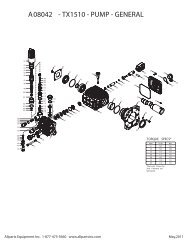
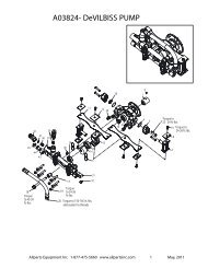
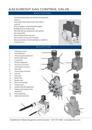
Illustrated Parts Diagram - Allparts Equipment & Accessories
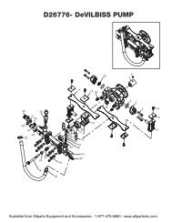
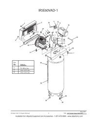
Illustrated Parts Diagram - Allparts Equipment & Accessories
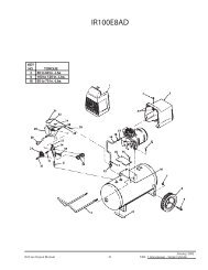
Illustrated Parts Diagram - Allparts Equipment & Accessories

Create successful ePaper yourself
Turn your PDF publications into a flip-book with our unique Google optimized e-Paper software.
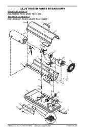
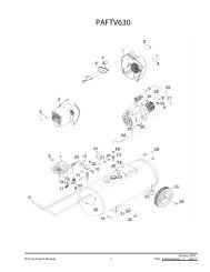
Pump Rotor(Procedure if rotor is binding)1. Remove upper shell (seepage 10).2. Remove filter end coverscrews using 5/16" nutdriver.3. Remove filter end coverand air filters.4. Remove pump platescrews using 5/16" nutdriver.5. Remove pump plate.6. Remove rotor, insert, andblades.7. Check for debris in pump.If debris is found, blowout with compressed air.8. Install insert and rotor.9. Check gap on rotor.Adjust to .076/.101 mm(.003"/.004") if needed(see Figure 27).Note: Rotate rotor onefull turn to insure the gap is.076/.101 mm (.003"/.004")at tightest position. Adjust ifneeded.10. Install blades, pumpplate, air filters, and filterend cover.11. Replace fan guard andupper shell.12. Adjust pump pressure(see page 14).Note: If rotor is still binding,proceed as follows.13. Perform steps 1 through 6above.14. Place fine grade sandpaper(600 grit) on flatsurface. Sand rotor lightlyin “figure 8” motion fourtimes (see Figure 28).15. Reinstall insert and rotor.16. Perform steps 10 through12 above.BladeFigure 25 - Rotor Location, 35/70,000 Btu/Hr ModelsInsertInsertRotorGap AdjustingScrewRotorAirOutputFilterFigure 26 - Rotor Location, 100/150,000 Btu/Hr ModelsGapAdjustingScrewFigure 27 - Gap AdjustingScrew LocationsBladeAir OutputFilterBladePumpPlatePumpPlateAirIntakeFilterFilter EndCoverAir IntakeFilterSandpaperFan Guard.076/.101 mm (.003"/.004") GapMeasured With Feeler GaugeRotorFilter EndCoverFan GuardFigure 28 - Sanding Rotor10268517