Illustrated Parts Diagram - Allparts Equipment & Accessories
Illustrated Parts Diagram - Allparts Equipment & Accessories
Illustrated Parts Diagram - Allparts Equipment & Accessories

You also want an ePaper? Increase the reach of your titles
YUMPU automatically turns print PDFs into web optimized ePapers that Google loves.
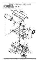
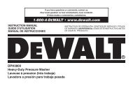
Nozzle(70/100/150,000 Btu/Hr Models)1. Remove upper shell (seepage 10).2. Remove fan (see page18).3. Remove fuel and air linehoses from burner head.4. Remove spark plug wirefrom spark plug.5. Remove spark plug fromburner head using 13/16"open-end wrench.6. Remove three screwsusing 5/16" nut-driverand remove burner headfrom combustion chamber.7. Place burner head intovise and lightly tighten.8. Carefully remove nozzlefrom burner head using5/8" socket wrench (seeFigure 24).9. Blow compressed air thruface of nozzle. This willfree any dirt in nozzlearea.10. Inspect nozzle seal fordamage.11. Replace nozzle intoburner head and tightenfirmly (9.1-12.4 n-m/80-110 inch-pounds).12. Attach burner head tocombustion chamber.13. Install spark plug inburner head.14. Attach spark plug wire tospark plug.15. Attach fuel and airlinehoses to burner head.16. Replace fan (see page18).17. Replace fan guard andupper shell.ScrewCombustionChamberAir Line HoseBurner HeadSparkPlugFigure 23 - Removing Burner Head, 70/100/150,000 Btu/Hr ModelsNozzleFaceNozzleBurnerHeadFuel Line HoseNozzleSealAir lineFittingSpark PlugWireFuel lineFittingFigure 24 - Removing Nozzle, 70/100/150,000 Btu/Hr Models16102685