Illustrated Parts Diagram - Allparts Equipment & Accessories
Illustrated Parts Diagram - Allparts Equipment & Accessories
Illustrated Parts Diagram - Allparts Equipment & Accessories

You also want an ePaper? Increase the reach of your titles
YUMPU automatically turns print PDFs into web optimized ePapers that Google loves.
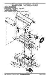
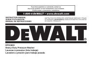
Nozzle(35,000 Btu/Hr Model)1. Remove upper shell (seepage 10).2. Remove fan (see page18).3. Remove fuel and air linehoses from nozzle assembly.4. Turn nozzle assembly 1/4turn to left and pulltoward motor to remove.5. Place plastic hex-bodyinto vise and lightlytighten.6. Carefully remove nozzlefrom the nozzle adapterusing 5/8" socket wrench.7. Blow compressed air thruface of nozzle. This willfree any dirt in nozzlearea.8. Inspect nozzle seal fordamage.9. Replace nozzle intonozzle adapter untilnozzle seats. Tighten 1/3turn more using 5/8"socket wrench (4.5-5.1n-m/40-45 inch-pounds).10. Attach nozzle assembly toburner strap.11. Attach fuel and airlinehoses to nozzle assembly.12. Replace fan (see page 18).13. Replace fan guard andupper shell.CombustionChamberAir Line HoseFuel Line HoseFigure 20 - Removing Air and Fuel Line Hoses, 35,000 Btu/Hr ModelBurnerStrapNozzleAssemblyNozzleAssemblyFigure 21 - Removing Nozzle Assembly, 35,000 Btu/Hr ModelNozzleFaceNozzleSealNozzleNozzleAdapterAir lineFittingFuel lineFitting102685Figure 22 - Nozzle and Nozzle Adapter, 35,000 Btu/Hr Model15