Illustrated Parts Diagram - Allparts Equipment & Accessories
Illustrated Parts Diagram - Allparts Equipment & Accessories
Illustrated Parts Diagram - Allparts Equipment & Accessories

Create successful ePaper yourself
Turn your PDF publications into a flip-book with our unique Google optimized e-Paper software.
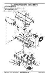
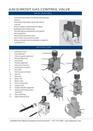
Air Output, Air Intake,and Lint Filters1. Remove upper shell (seepage 10).2. Remove filter end coverscrews using 5/16" nutdriver.3. Remove filter end cover.4. Replace air output and lintfilters.5. Wash or replace air intakefilter (see PreventativeMaintenance Schedule,page 8).6. Replace filter end cover.7. Replace fan guard andupper shell.IMPORTANT: Do not oilfiltersLint FilterAir OutputFilterAir Intake FilterFilter EndCoverFigure 16 - Air Output, Air Intake, and Lint Filters,35/70,000 Btu/Hr ModelsAir Intake FilterFilter EndCoverFan GuardFan GuardLint FilterAir OutputFilterFigure 17 - Air Output, Air Intake, and Lint Filters,100/150,000 Btu/Hr ModelsPump PressureAdjustment1. Remove pressure gaugeplug from filter end cover.2. Install accessory pressuregauge (part numberHA1180).3. Start heater (see Operation,page 7). Allow motorto reach full speed.4. Adjust pressure. Turnrelief valve to right toincrease pressure. Turnrelief valve to left todecrease pressure. Seespecifications at right forcorrect pressure for eachmodel.5. Remove pressure gauge.Replace pressure gaugeplug in filter end cover.14PressureGaugePlugFigure 18 - Pressure Gauge Plug RemovalPumpModel Pressure(PSI/Bar)35,000 Btu/Hr 2.9/0.2070,000 Btu/Hr 3.8/0.26100,000 Btu/Hr 3.9/0.27150,000 Btu/Hr 4.8/0.33(35/70,000 Btu/Hr Models Shown)ReliefValvePressureGaugeFigure 19 - Adjusting Pump Pressure102685