Marschalk 59000 Bladder Pump Controller - Geotech Environmental ...
Marschalk 59000 Bladder Pump Controller - Geotech Environmental ...
Marschalk 59000 Bladder Pump Controller - Geotech Environmental ...

You also want an ePaper? Increase the reach of your titles
YUMPU automatically turns print PDFs into web optimized ePapers that Google loves.
<strong>Marschalk</strong>Model #<strong>59000</strong> Low Submergence andModel #59500 Standard Submergence<strong>Pump</strong> <strong>Controller</strong>sInstallation and Operation ManualRev. 06/06/12 Part # 11150306
TABLE OF CONTENTSCHAPTER 1: SYSTEM DESCRIPTION................................................................ 4FUNCTION AND THEORY ....................................................................................... 4Features ........................................................................................................ 4SYSTEM COMPONENTS ........................................................................................ 6Background- .................................................................................................. 9CHAPTER 2: SYSTEM INSTALLATION ........................................................... 10EQUIPMENT SET-UP .......................................................................................... 10CHAPTER 3: SYSTEM OPERATION ................................................................ 11CONTROLLER SET-UP........................................................................................ 11SETTING CONTROLLER TIMERS .......................................................................... 11SETTING TIMERS WHEN IN “LOW SUBMERGENCE” MODE MODEL (<strong>59000</strong>) ONLY... 11SETTING PUMPING PRESSURE AT CONTROLLER ................................................. 14CHAPTER 4: SYSTEM MAINTENANCE............................................................ 16CHAPTER 5: SYSTEM TROUBLESHOOTING................................................. 18CHAPTER 6: SYSTEM SPECIFICATIONS ....................................................... 19CHAPTER 7: REPLACEMENT PARTS LIST..................................................... 20THE WARRANTY................................................................................................ 25EQUIPMENT RETURN POLICY ......................................................................... 25EQUIPMENT DECONTAMINATION................................................................... 251
DOCUMENTATION CONVENTIONSThis manual uses the following conventions to present information:WARNINGAn exclamation point icon indicates aWARNING of a situation or condition that couldlead to personal injury or death. You should notproceed until you read and thoroughlyunderstand the WARNING message.CAUTIONA raised hand icon indicates CAUTIONinformation that relates to a situation or conditionthat could lead to equipment malfunction ordamage. You should not proceed until you readand thoroughly understand the CAUTIONNOTEA note icon indicates NOTE information. Notesprovide additional or supplementary informationabout an activity or concept.2
This manual covers operation and maintenance of both the Model <strong>59000</strong> Low Submergence and Model59500 Standard Submergence pump controllers.Please read the entire manual prior to using the unit, as it contains information which can help youenjoy years of low maintenance use of not only the pump controller, but System 1 pump andcompressor units as well.3
Chapter 1: System DescriptionFunction and TheoryThe controller is an integral part of the <strong>Marschalk</strong> Low Flow dedicated and portable well samplingsystems. It can also be used with virtually any other bladder pump system available. It performs severalfunctions necessary for the efficient operation of any of the System 1 bladder and gas displacementpumps. System 1 pump controllers are designed to enable the operator to match the performancecharacteristics of System 1, as well as other gas displacement type pumps to the unique requirementsof each sampling application. For purging or sampling, the operator can easily vary the pump flow ratesfrom purging to sampling, with consistent, uniform flow rates down to ≤ mls/min. Once the controllerhas been setup for a particular well, operation is completely automatic. The <strong>59000</strong> Series controller is aLow Submergence model. In addition to two cycle operation normally found on other controllers, the<strong>59000</strong> offers a third enhanced fill cycle which provides an overall system versatility that is unmatchedby others. The Model 59500 <strong>Controller</strong> is a Standard Submergence 2 Cycle model of the series.FeaturesAutomatic OperationEasy set-up and operation with digital timers (one timer only on 59500)Weatherized Construction, with 0-ring seal for protection in adverse environments.All connections for air lines and power are located on the outside of the enclosure to enable operationwith the cover closed.Solid State Timers provide an unmatched degree of precision and accuracy for setting and maintainingcycle times, whether in seconds, minutes, or hours. Low Power Consumption.In addition to the use of the highest quality components, controllers have been extensively field testedfor over 20 years in hundreds of applications worldwide, assuring you of dependable performance andreliability.4
The major differences between the model <strong>59000</strong> and 59500 are;<strong>59000</strong>Provides Low Submergence pumping capability with a System 1 or other bladder or gas displacementpump. Low Submergence pumping enables the user to pump low yield wells to within a few inches ofthe bottom of the well; fill the pump faster where static water level is at or near the top of the pump;pump from the upper few inches of the water column; to connect a skimmer to the intake of the pump topump product from the surface; and to pump from a small bucket at the surface to facilitate cleaning ofthe pump.59500Includes all capabilities of the <strong>59000</strong>, with the exception of those where Low Submergence would berequired. With the 59500, static water level must be 3 ft. or more above the intake (bottom) of thepump, and remain at this level during pumping. The 59500 can easily be upgraded to a <strong>59000</strong>.5
System ComponentsCompound Gauge - 30“ Hg to 160 psi, liquid filledPressure Regulator - 10 psi to 130 psi - regulator is used to set pumping pressure during pump cycle,and to adjust pump flow rate. Lock ring -down to lock regulator knob, up to unlock and adjust pressure.Turn knob clockwise to increase pressure & flow rate, and counter-clockwise to decrease pressure &flow rateSolid State Cycle Timers (2 on <strong>59000</strong>; 1 on 59500). Timer 1 (T1) on left controls pump on time and off,or fill, time; Timer 2 (T2) on right controls enhanced fill time when unit is operated in Low Submergencemode.Power On/Off Selector Switch - On to the right powers unit on for 2 cycle, standard submergenceoperation; On to the left powers unit on for 3 cycle, Low Submergence operation. On 59500 unitoperates with power switch on to standard submergence only.6
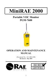
Vent/Silencer- right side lower rearAir In from compressor/cylinder- right side forward top -brass male quick-connect plugAir out to pump - right side forward lower-brass lemale quick-connect couplerRig.h1 Side Fittings • OOth modelsAir In fromCompressor7
TIMER ILLUSTRATIONOFF Indicator (Green) - On when power is applied to controller, & during pump “Fill” cycle.When in Standard Submergence, T1 green light only will illuminateWhen in Low Submergence, T1 and T2 green lights will illuminateON Indicator (Orange) - On during “<strong>Pump</strong>” CycleON indicator lamp on T2 (<strong>59000</strong> model only) will illuminate during enhanced fill cycle in LowSubmergence operating mode.Rated Time Selector - use to change scale of numerals on face of timer,(0 to 1.2; 0 to 3; 0 to 12; and 0to 30)ON Time units selector - Use small phillips head screwdriver to change time units to seconds, minutes,or hours. Selected units appear in window above the screw.Setting Dial for OFF (vent/fill) - green pointerSetting Dial for ON (<strong>Pump</strong> time for T1/Enhanced Fill time for T2 in Low Submergence mode(Model<strong>59000</strong>)OFF Time unit selector - Use small phillips head screwdriver to change time units to seconds, minutes,or hours. Selected units appear in window above the screw.8
Background-Low Flow, Low Stress Purging and SamplingConceptThe Low Flow purge and sample method for ground water monitoring is the result of many years ofdevelopment, part of which has been undertaken by U.S. EPA. Because of the numerous advantagesLow Flow offers over older, higher rate pumping methods, it has quickly become a standard forcollecting high quality representative ground water samples. Low Flow procedures require pumping in amanner which minimizes stress, or water level drawdown, i.e. low-impact pumping. This is bestachieved with dedicated sampling devices installed within the screened interval, and capable ofproducing continuous, uniform low flow rates on the order of 100 to 500 mls/min. for both purging andsample collection. The prescribed flow rates must be achieved ideally without creating any turbulencein the well, particularly at the sampling point. Primary objectives of this method are to 1) pump at a ratesufficiently low to ensure collection of samples which flow naturally across the screened interval, whileminimizing or eliminating sampling induced turbidity associated with pump operation, 2) minimize oreliminate movement of the pump during pumping, The bladder pump has proven to be an ideal choicefor accomplishing all of the objectives of the Low Flow method.GeneralAlthough similar in operation to a standard System 1 dedicated well purge and sample system,operation of the Low Flow system varies slightly due to the need to purge at a relatively low, uniformrate of 100-500 mls/min.Method OverviewOne of the many advantages to the use of the Low Flow method is, if you’ve been using a System 1bladder pump in the past, you do not have to replace your existing equipment. Although shorter pumpsand smaller diameter tubing may be specified for new sites, higher volume pumps and tubing whichmay be installed at older sites can easily be used by merely changing the sampling method. Purgevolumes and time may increase slightly, however these systems can still easily meet the objectives ofthe Low Flow method. To take full advantage of the many areas of savings associated with the method,and to ensure that the best quality samples are collected on a consistent basis, dedicated bladderpumps are preferred.With the use of the Low Flow method, purge volumes are significantly reduced from older multiple wellvolume purging methods. Because the stagnant water found in a monitoring well is normally not afactor in a Low Flow application, the purge volume theoretically becomes the volume of water held inthe bladder element of the pump and in the total length of the discharge tubing. When using the LowFlow method, if you are pumping at a rate which is usually considerably less than the recharge rate ofthe well, you will be drawing water into the pump from the aquifer through the well screen, rather thanfrom the water column above or below the pump intake. If water in an aquifer flows horizontally,normally a given, and you pump at a rate which is less than the rate of water entering the well casingfrom the aquifer, the pump intake will see only that water which is moving across the screen,horizontally, from the aquifer. This being true, the only water volume which is considered stagnantwhen pumping begins, is the water that is theoretically held, or trapped, in the pump bladder and thedischarge tubing from the previous sampling event. Water contained in the annular area between thepump intake and the wall of the screen itself may also be considered stagnant. In a typical 2“ diameterwell casing, the volume within this annular area is quite small. In practice it may take purging one tothree or even more of these theoretical volumes before field analytes stabilize and you can collect asample.To meet the objectives of the Low Flow method as noted above, there are a few modifications whichneed to be made with respect to how the equipment is setup and operated.For Low Flow, consideration should also be given to the rate at which the pump refills on the vent, or fillcycle. Ideally, this rate should be as low as possible to ensure that water is entering the pump at a lowvelocity.9
Chapter 2: System InstallationEquipment Set-UpPlug the filter end of the RED air supply hose into the “Air In” port on the right side of the controller. Theother end of this hose connects to the air supply, which is typically an oil-less air compressor or an airor nitrogen cylinder.Plug in the male quick-connect plug end of the YELLOW controller discharge hose to the female quickconnectcoupler marked “Air Out” on the side of the controller. The other end of this hose connectsdirectly to the pump air tubing via a push-type quick connector, or to the brass male quick-connectpump air supply fitting on the wellhead assembly for a dedicated system.Plug the cigarette lighter male plug end of the coiled controller power cord into the 12 volt dc powerpack, or into a vehicle cigarette lighter receptacle. Any 12 volt dc power supply having a capacity of 4amp-hours or higher will adequately power the controller. Plug the other end, 5 pin amphenol plug, intothe power receptacle on the left side of the controller.Start the air compressor and allow it build up to set pressure. At this point the valve on the compressorair tank should be closed. The valve can be opened after set pressure has been reached and air hoseshave been connected to the compressor and controller.NOTE: During operation of the controller, compressed air supply at the inlet of the controllermust be maintained at 40 psi minimum to ensure continuous operation of the controller.NOTE: 12 V dc power source must be fully charged. If not, timer lamps will illuminate, but thesolenoid will not function.10
Chapter 3: System Operation<strong>Controller</strong> Set-UpPull up the yellow lock-ring on the pressure regulator located in the lower left corner of the controllerpanel, and turn the regulator knob counter-clockwise until it turns loosely. This will set pumpingpressure to a minimum.NOTE: Adjustment of the pressure regulator to a minimum pressure setting should be donefollowing sampling of every well to ensure that minimal pressure is applied initially to the pump in eachsubsequent well to be sampled.Setting <strong>Controller</strong> TimersFor the purpose of this discussion, assume that you will be using the Standard Submergence “On’setting on the controller. When using the Low Flow method, it is best to use this setting wheneverpossible. For Standard Submergence, two cycle operation, the controller is powered on by turning theselector switch “On” to the right. For Standard Submergence, and for the 59500 controller, only the lefttimer, T1 is used. Please refer to the timer illustration on page 6 for details of the timer. The timer has 2dials. The smaller center knob controls the dial which has an Orange pointer, while the larger outer dialhas an Green indicator line on it. “T.on” controls the pump time. This is the time that pressure is appliedto the pump to effect pumping. When the power switch is turned on, a green indicator lamp illuminates,indicating that the timer is now energized. The first cycle the timer enters is the “T.off”, or fill, cycle.During subsequent fill cycles, pressurized pumping air will be vented out the vent port on the right sideof the controller. Once pressure has been vented to atmosphere during the fill cycle, the pump bladderbegins to fill. This cycle will last as long a time as is indicated by the Green pointer. Immediatelyfollowing the time-out of the fill cycle, the pump cycle will begin. At the start of the actual pumping cycle,an orange indicator lamp will illuminate, and this cycle’s duration will be as long as indicated by theOrange pointer. The timer increments and units can easily be changed as indicated on the illustrationon page 6. The timer’s dial face settings can be changed using a small phillips head screwdriver from0-1.2, 0-3, 0-12, and 0-30.The default dial face is set to 0-1.2. In most cases, for Low flow sampling,you will be operating the timer at either sec., 10 sec., or minutes.Setting Timers When In “Low Submergence” Mode Model (<strong>59000</strong>) OnlyWhen the controller is operating in the Low Submergence, or 3 cycle mode, green power lamps on bothtimers, T1 & T2 will illuminate. The “<strong>Pump</strong>” knob (Orange indicator line) of T1 controls the duration ofthe pump or pressurization cycle. In this mode of operation, the “Fill” knob (Green indicator line)controls the entire duration that T2 operates. The “Fill” knob of T1 (Green Line) should be set greaterthan or equal to the sum of the “Enhanced Fill” and “Vent” times set on T2. For example, if it is determinedthat the “<strong>Pump</strong>” cycle (T1) should be 0.1 minute, or 6 seconds, and the “Enhanced Fill” time (T2)should also be 0.1 minute, the actual timer settings are as follows. The “<strong>Pump</strong>” (T1) time is set to 0.1.The “Vent” cycle of T1 is set to 0.2 (12 sec.), the “Enhanced Fill” time on T2 is set to 0.1 (6 sec.) withthe Orange indicator line, and T2‘s vent time, the Green indicator line is set to “0.1”. With the Vent timeon T1 set to 0.2, both indicator lines on T2 could also be set to 0.05 min. each. This setting wouldprovide a different time for the “Enhanced Fill” cycle-only 0.05 min, or 3 seconds. It would also providethe same amount of time, 0.05 min. for the vent cycle of T2. The vent cycle of T2 is used to vent, orbleed off the pressurized air created during the pump cycle and begins following the pressure cycle onT1 (orange line). If the Fill setting on T1 is set greater than the sum of both settings on T2, there is asecond Vent cycle that begins after the Vacuum cycle. This vent bleeds the vacuum prior to pumping.Minimize this time to increase flow rates.11
When the “Enhanced Fill” cycle activates, the red lamp on T2 will illuminate, just as the red lamp on T1illuminates during a pump cycle. Also, during the Enhanced Fill cycle, the needle on the controllerpressure gauge will drop beyond “0” and into the vacuum range of the gauge until It reaches amaximum vacuum of approximately 15“ Hg. This is the equivalent of about 15 feet of water. It should benoted that there is no vacuum imposed on the sample during this cycle, as the vacuum merely makesthe pump behave like it has up to 15 feet of water above the intake.Always set the “Enhanced Fill” cycle time as short as possible, as the cycle uses a considerableamount of compressed air to create a vacuum. As with the pump and fill cycles, the enhanced fill cycletime is dependent on the depth of the pump intake. As a guide, set the enhanced fill time at first toabout 6 seconds, or 0.1 min. When the Enhanced Fill cycle begins, watch the pressure gauge. After theneedle reaches the maximum vacuum point of about 15“ Hg, wait about 3-5 seconds. At this point thecontroller should switch to the pump cycle, i.e. the Enhanced Fill cycle should stop (red indicator lampon T2 will go off). If it takes more than 3-5 seconds for cycles to switch, shorten the Enhanced Fill cycle.NOTE: If you are trying to pump at a high flow rate, for multiple well volume purging for example,your objective will be to keep all cycle times as short as possible. In this case Enhanced Fill should onlybe used where it offers a flow advantage, such as for enabling the pump to be filled faster. Rememberthat there is a trade-off however with Enhanced Fill. It may fill the pump faster, but it also takes up time.For maximum efficiency, use the following as a guide in setting cycle times. When using 2 cycle modeof operation (T1 only), adjust the pump cycle time to switch off as soon as the discharge of water stops.But only if a full volume of water has been discharged. If less than a full volume of water has beendischarged, the fill time may have to be increased to ensure that the pump has filled completely. Oncethe optimum cycle times and pressures have been established for a well, log in these settings on a welllog sheet. Then next sampling event you won’t have to set up the controller again.Timer Set-Up ExampleIn order to set the timer cycles properly, you need to know the following, considered constants:A PTFE bladder on a 24“ Aquarius II pump holds about 250-300 mls.of water.0.250” discharge tubing, typically used with Low Flow, holds about 9.7 mls/ft of water.NOTE: For various reasons, including minimizing wear on the bladder element, and to ensureuniform flow rate, it is best for Low Flow sampling to empty only 100-170 mls of water per pump cycle.Let’s assume you have a 32ft. 2“ diameter well, with the pump intake at 30 ft., and you wish to pump100 mls/min. To pump 100 mls/min., the pump cycle time should be set for 1 minute. If you wanted topump 200 mls/min. set the pump cycle time (Orange indicator, “T.on” to 30 seconds (0.5 mins. on thedial). 100 mls should be discharged during each pump cycle, and flow should be observed over theentire 30 second pump cycle. If 100 mls is discharged over less than the 30 second pump cycle, reducethe controller pumping pressure, as this will reduce the flow rate.The Vent, or Fill, time set by the Green indicator, will vary as a function of several factors. <strong>Pump</strong> intakedepth and height of the water column above the pump intake are two important variables for properlysetting the pump fill time. For Low Flow sampling, the pump should fill slowly. Ideally, the pump intakeshould be submerged in the water column by less than 10 ft. submergence can be reduced ifnecessary, through the use of a drop tube pump configuration, or through the use of the Series 6000Auto <strong>Controller</strong>, as the computer in the Auto <strong>Controller</strong> will automatically control the rate at which thepump fills, regardless of the height of water above the pump intake. As a guide, when the fill cyclebegins, wait for the set pumping pressure to reach “0”, then wait another 3-5 seconds, then set the filltime to end and switch to the pump cycle. If you can not consistently obtain a 100 mls, or 150 mls,whatever your target volume is for a pump cycle, during a pump cycle, try increasing the fill time untilyou do.12
IMPORTANT : When you first begin pumping, it is very important to apply pressure in smallincrements, until water is observed at the surface. Start out with a pumping pressure of 3-5 psi,regardless of what your calculated final pressure should be, and at the beginning of each subsequentpump cycle, increase the pressure by an additional 3-5 psi until water flow at the surface is observed.This is important to maintain the integrity of the PTFE bladder element in the pump. If you follow thisrule, the bladder can last for 10 years or more.DISCHARGING TO SAMPLE BOTTLES AND FLOW-THROUGH CELLSIn order to achieve consistent, uniform flows at the surface, the following recommendations are offered:System 1 discharge tubing leads are typically 1/8“ i.d. tubing, regardless of material, and about 30” inlength. When pumping at rates of less than about 150 mls/min., a smaller diameter extension, or areducing barbed nipple should be used. A chemical resistant, Kynar nipple is available for this purpose.The barb simply slips inside of the 1/8“ tubing lead, and provides considerably more control for lowerflow rates. This restricting device also minimizes the chance for air to get into the discharge tubing, andthe sample, during the fill cycle.When measuring flow rates, the end of the discharge tubing should be held up at an angle so the actualpoint of discharge is higher than the well. This will prevent water from simply falling out of the tubing.When connecting the discharge tubing to a flow cell that is full of water, this is not necessary.The use of a “sampling tee” between the sample discharge tubing and the flow cell is recommended, ifused. Through valving included on the tee, the water flow through the sample discharge tube can beeasily diverted directly to a sample bottle when field analytes have stabilized.13
Setting <strong>Pump</strong>ing Pressure At <strong>Controller</strong>IMPORTANT: Always start pumping with controller pressure set at 3-5 psi as indicated onthe controller pressure gauge. During each subsequent pumping cycle, increase controller (pumping)pressure by an additional 3-5 psi until water is observed at the surface. Then you can adjust to youroptimum final pressure.Air inFormula for estimating pumping pressur e :P = D/2 -SWLt/2 + 5 *, whereP = Pressure, in PSI, as set with pressur eregulator on controller panel.D = <strong>Pump</strong> Depth, in feet, measured from t hetop of the well to the bottom (intake) of th epump.SWLt = Distance, in feet, from the top of t hewell casing to the top of the water colum nIN THE PUMP DISCHARGE TUBING(Not the Well Casing)Note: that this value will change (decrea se )with every pump cycle until water is obser vedat the surface.Water Level In<strong>Pump</strong>DischargeTubing*The value of “5” in the formula will likely besmaller, and closer to the theoretical pre ssu r e r equ ir ed t o e ff ec t fl ow f o rLow Flow purging and sampling.With the use of the series 6000 Auto Co n tr o ll e r, pump i ng p r essu r e i s se t au tomatically by the internalcomputer.Please refer to the example provided on the following page for using the above formula to calculate thecorrect pumping pressure, as set on the controller, for any given well.14
Setting <strong>Controller</strong> Pressure - ExampleP = D/2 -SWLt/2 + 5FOR THIS EXAMPLE:Air inD = 50 ft. & SWLt = 40 ft.Note: In this example, thein the well and pumping has notSWL, the water level in the welltop of the well to the top of theTo set the initial pumpingabove:pump has just been installedyet begun. At first, SWLt=casing, as measured from thewater column.pressure, using the formulaP= D/2 - SWLt/2 + 5P = (50/2) - (40/2) + 5P= 25 - 20 + 5P = 10 psigWater Level In<strong>Pump</strong> DischargeTubingTo set this pressure at thelocking ring on the pressureadjustment knob. Turn regulatorturns loosely. This will setWhen the pump cycle begins,clockwise until the pumpingreached. As you turn thepressure will be evident on thecontroller panel. Please note thatincreases/decreases on thecycle.controller, FIRST pull yellowregulator up to unlock theknob counter-clockwise until itpressure at essentially “0” psi.turn the regulator knobpressure calculated above isregulator knob, the increase inpressure gauge on theyou can only see pressuregauge during the “<strong>Pump</strong>”Now, as the pump operates and water rises in the pump discharge tubing, SWLt will decrease. AsSWLt decreases, you can see from the formula above that “P” will increase. Every time a pump cycle iscompleted pressure must be increased in small increments at the controller until the maximum requiredpumping pressure is reached. At this point water will be coming out of the discharge tube at thesurface. The recommended interval to increase the pumping pressure with each pumping cycle is 3-5psi, until flow is observed at the surface.IMPORTANT: Adjust the pumping pressure as described above in order to prevent excessive pumpingpressures, which can over-collapse a PTFE bladder element, reducing its operating life, and making itdifficult to achieve the objectives of low flow sampling.If the pumping pressure is set in the recommended manner, PTFE bladder elements will last forseveral years - so far, 15 years and still going!15
Chapter 4: System MaintenanceIMPORTANT: To ensure continuous satisfactory operation of the pump controller, we recommend thatyou adhere to the following recommendationsKeep air hose ends off the ground and out of the dirt. To keep internal surfaces and quick-connect endsof hoses free of loose dirt, prior to beginning pumpingStart compressor and allow air pressure to build up in tank -discharge valve should be closed duringpressure ramp up.Connect air hoses, one at a time, to the discharge fitting on the air compressor. The other end shouldbe open to atmosphere -and pointed away from personnel.After pressure has built up in tank, open tank valve and blow out hoses.Keep air storage tank on compressor drained of condensate. Start draining at a rate of once per hour,then adjust as necessary. All System 1 compressors include a drain petcock on the bottom of the tank.Where shallow wells are being sampled, it may be possible to operate the compressor with the petcockcracked open to keep the tank drained.Install a combination filter and water separator at the discharge point of the air compressor. This willminimize the possibility of condensate water and particulate matter from the air tank from going throughthe pump controller and possibly fouling controller valving. No. 91250 Red air supply hoses are providedwith an in-line particulate filter on the controller end of the hose.<strong>Controller</strong> will not operate consistently when ambient temperatures dips below about 32°F. Whensampling at lower temperatures try to operate the controller inside a heated vehicle.Make certain the Power Supply for the controller is fully charged and is outputting 11.5 volts dc orhigher. At voltage values less than this, the controller timer lamps may illuminate, but power may not beadequate to shift internal valves that require 12 volt dc power. When the power supply is fully charged,it should operate the controller for over 20 hours before it requires recharging. Ambient temperatureslower than freezing, as well as the age of the power supply, i.e. the number of times it has beenrecharged, will affect the overall performance of the power supply. At the time the power supplyappears to recharge properly, but does not last more than an hour or two, it is time to replace it. Thecontroller can be operated from virtually any 12 volt dc power supply, including a vehicle battery,through the cigarette lighter receptacle. Replacement power supplies are available however, if you arestuck in the middle of a sampling event many different retail stores should have them; Wal-Mart, Target,auto supply stores, Sears, etc.NOTE: Pressure at the discharge point of the air compressor must be maintained at a minimumof 40 psi, as read on the compressor gauge, to ensure satisfactory and consistent operation of thecontroller.After each day of use with an air compressor as an air supply, purge the controller with clean, dry air.Turn off the compressor and let it cool down. Drain the tank.Disconnect the controller/wellhead air hose (yellow) from controller.Restart the compressor and build up pressure in the tank. open drain petcock slightly.16
Remove controller air silencer from the controller “Vent” port on the right side of the unit. The silencershould be hand-tight only, so removal should be easy.Run controller for a few cycles, in 3 cycle mode if you are using a Model <strong>59000</strong>, to purge out any dirtand/or moisture.It is recommended that, if you do not already use one, have your field technicians maintain a log sheet,and keep it with the controller. This is something that would best be completed on a daily basis. Alongwith controller Serial Number, include any problems encountered and any field maintenance performed.Include a check box for completion of end of day purging of the controller, and a signature line.17
Chapter 5: System TroubleshootingIf low pump output is being encountered it may be due to the 12V lighter receptacles or plugs. Makecertain these connections are fully plugged in. Once fully plugged in, rotating the connection can help ifthere is a dead spot in the connector. Also, normal wear and tear on cables, receptacles and plugscould cause undesired operations. Check for fatigue, cracks, rust etc.If you do require factory service, if it is at all possible, please have the person who experienced theproblem while using it call our service department, as this will make it easier to diagnose the problem.Call toll free at 1(800) 833-795818
Chapter 6: System SpecificationsBoth the <strong>59000</strong> and 59500 are housed in a field-tough polyethylene case. Both operate from anexternal 12 volt dc power supply and compressed air or nitrogen. Dimensions for both units are 10.6” x9.8” x 7”. Weight is 7 lbs. for the <strong>59000</strong> and 6 lbs. for the 59500.Consistent, uniform flow rates to < 25 mls/min. with System1 bladder pumps forLow Flow Sampling.<strong>Pump</strong> low yield wells to within 2”-3” of the bottom (Model <strong>59000</strong>).19
Chapter 7: Replacement Parts ListRegulator,Air, 10-13011150275PSIGauge,160PSI,LF,1/4"MPT11150276(59500)Gauge,30”HG 0-150PSI,LF,111150310/4”MPTSwitch, 311150280PositionSwitch,Oper, 311150281Pos, <strong>59000</strong>Solenoid,Valve,12VDC11150282<strong>59000</strong>Elbow,Legris,5/32Pushx1/111502848MPTElbow,Legris,5/32x1/411150285FPTReducer,Legris,5/32Pushx1/111502864TubeAmp. Conn.,Pwr DCPanel17200014MountTubing, Nyl,1/4ODx0.03166000075W, BlkTubing, Nyl,.106"X.156",Yellow/Gree11150291nQck Cnct,Brs,172003511/4x1/8MPTQck Cnct,Brs,1/4Mx1/8FP17200277TMuffler, 1/8"11150294MPT,<strong>59000</strong>Power Cord,57500008DC11150300 Ejector Vac.20
1115030111150302111503031115030411150306108601/8 MPT 1/4Air PilotSingle 1/8NPTElbow,Legris,1/4Pushx1/8MPTTee,Legris,1/4x1/4PushpullxTubeReducer,Legris,1/4Pushpullx 5/16TubeManual,<strong>Marschalk</strong><strong>59000</strong>Eight Pin,Timer Relay21
Notes22
Notes23
Notes24
The WarrantyFor a period of one (1) year from date of first sale, product is warranted to be free from defects in materials andworkmanship. <strong>Geotech</strong> agrees to repair or replace, at <strong>Geotech</strong>’s option, the portion proving defective, or at our optionto refund the purchase price thereof. <strong>Geotech</strong> will have no warranty obligation if the product is subjected to abnormaloperating conditions, accident, abuse, misuse, unauthorized modification, alteration, repair, or replacement of wearparts. User assumes all other risk, if any, including the risk of injury, loss, or damage, direct or consequential, arisingout of the use, misuse, or inability to use this product. User agrees to use, maintain and install product in accordancewith recommendations and instructions. User is responsible for transportation charges connected to the repair orreplacement of product under this warranty.Equipment Return PolicyA Return Material Authorization number (RMA #) is required prior to return of any equipment to ourfacilities, please call 800 number for appropriate location. An RMA # will be issued upon receipt of yourrequest to return equipment, which should include reasons for the return. Your return shipment to usmust have this RMA # clearly marked on the outside of the package. Proof of date of purchase isrequired for processing of all warranty requests.This policy applies to both equipment sales and repair orders.FOR A RETURN MATERIAL AUTHORIZATION, PLEASE CALL OURSERVICE DEPARTMENT AT 1-800-833-7958 OR 1-800-275-5325.Model Number:Serial Number:Date:Equipment DecontaminationPrior to return, all equipment must be thoroughly cleaned and decontaminated. Please make note onRMA form, the use of equipment, contaminants equipment was exposed to, and decontaminationsolutions/methods used.<strong>Geotech</strong> reserves the right to refuse any equipment not properly decontaminated. <strong>Geotech</strong> may alsochoose to decontaminate equipment for a fee, which will be applied to the repair order invoice.25
<strong>Geotech</strong> <strong>Environmental</strong> Equipment, Inc2650 East 40 th Avenue Denver, Colorado 80205 (303)320-4764 ● (800) 833-7958 ● FAX (303) 322-7242email: sales@geotechenv.com website: www.geotechenv.com