Protector Trip Relays - Crompton Instruments
Protector Trip Relays - Crompton Instruments
Protector Trip Relays - Crompton Instruments

You also want an ePaper? Increase the reach of your titles
YUMPU automatically turns print PDFs into web optimized ePapers that Google loves.
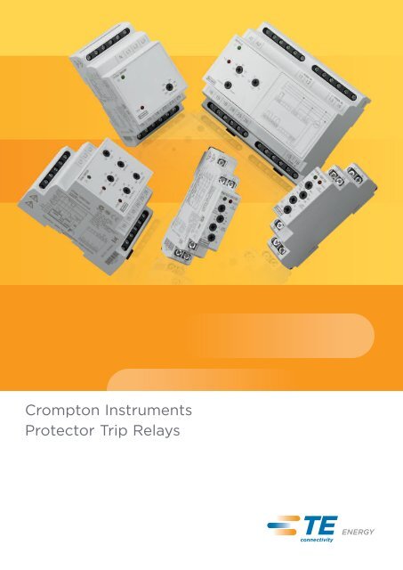
<strong>Crompton</strong> <strong>Instruments</strong><strong>Protector</strong> <strong>Trip</strong> <strong>Relays</strong>
<strong>Protector</strong> <strong>Trip</strong> <strong>Relays</strong>An extensive range of electronic control products providingcontinuous monitoring and protection of any electrical parameter.When the monitored parameter deviates from the desired set triplimit, the relay will operate to prevent damage to power asset.This versatile range features a host of stylish DIN-rail protectorsoffering numerous trip functions for single and three-phase powersystems, including over and under voltage, current, frequency,phase sequence/failure or balance, reverse power, synchro-check,speed sensing and finally DC inputs.ContentsPageAC Current 2 - 5AC Voltage 6 - 11Frequency 12 - 13Phase Sequence and Phase Failure 14 - 15Phase Balance, Sequence and 16 - 17Voltage MonitorSynchro-check (Paralleling) 18 - 19Features• LED fault indication• Adjustable nominal voltages, trippoints, time delay and differentials• Compact DIN-rail enclosure• Power on LED (Green)• Designed to avoid nuisance trippingBenefits• Protection of power assets• Detection and isolation of faults• Maintains supply continuity ofhealthy circuits• High speed tripping to avoiddamageApplication• Switchgear• Distribution systems• Process control• Motor protection• Equipment and network protectionReverse Power (Current) 20 - 21DC Millivolts and Transducer 22 - 23Thermistor 24 - 25Speed Sensing 26 - 27373-ELR Earth LeakageProtection Relay 28 - 29CBT-94F Core Balanced 30Current Transformers373-GFR Ground Fault Relay 31 - 32Part Numbers 331
AC CurrentAC current protectors provide a continuous surveillance ofmonitored circuits and offer user adjustable trip points (set points)with time delay settings. When the current moves outside the setpoint limit for longer than the time delay, the relay will operateproviding an alarm control or tripping signal.Basic Parameters• Universal auxiliary supply 24-240V AC/DC galvanically isolated from monitoredcurrent circuit• Pre-set differential (hysteresis) 1%• <strong>Trip</strong> level adjustment between 40-120% (In)• Available with 1A or 5A nominal inputs of (In)• Power on LED (green)Under Current - PAU• Single-phase• Continuously monitors to provide under current protection (set level Imin)• Adjustable time delay• 1 module versionOver Current - PAO• Single-phase• Continuously monitors to provide over current protection (set level Imax)• Adjustable time delay• 1 module versionUnder and Over Current - PAD• Single-phase• Monitors decrease of current under a set level Imin and simultaneously an overrange of current above a set level Imax• Independently adjustable delay on both over and under set points• Two output relays• Three module versionUnder or Over Current - PAP/V• Three-phase, three/four-wire• Continuously monitors to provide under or over protection (set level In)• Monitors three-phase current• Selectable under or over protection• Six module versionPart no. 1-phase 3-phase 3/4-wire ProtectionPAU x Under currentPAO x Over currentPAD x Under and over currentPAP/V x Under or over current2
AC CurrentOperationThe set point adjustment range is between 40% and 120% of thenominal current with 1A or 5A nominal input current (via currenttransformers or direct connection). An internal differentialsetting of 1% reduces nuisance tripping if the measured signal isnoisy or unstable. Relay will trip if the measured current movesoutside the set point limit and the red LED indicates a faultcondition. An adjustable time delay eliminates prematureoperation on short duration current fluctuations. During thisdelay period the red LED will flash. <strong>Protector</strong>s draw theiroperating power from a separate auxiliary supply input.Under Current - PAUShould the monitored current fall below the set point levelImin, the protector will trip and the red LED will illuminateindicating the fault condition. During the time delay period thered LED will flash for the set time (t) before the relay deenergisesoutput relay contacts. The relay will automaticallyreset once the monitored current rises above the set point levelImin plus the differential (internally pre-set 1%) causing the redLED to extinguish and the relay to make without time delay.Over Current - PAOShould the monitored current exceed the set point level Imax,the protector will trip and the red LED will illuminate indicatingthe fault condition. During the time delay period the red LEDwill flash for the set time (t) before the relay energises outputrelay contacts. The protector will automatically reset once themonitored current falls below the set point level Imax plus thedifferential (internally pre-set 1%) causing the red LED toextinguish and the relay to release without time delay.Under and Over Current - PAD- PAD is a combination of both PAU and PAO products.Under or Over Current - PAP/VThe manner of operation depends on the mode selected at thefront panel either Under Current or Over Current.Note: Red LED indicates fault condition, not relay status.CharacteristicsPAUPAOPADPAP/V<strong>Protector</strong> OverviewPAU, PAOPAP/VPAD3
AC CurrentSingle-phaseTechnical parameters PAU-1 PAU-5 PAO-1 PAO-5 PAD-1 PAD-5• •Under current protection (de-energise on trip)Over current protection (energise on trip)Auxiliary supply terminalsA1, A2Auxiliary supply voltage24-240V AC/DCAuxiliary supply voltage tolerance ±10%• •• •• •Auxiliary voltage burden (max) 2.6VA/0.8W 3VA/1.2WOperating frequency AC45-65 HzCurrent input terminalsI1, I2Rated current In 1A AC 5A AC 1A AC 5A AC 1A AC 5A ACCurrent input burden (max) 0.1VA 0.5VA 0.1VA 0.5VA 0.1VA 0.5VAUpper current limit ImaxAdjustable 40-120% lnLower current limit IminAdjustable 40-120% InOverload capacity-continuos 2A 10A 2A 10A 2A 10A-max. 3s 20A 50A 20A 50A 20A 50ADifferential (hysteresis)Internally pre-set at 1% InTime delay Adjustable 0.5-10s Independently adjustableunder/over 0.5-10sOutput relay-contact 1x change over (AgNi) plated 2x change over (AgNi)platedOutput relay-contact 15, 16, 18 Under 15, 16, 18/overterminals 25, 26, 28Load capability of relay contact AC250V/8A, max. 2000VALoad capability of relay contact DC30V/8AMechanical life3x10 6 by rated loadRelay resetAutomaticANSI no. 37 37 50 50 37/50 37/50Operating temperature-20 +55°CStorage temperature-30 +70°CElectric strength (supplying - contact relay)4kV/1min.Overvoltage categoryIII.Pollution degree 2Enclosure integrity IP40 from the front panel IP40 from the front panel/IP10 terminals/IP20 terminalsEnclosure style DIN-rail, 1 module DIN-rail, 3 moduleCase materialFlame retardant polycarbonateConnecting conductors profile (mm 2 ) max. 2x2.5mm 2 /1x4mm 2 max. 2x1.5mm 2 /1x2.5mm 2Dimensions H90xW17.6xD64mm H90xW52xD65mmWeight 70g 70g 70g 70g 208g 208gStandards EN 60255-6, EN 60255-27, EN 61000-6-2, EN 6100-6-4ConnectionPAU, PAOPAD4
AC CurrentThree-phase three/four-wireTechnical parameters PAP/V-1 PAP/V-5Under current protection (de-energise on trip) Selectable SelectableOver current protection (energise on trip) Selectable SelectableSystem type 3-phase (3~) 3-phase (3~)Auxiliary supply terminalsA1, A2Auxiliary supply voltage24-240V AC/DCAuxiliary supply voltage tolerance ±10%Auxiliary voltage burden (max)3VA/1.2WOperating frequency AC45-65 HzCurrent input terminalsL1 phaseI1, I2L2 phaseI3, I4L3 phaseI5, I6Rated current In 1A DC 5A ACCurrent input burden (max) 0.1VA 0.5VAUpper current limit ImaxAdjustable 40-120% lnLower current limit IminAdjustable 40-120% InOverload capacity-continuous 2A 10A-max. 3s 20A 50ADifferential (hysteresis)Internally pre-set at 1% InTime delayAdjustable 0.5-10sOutput relay-contact2x change over (AgNi) platedOutput relay-contact terminals 15, 16, 18 & 25, 26, 28Load capability of relay contact AC250V/8A, max. 2000VALoad capability of relay contact DC30V/8AMechanical life3x10 6 by rated loadRelay resetAutomaticANSI no. 37/50 37/50Operating temperature-20 +55°CStorage temperature-30 +70°CElectric strength (supplying -contact relay)4kV/1min.Over voltage categoryIII.Pollution degree 2Enclosure integrityIP40 from the front panel/IP20terminalsEnclosure styleDIN-rail, 6 moduleCase materialFlame retardant polycarbonateConnecting conductors profile (mm 2 ) max. 2x1.5mm 2 /1x2.5mm 2DimensionsH90xW105xD64mmWeight 208g 208gStandards EN 60255-6, EN 60255-27,EN 61000-6-2, EN 6100-6-4ConnectionPAP/V5
AC VoltageSingle-phaseTechnical PVU/Z-100 PVU/Z-173 PVU/Z-380 PVO/H-100 PVO/H-173 PVO/H-380 PVB-100 PVB-173 PVB-380parameters /120 /240 /480 /120 /240 /480 /120 /240 /480Under voltageprotection(de-energise on trip)• • •• • •Over voltageprotection(energise on trip)System type 1-phase 1-phase 1-phase•1-phase•1-phase•1-phase•1-phase•1-phase•1-phase(1~) (1~) (1~) (1~) (1~) (1~) (1~) (1~) (1~)Voltage inputL1, NterminalsNominal voltage 57.7, 63.5, 100, 110, 115, 220, 230, 57.7, 63.5, 100, 110, 115, 220, 230, 57.7, 63.5, 100, 110, 115, 220, 230,(L-N) (Adjustable) 69.3V 120, 127, 139V 240, 254, 69.3V 120, 127, 139V 240, 254, 69.3V 120, 127, 139V 240, 254,265, 277V 265, 277V 265, 277VVoltage burden (max) 1VA/0.7W 1VA/0.7W 1.8VA/1.1W PV/H-380/480 3VA/1.7WOperating frequency45-65 HzAC<strong>Trip</strong> level adjustmentAdjustable 75-100% Ununder Umin<strong>Trip</strong> level adjustmentAdjustable 100-125% Unover UmaxOverload capacity-continuous: (L-N) 87V 174V 346V 87V 174V 346V 87V 174V 346V-max. 10s: (L-N) 104V 209V 416V 104V 209V 416V 104V 209V 416VOpening level off (L-N) 38V 66V 145V 38V 66V 250V 38V 66V 145VDifferential (hysteresis)Adjustable 1-15% UnTime delayAdjustable 0.5-10s (t)Output relay-contact1x change over (AgNi) platedOutput relay- 15, 16, 18 15, 16, 18 15, 16, 18 15, 16, 18 15, 16, 18 15, 16, 18 Under 25, 26, 28/Over 15, 16, 18contact terminalsLoad capability of250V/8A, max. 2000VARelay contact ACLoad capability of30V/8ARelay contact DCMechanical life3x10 6 by rated loadRelay resetAutomaticANSI no. 27 27 27 59 59 59 27/59 27/59 27/59Operating temp-20 +55°CStorage temp-30 +70°CElectric strength4kV/1min.(supplying -contact relay)Overvoltage categoryIII.Pollution degree 2Enclosure integrity IP40 from the front panel IP40 from the IP40 from the front panel IP40 from the front panel/IP20 terminals/IP10 terminals front panel/ /IP10 terminalsIP20 terminalsEnclosure style DIN-rail, 1 module DIN-rail, 1 module DIN-rail, 3 moduleCase materialFlame retardant polycarbonateConnecting conductors max.2x2.5mm 2 /1x4mm 2 max.2x1.5mm 2 max.2x2.5mm 2 /1x4mm 2 max.2x1.5mm 2 /1x2.5mm 2profile (mm 2 ) /1x2.5mm 2Dimensions H90xW17.6xD64mm H90xW52xD65mmWeight 65g 125gStandards EN 60255-6, EN 60255-27, EN 61000-6-2, EN 6100-6-4ConnectionPVU/Z, PVO/HPVBNL9
AC VoltageThree-phase three-wireTechnical PVK/J-100 PVK/J-173 PVK/J-380 PVA/C-100 PVA/C-173 PVA/C-380 PVM-100 PVM-173 PVM-380parameters /120 /240 /480 /120 /240 /480 /120 /240 /480Under voltageprotection(De-energise on trip)• • •• • •Over voltageprotection(energise on trip)System type 3-phase 3-phase 3-phase•3-phase•3-phase•3-phase•3-phase•3-phase•3-phase3-wire (3~) 3-wire (3~) 3-wire (3~) 3-wire (3~) 3-wire (3~) 3-wire (3~) 3-wire (3~) 3-wire (3~) 3-wire (3~)Voltage InputL1, L2, L3terminalsNominal voltage 100, 110, 120V 173, 190, 200, 380, 400, 100, 110, 120V 173, 190, 200, 380, 400, 100, 110, 120V 173, 190, 200, 380, 400,(L-L) (Adjustable) 208, 220, 415, 440, 208, 220, 415, 440, 208, 220, 415, 440,240V 460, 480V 240V 460, 480V 240V 460, 480VVoltage burden (max) 1VA/0.7W 3VA/1.7W 1.8VA/1.1W 3VA/1.7WOperating frequency45-65 HzAC:<strong>Trip</strong> level adjustmentAdjustable 75-100% Ununder Umin<strong>Trip</strong> level adjustmentAdjustable 100-125% Ununder UmaxOverload capacity-continuous: (L-L) 150V 300V 600V 150V 300V 600V 150V 300V 600V-max. 3s: (L-L) 180V 360V 720V 180V 360V 720V 180V 360V 720VOpening level off (L-L) 73V 126V 277V 73V 126V 277V 73V 126V 277VDifferential (hysteresis)Adjustable 1-15% UnTime delayAdjustable 0.5-10s (t)Output relay-contact 1x change over (AgNi) plated 2x change 1x change over (AgNi) 2x change over (AgNi) platedover (AgNi) platedplatedOutput relay- 15, 16, 18 15, 16, 18 15, 16, 18 15, 16, 18 15, 16, 18 15, 16, 18 Under 15, 16, 18/Over 25, 26, 28contact terminals & 25, 26, 28 & 25, 26, 28Load capability of250V/8A, max.2000VARelay contact ACLoad capability of30V/8ARelay contact DCMechanical life3x10 6 by rated loadRelay resetAutomaticANSI no. 27 27 27 59 59 59 27/59 27/59 27/59Operating temp-20 +55°CStorage temp-30 +70°CElectric strength4kV/1min.(supplying -contact relay)Overvoltage categoryIII.Pollution degree 2Enclosure integrity IP40 from the front panel IP40 from the IP40 from the front panel IP40 from the front panel/IP20 terminals/IP10 terminals front panel/ /IP10 terminalsIP20 terminalsEnclosure style DIN-rail, 1 module DIN-rail, DIN-rail, 1 module DIN-rail, 3 module3 moduleCase materialFlame retardant polycarbonateConnecting conductors max.2x2.5mm 2 /1x4mm 2 max.2x1.5mm 2 max.2x2.5mm 2 /1x4mm 2 max.2x1.5mm 2 /1x2.5mm 2profile (mm 2 ) /1x2.5mm 2Dimensions H90xW17.6xD64mm H90xW52 H90xW17.6xD64mm H90xW52xD65mmxD65mmWeight 65g 125g 65g 125gStandards EN 60255-6, EN 60255-27, EN 61000-6-2, EN 6100-6-4ConnectionPVK/J, PVA/C (100/120, 173/240) PVM (100/120, 173/240, 380/480)PVK/J, PVA/C (380/480)10
AC VoltageThree-phase four-wireTechnical PVV/X-100 PVV/X-173 PVV/X-380 PVP/S-100 PVP/S-173 PVP/S-380 PVE-100 PVE-173 PVE-380parameters /120 /240 /480 /120 /240 /480 /120 /240 /480Under voltageprotection(de-energise on trip)• • •• • •Over voltageprotection(energise on trip)System type 3-phase 3-phase 3-phase•3-phase•3-phase•3-phase•3-phase•3-phase•3-phase4-wire (3~) 4-wire (3~) 4-wire (3~) 4-wire (3~) 4-wire (3~) 4-wire (3~) 4-wire (3~) 4-wire (3~) 4-wire (3~)Voltage inputL1, L2, L3, NterminalsNominal voltage 57.7, 63.5, 100, 110, 115, 220, 230, 57.7, 63.5, 100, 110, 115, 220, 230, 57.7, 63.5, 100, 110, 115, 220, 230,(L-N) (Adjustable) 69.3V 120, 127, 139V 240, 254, 69.3V 120, 127, 139V 240, 254, 69.3V 120, 127, 139V 240, 254,265, 277V 265, 277V 265, 277VVoltage burden (max) 1VA/0.7W 3VA/1.7W 1.8VA/1.1W 3VA/1.7WOperating frequency45-65 HzAC<strong>Trip</strong> level adjustmentAdjustable 75-100% UnUnder Umin<strong>Trip</strong> level adjustmentAdjustable 100-125% UnUnder UmaxOverload capacity-continuous: (L-N) 87V 174V 346V 87V 174V 346V 87V 174V 346V-max. 10s: (L-N) 104V 209V 416V 104V 209V 416V 104V 209V 416VOpening level off (L-N) 38V 66V 145V 38V 66V 145V 38V 66V 145V42V 73V 161V 42V 73V 161V 42V 73V 161VDifferential (hysteresis)Adjustable 1-15% UnTime delayAdjustable 0.5-10s (t)Output relay-contact 1x change over (AgNi) plated 2x change 1x change over (AgNi) 2x change over (AgNi) platedover (AgNi) platedplatedOutput relay- 15, 16, 18 15, 16, 18 15, 16, 18 15, 16, 18 15, 16, 18 15, 16, 18 Under 15, 16, 18/Over 25, 26, 28contact terminals: & 25, 26, 28 & 25, 26, 28Load capability of250V/8A, max. 2000VARelay contact ACLoad capability of30V/8ARelay contact DCMechanical life3x10 6 by rated loadRelay resetAutomaticANSI no. 27 27 27 59 59 59 27/59 27/59 27/59Operating temp-20 +55°CStorage temp-30 +70°CElectric strength4kV/1min.(supplying -contact relay)Over voltage categoryIII.Pollution degree 2Enclosure integrity IP40 from the front panel IP40 from the IP40 from the front panel IP40 from the front panel/IP20 terminals/IP10 terminals front panel/ /IP10 terminalsIP20 terminalsEnclosure style DIN-rail, 1 module DIN-rail DIN-rail, 1 module DIN-rail, 3 module3 moduleCase materialFlame retardant polycarbonateConnecting conductors max. 2x2.5mm 2 /1x4mm 2 max. 2x1.5mm 2 max. 2x2.5mm 2 /1x4mm 2 max. 2x1.5mm 2 /1x2.5mm 2profile (mm 2 ) /1x2.5mm 2Dimensions H90xW17.6xD64mm H90xW52 H90xW17.6xD64mm H90xW52xD65mmxD65mmWeight 65g 125g 65g 125gStandards EN 60255-6, EN 60255-27, EN 61000-6-2, EN 6100-6-4ConnectionPVV/X, PVP/S (100/120,173/240)PVE (100/120, 173/240, 380/480)PVV/X, PVP/S (380/480)11
FrequencyThe Frequency protector trip relay provides a continuoussurveillance of the monitored circuits and offers user adjustabletrip points (set points) with time delay and differential (hysteresis)settings. When the frequency moves outside the set point limitsfor longer than the time delay, the relay will operate giving analarm control or tripping signal. Since speed is proportional tofrequency, this protector can be used to monitor under and overspeed to protect mains, computers supplies and standby supplies.Basic Parameters• Adjustable rated frequency, 50, 60 or 400Hz• <strong>Trip</strong> level adjustment between 80-120% (Fn) Under• <strong>Trip</strong> level adjustment between 80-120% (Fn) Over• Adjustable differential (hysteresis) 0.5-5%• Adjustable time delay 0.5-10s (t)• Power on LED (green)Under and Over Frequency• Continuously monitors frequency to provide under and over frequency protection(set level Fmin and Fmax)• Three module version• 2 output relaysPart no.PHD1-phasexUnder and Over Frequency - PHDThe Frequency protector set point adjustment range is centred around thenominal system frequency of 50, 60 or 400Hz. The adjustable differential settingcan be used to reduce nuisance tripping if the measured signal is noisy orunstable. Under normal conditions, with the supply frequency close to the nominalset point, both red LEDs are off with the Under relay energised and the Over relayde-energised. Should the supply fall below the opening threshold, both relayswill de-energise and both red LEDs will flash slowly to indicate insufficientsupply voltage.Under protectionShould the monitored frequency falls below the set point level, Fmin, the protectortrips and the red LED illuminates to indicate the fault condition. During the timedelay period the red LED will flash for the set time, (t), before the relay deenergises(output relay-contact terminals 15, 16 & 18). The relay automaticallyresets once the monitored frequency rises above the set point level Fmin plus thedifferential (between 0.5-5%). Causing the red LED to extinguish and the relay tomake without time delay.Over protectionShould the monitored frequency exceed the set point level Fmax, the protectortrip and the red LED illuminates to indicate the fault condition. During the timedelay period the red LED will flash for the set time (t) before the relay energises(output relay-contacts terminals 25, 26 & 28). The relay automatically resets oncethe monitored frequency falls below the set point level Fmax plus the differential(between 0.5-5%). Causing the red LED to extinguish and the relay to releasewithout time delay.Note: Red LED indicates fault condition, not relay statusCharacteristics12
FrequencySingle-phaseTechnical parameters PHD-100/120 PHD-173/240 PHD-380/480• • •Under frequency protection (de-energise on trip)Over frequency protection (energise on trip)System type•1-phase (1~)•1-phase (1~)•1-phase (1~)Supply input terminalsL, NSupply voltage 43-87V 71-174V 161-346VRated frequency Fn50/60/400 HzSupply input burden (max)1.6VA/1W approxSupply opening threshold Uopen 43V 71V 161VUnder frequency range FminAdjustable 80-120% lnOver frequency range FmaxAdjustable 80-120% InOverload capacity-continuous 87V 174V 346V-max. 10s 104V 209V 416VDifferential (hysteresis)Adjustable 0.5-5% FnTime delayAdjustable 0.5-10sOutput relay-contact2x change over (AgNi) platedOutput relay-contact terminals Under 15, 16, 18/Over 25, 26, 28Load capability of relay contact AC250V/8A, max.2 KVALoad capability of relay contact DC30V/8AMechanical life3x10 6 by rated loadRelay resetAutomaticANSI no. 810/UOperating temperature-20 +55°CStorage temperature-30 +70°CElectric strength (supplying-contact relay)4kV/1min.Overvoltage categoryIII.Pollution degree 2Enclosure integrityIP40 from the front panel/IP20 terminalsEnclosure styleDIN-rail, 3 moduleCase materialFlame retardant polycarbonateConnecting conductors profile (mm 2 ) max.2x1.5mm 2 /1x2.5mm 2DimensionsH90xW52xD64mmWeight124g approxStandardsEN 60255-6, EN 60255-27, EN61000-6-2, EN6100-6-4<strong>Protector</strong> OverviewPHDConnectionPHD13
Phase Sequence and Phase FailureThe phase sequence and phase failure protector trip relay isdesigned to monitor the correct phase rotation or sequence of athree-phase supply system. It provides protection againstincorrect phase sequence, loss of one phase and under voltage.Two versions are available to suit either three-phase three-wire(PVR3) or three-phase four-wire (PVR4) systems.Basic Parameters• Available with three voltage ranges 100-120V, 173-240V & 380-480V (Un)• Adjustable nominal voltage range• Power on LED (green)• Fixed differential (hysteresis) 1%Part no. 3-phase 3-wire 3-phase 4-wire ProtectionPVR3 x Phase sequence, under voltage 85%PVR4 x Phase sequence, under voltage 85%OperationApplications where the involvement of three-phase motors which can rotate inthe wrong direction, potentially could lead to physical damage or risk of injury topersonnel, yet voltage and current readings may still appear normal. If one phaseis lost because of a blown fuse, electric motors can continue to operate (singlephasing)which can result in severe electrical or mechanical damage. Forpermanent installations, this relay should be used to monitor the incomingsupply, protecting all equipment against incorrect connection at initial installationor after maintenance work. Rotating machines that can not tolerate reverserotation or pose significant risk to personnel under this condition should beindividually protected with this relay.The phase sequence and phase failure protector continuously monitors thethree-phase supply. With the correct phase sequence applied, the front panelLED will be off and the relay energised. An incorrect sequence or missing phasewill de-energise the relay and the LED will illuminate showing a fault condition.The supply falling below 85% of its nominal voltage will also cause a trip.Note: If one phase is lost due to a blown fuse, some loads can re-generate themissing voltage. This relay can be used as a phase failure relay providing theregenerated voltage in open phase is less than 70% of the nominal supplyvoltage. If there is the possibility of a higher regenerated voltage, the phasebalance PSF should be used.Characteristics14
Phase Sequence and Phase FailureTechnical parameters PVR3-100/120 PVR3-173/240 PVR3-380/480 PVR4-100/120 PVR4-173/240 PVR4-380/480• • • • • •Phase sequence under voltage85% (de-energise on trip)System type 3-phase 3-phase 3-phase 3-phase 3-phase 3-phase3-wire (3~) 3-wire (3~) 3-wire (3~) 4-wire (3~) 4-wire (3~) 4-wire (3~)Supply input terminals L1, L2, L3 L1, L2, L3, NRated voltage Un (V nom) 100, 110, 120 173, 190, 200, 380, 400, 415, 57.7, 63.5, 69.3 100, 110, 115, 220, 230, 240,208, 220, 240 440, 460, 480 120, 127, 139 254, 265, 277Operating frequency45-65 HzSupply input burden (max) 3VA/1.7W approx 2.5VA/1.4W approxSupply threshold (Umin)Fixed at 85% of V nomOverload capacity-continuous 150V 300V 600V 87V 174V 346V-max. 10s 180V 360V 720V 104V 209V 416VDifferential (hysteresis)Fixed at 1% of V nom<strong>Trip</strong> reset delay Fixed at 0.5sOutput relay-contact 1x change over (AgNi) plated 2x change over 1x change over (AgNi) plated 2x change over(AgNi) plated(AgNi) platedOutput relay-contact terminals 15, 16, 18 15, 16, 18 15, 16, 18 & 15, 16, 18 15, 16, 18 15, 16, 18 &25, 26, 28 25, 26, 28Load capability of relay250V/8A, max.2 KVAcontact ACLoad capability of relay30V/8Acontact DCMechanical life3x10 6 by rated loadRelay resetAutomaticANSI no. 47Operating temperature-20 +55°CStorage temperature-30 +70°CElectric strength (supplying -4kV/1min.contact relay)Overvoltage categoryIII.Pollution degree 2Enclosure integrity IP40 from the front panel/ IP40 from the IP40 from the front panel/ IP40 from theIP10 terminals front panel/ IP10 terminals front panelIP20 terminals/IP20 terminalsEnclosure style DIN-rail, 1 module DIN-rail, 3 DIN-rail, 1 module DIN-rail, 3modulemoduleCase materialFlame retardant polycarbonateConnecting conductors max.2x2.5mm 2 /1x4mm 2 max.2x1.5mm 2 max.2x2.5mm 2 /1x4mm 2 max.2x1.5mm 2profile (mm 2 ) /1x2.5mm 2 90x17.6x64mm/1x2.5mm 2Dimensions H90xW17.6xD64mm H90xW52x H90xW17.6xD64mm H90xW52xD64mmD64mmWeight 63g approx 121g approx 63g approx 121g approxStandardsEN 60255-6, EN 60255-27, EN61000-6-2, EN6100-6-4<strong>Protector</strong> OverviewPVR3/4 (100/120, 173/240) PVR3/4 (380/480)ConnectionPVR3/4NL1L2L3Neutral for PVR4 onlyL1NL2 L3PVR3/4-100/120-173/24016 NCRelayNO15 18N L1 L2 L3PVR3/4 -380/480Relay contactsNC NO NC16 15 18 28 25 2615
Phase Balance, Sequence andVoltage MonitorThe phase balance, sequence and voltage protector trip relay, isdesigned to monitor a three-phase supply for phase imbalance,low or missing phases or incorrect phase sequence and to trip arelay if it detects any anomaly. Two versions are available to suiteither three-phase three-wire (PSF/G3) or three-phase four-wire(PSF/G4) systems.Basic Parameters• Available with three voltage ranges 100-120V, 173-240V and 380-480V (Un)• Adjustable nominal voltage range• Adjustable trip delay 0.5-10s• Adjustable low voltage trip level 50-85%• Adjustable phase imbalance trip level 5-15%• Power on LED (green)• Fixed differential (hysteresis) 1%Part no. 3-phase 3-wire 3-phase 4-wire ProtectionPSF/G3 x Phase sequence, phase balance andunder voltagePSF/G4 x Phase sequence, phase balance andunder voltageOperationRotating machines are particularly vulnerable to incorrect phase sequence, androtate in the wrong direction, potentially leading to physical damage or the risk ofinjury to personnel. If one phase is lost because of a blown fuse, electric motors cancontinue to operate (single-phasing) which can result in severe electrical ormechanical damage.The PSF protector continuously monitors the three-phase supply, with all correctphase sequence applied and all three voltages balanced within the required limitsthe front panel, the LED will be off and the relay energised. An incorrect sequence,missing phase, out of balance or under voltage condition will de-energise the relayand the LED will illuminate. The set point control allows adjustment of the voltageimbalance, if one phase voltage differs from the other by more than the setpercentage, between 5% and 15%, than the relay will de-energise and the LED willilluminate. The time delay function operates only for the voltage imbalancecondition. This delay can be used to prevent nuisance tripping due to short termimbalance situations.Characteristics16
Phase Balance, Sequence andVoltage MonitorTechnical parameters PSF/G3-100/ PSF/G3-173/ PSF/G3-380/ PSF/G4-100/ PSF/G4-173/ PSF/G4-380/120 240 480 120 240 480• • • • • •Phase loss, imbalance and undervoltage (de-energise on trip)System type 3-phase 3-phase 3-phase 3-phase 3-phase 3-phase3-wire (3~) 3-wire (3~) 3-wire (3~) 4-wire (3~) 4-wire (3~) 4-wire (3~)Supply input terminals L1, L2, L3 L1, L2, L3, NRated voltage Un (V nom) 100, 110, 120 173, 190, 200, 380, 400, 415, 57.7, 63.5, 69.3 100, 110, 115, 220, 230, 240,208, 220, 240 440, 460, 480 120, 127, 139 254, 265, 277Operating frequency45-65 HzSupply input burden (max) 3VA/1.7W approx 2.5VA/1.4W approxPhase imbalance trip level(V nom) Adjustable 5-15% Un (V nom)Differential (hysteresis)Fixed at 1% of V nomLow-voltage trip level (Umin)Adjustable 50-85% Un (V nom)<strong>Trip</strong> delay tAdjustable 0.5-10s<strong>Trip</strong> reset delay t1 Fixed at 0.5sOverload capacity-continuous 150V 300V 300V 87V 174V 346V-max. 10s 180V 360V 600V 104V 209V 416VMax operating voltage (Uoff) 187V 374V 749V 108V 216V 432VDifferential (hysteresis)Fixed at 1% of V nomOutput relay-contact 1x change over (AgNi) plated 2x change over 1x change over (AgNi) plated 2x change over(AgNi) plated(AgNi) platedOutput relay-contact terminals 15, 16, 18 15, 16, 18 15, 16, 18 & 15, 16, 18 15, 16, 18 15, 16, 18 &25, 26, 28 25, 26, 28Load capability of relay250V/8A, max.2 KVAcontact ACLoad capability of relay30V/8Acontact DCMechanical life3x10 6 by rated loadRelay resetAutomaticANSI no. 47Operating temperature-20 +55°CStorage temperature-30 +70°CElectric strength (supplying -4kV/1min.contact relay)Overvoltage categoryIII.Pollution degree 2Enclosure integrity IP40 from the front panel/ IP40 from the IP40 from the front panel/ IP40 from theIP10 terminals front panel/ IP10 terminals front panelIP20 terminals/IP20 terminalsEnclosure style DIN-rail, 1 module DIN-rail, 3 DIN-rail, 1 module DIN-rail, 3modulemoduleCase materialFlame retardant polycarbonateConnecting conductors max.2x2.5mm 2 /1x4mm 2 max.2x1.5mm 2 max.2x2.5mm 2 /1x4mm 2 max.2x1.5mm 2profile (mm 2 ) /1x2.5mm 2 /1x2.5mm 2Dimensions H90xW17.6xD64mm H90xW52x H90xW17.6xD64mm H90xW52xD64mmD64mmWeight 63g approx 121g approx 63g approx 121g approxStandardsEN 60255-6, EN 60255-27, EN61000-6-2, EN6100-6-4<strong>Protector</strong> OverviewPSF/G3/4 (100/120, 173/240)PSF/G3/4 (380/480)ConnectionPSF/G3/4NL1L2L3Neutral for PSF/G4 onlyL1NL2 L3PSF/G3/4-100/120-173/24016 NCRelayNO15 18N L1 L2 L3PSF/G3/4 - 380/480Relay contactsNC NO NC16 15 18 28 25 2617
Synchro-check (Paralleling)The Synchro-check (paralleling) protector trip relay compares thevoltage, frequency and phase angle of two supplies and operates arelay according to the state of synchronisation of the supplies. Ifthe two supplies are not synchronised, the relay operates toprovide a control output. The relay output can be used for alarmor control purposes.The unit also provides a dead bus function. If the bus supply fails,the relay operates and the output can be used to switch in anemergency generator.Basic Parameters• Available with three voltage ranges• Adjustable nominal voltage range• Adjustable synch tolerance• Dead bus function on/off switch• Power on LED (green)Part no. 1-Phase, 3-Phase 3-wire/4-wire ProtectionPLL/D x Phase angle and voltage deadbus optionOperationAs part of a manual control system, the operator will make adjustments togenerator voltage (excitation) and frequency (engine speed) using a synchroscopeor lamps and will then attempt to manually close the breaker. This synchro checkprotector will qualify that two systems are closely matched before permitting thebreaker to close. As part of an automatic synchronising arrangement, thesynchro-check (paralleling) trip relay can be used as an independent backup orchecking device to ensure the two systems are suitably matched before thebreaker can close.The synchro-check (paralleling) trip relay continuously monitors the voltage, phasedisplacement and frequency of the two supplies. While the two supplies match involts, frequency and phase to the degree set by the %Volts control, the sync LEDilluminates and the relay is energised, indicating that the two supplies are matchedand it is safe to close the breaker. The relay is fitted with a selectable Dead Busdetection function. If there is a requirement for a continuous supply or emergencypower, then the generator can be connected without synchronising, thusensuring continuity of supply. The absence of the bus voltage will cause the relayto energise.Characteristics18
Synchro-check (Paralleling)Technical parameters PLL/D-100/120 PLL/D-173/240 PLL/D-380/480• • •Phase angle and voltage dead bus option(energise on trip)System type 1-phase (1~), 3-phase 4-wire (3~)Input terminals (generator)A1, A2Input terminals (busbar)A3, A4Rated voltage Un (V nom) L-N 57.7, 63.5, 69.3 100, 110, 115, 120, 127, 139 220, 230, 240, 254,265, 277Operating frequency45-65 HzSupply input burden (max) 2VA/1.6W approx 2.7VA/1.7W approx 4VA/2.2W approxDead bus on Udbon25% UonDead bus off Udboff50% UonSync toleranceAdjustable 10-30% voltsOverload capacity-continuous 87V 174V 346V-max. 10s 104V 209V 416VOpening level (Uopen) 35V 60V 132VOutput relay-contact2x change over (AgNi) platedOutput relay-contact terminals 15, 16, 18 & 25, 26, 28Load capability of relay contact AC250V/8A, max.2 KVALoad capability of relay contact DC30V/8AMechanical life3x10 6 by rated loadRelay resetAutomaticANSI no. 25Operating temperature-20 +55°CStorage temperature-30 +70°CElectric strength (supplying -contact relay)4kV/1min.Overvoltage categoryIII.Pollution degree 2Enclosure integrityIP40 from the front panel/IP20 terminalsEnclosure styleDIN-rail, 6 moduleCase materialFlame retardant polycarbonateConnecting conductors profile (mm 2 ) max.2x1.5mm 2 /1x2.5mm 2DimensionsH90xW105xD64mmWeight 291g approx 335g approx 332g approxStandardsEN 60255-6, EN 60255-27, EN61000-6-2, EN6100-6-4<strong>Protector</strong> OverviewPLL/DConnectionPLL/DGENERATORL1NA1A2NCRELAY CONTACTSNONC16 15 18 28 25 26 A3 A4BUSL1N19
Reverse Power (Current)The Reverse Power protector trip relay monitors a single- orthree-phase supply for reverse power and trips a relay if it detectsreverse power (I x cos Φ) over a set limit. The relay output istypically used to prevent ‘motoring’ of a generator (where thegenerator turns the engine), which can damage the engine.Basic Parameters• Available with three voltage ranges 100-120V, 173-240V and 380-480V (Un)• Adjustable nominal current range, 2, 3, 4, 5, 8 & 10 Amps (In)• Adjustable trip delay 0.5-20s• Adjustable set point 2-20%• Power on LED (green)Part no. 3-phase 3-wire 3-phase 4-wire ProtectionPAT x Reverse power 2-20%PAS x Reverse power 2-20%OperationThe Reverse Power trip relay provides continuous surveillance of AC generatorsagainst motoring. Reverse power relays are used to detect the failure of the primemover (engine) when active energy (Watts) flows into the generator causingrotation - the set will operate like an electric motor which can cause significantmechanical damage. This relay offers an adjustable reverse power set between2% and 20% of the nominal power and time delay adjustment range of 0 to 20seconds. The protector relay estimates the power level in the system by measuringcurrent and power factor, but does not actually measure the system voltage. Whenthe reverse power level exceeds the set point, and after the time delay has elapsed,the relay will energise and the red LED will illuminate to indicate the trip condition.The relay wil automatically reset once the power level falls below the set pointminus the fixed differential of 1% causing the LED to extinguish and the relayto de-energise.Note: The % set potentiometer trimmer on the front label is calibrated as apercentage of the current rating e.g. of 5A and not of the forward kW.Characteristics20
Reverse Power (Current)Technical parameters PAT-100/120 PAT-173/240 PAT-380/480 PAS-100/120 PAS-173/240 PAS-380/480• • • • • •Reverse power (energise on trip)System type 3-phase 3-phase 3-phase 1-phase, 3-phase 1-phase, 3-phase 1-phase, 3-phase3-wire (3~) 3-wire (3~) 3-wire (3~) 4-wire (3~) 4-wire (3~) 4-wire (3~)Voltage input terminals L1, L2, L3 L1, NCurrent input terminalsI1, I2Rated voltage Un (V nom) 100 - 120 173 - 240 380-480 57.7-69.3 100-139 220-277Rated current In (A)2A, 3A, 4A, 5A, 8A, 10AOperating frequency45-65 HzSupply input burden (max) 2.5VA/1.5W 4.2VA/3.2W 6VA/4W 1.4VA/1W 1.6VA/1.3W 2.9VA/2.1Wapprox approx approx approx approx approxMonitored current range2..100% InMonitored cos Φ range0.2 inductive to 0.2 capacitiveReverse power setpoint range 2..20% (cos Φ =1)Differential (hysteresis) Fixed at 1%<strong>Trip</strong> reset tAdjustable 0.5-20sOverload capacity-continuous 3 x 150V 3 x 300V 3 x 600V 87V 174V 346V-max. 10s 3 x 180V 3 x 360V 3 x 720V 104V 209V 416VOpening level (Uopen) 3 x 60V 3 x 10⁴V 3 x 228V 35V 60V 132VOutput relay-contact2x change over (AgNi) platedOutput relay-contact terminals 15, 16, 18 & 25, 26, 28Load capability of relay250V/8A, max.2 KVAcontact ACLoad capability of relay30V/8Acontact DCMechanical life3x10 6 by rated loadRelay resetAutomaticANSI no. 32Operating temperature-20 +55°CStorage temperature-30 +70°CElectric strength (supplying -4kV/1min.contact relay)Overvoltage categoryIII.Pollution degree 2Enclosure integrityIP40 from the front panel/IP20 terminalsEnclosure styleDIN-rail, 6 moduleCase materialFlame retardant polycarbonateConnecting conductors max.2x1.5mm 2 /1x2.5mm 2profile (mm 2 )DimensionsH90xW105xD64 mmWeight 298g approx 340g approx 338g approx 248g approx 269g approx 268g approxStandardsEN 60255-6, EN 60255-27, EN61000-6-2, EN6100-6-4<strong>Protector</strong> OverviewPAT & PASConnectionPATL3L2L1WITHOUTCTL1 L1 L2 L2 L3 L3WITHCT10Amax.RELAY CONTACTSNC NO NC16 15 18 28 25 26 I2 I2 I1 I1PASNL3L2L1L1 L1N NWITHOUTCTWITHCTRELAY CONTACTS10Amax.NC NO NC16 15 18 28 25 26 I2 I2 I1 I121
DC Millivolts and TransducerThe DC Millivolts and Transducer trip relay protectors providecontinuous surveillance of DC voltages or current signals. Whenthe input signals move outside the set point limits the relay willoperate and the fault LED will illuminate.Basic Parameters• Adjustable rated DC current input 0-1mA, 0-10mA, 4-20mA (PBV)• Adjustable rated DC voltage input 50mV, 75mV, 100mV (PBT/S)• <strong>Trip</strong> level adjustment Low 0-80% (Un)• <strong>Trip</strong> level adjustment High 80-120% (Un)• Adjustable trip delay 0.5-10s• Power on LED (green)Part no. Type ProtectionPBV DC transducer High 40-120% and low 0-80% tripPBT/S DC millivolts High 40-120% and low 0-80% tripOperationThe DC Millivolts and Transducer trip relay offers adjustable low and high trippoints (set points) and time delay settings. If the monitored signal exceeds eitherthe Low or High set point, the time delay is started and the red LED will illuminateto indicate a trip condition. When the time delay has elapsed, the relay willenergise. The relay will automatically reset once the monitor signal falls below theset point minus the differential set point. When reset the red LED will extinguishand the relay will de-energise.CharacteristicsPBVPBT/S22
DC Millivolts and TransducerTechnical parameters PBT/S-12/24 PBT/S-24/240 PBV-12/24 PBV-24/240• •DC millivolts tripDC transducer trip• •Supply terminalsA1, A2Input/monitoring terminalIN+, IN-Supply voltage 12-24V DC 24-240VAC/DC 12-24V DC 24-240VAC/DC (AC(AC 45-65Hz)45-65Hz)Supply voltage burden (max) 1W 3VA/0.9W 1W 3VA/0.9WSupply voltage tolerance +/-10%Rated input 50mV, 75mV, 100mV 0-1mA, 0-10mA, 4-20mAInput impedance 50kΩ -Voltage drop across input - 1V max. at 120% IinOver-range 40-120 %Uin 40-120 %IinUnder-range 0-80 %Uin 0-80 %IinDifferential Fixed at 1%Uin Fixed at 1%Iin<strong>Trip</strong> time delayAdjustable 0.5 to 10sOverload capacitycontinuous 10 x Uin 3 x Iin1s max. - 10 x IinOutput relay-contact2x change over (AgNi) platedOutput relay-contact terminals 15, 16, 18 & 25, 26, 28Load capability of relay contact AC250V/8A, max.2 KVALoad capability of relay contact DC30V 8AMechanical life3x10 6 by rated loadElectrical life (AC1) 7 x 10 6ANSI no. 74Operating temperature-20 +55°CStorage temperature-30 +70°CElectric strength (supplying -4kV/1min.contact relay)Overvoltage categoryIII.Pollution degree 2Enclosure integrityIP40 from the front panel/IP20 terminalsEnclosure styleDIN-rail, 3 moduleCase materialFlame retardant polycarbonateConnecting conductors profile (mm 2 ) max.2x1.5mm 2 /1x2.5mm 2DimensionsH90xW52xD64mmWeight135g approxStandardsEN 60255-6, EN 60255-27, EN61000-6-2, EN6100-6-4<strong>Protector</strong> OverviewPBVPBT/SConnectionPBV, PBT/SSupplyvoltageInput- + (+) (-)IN- IN+ A1 A2RELAY CONTACTSUNDER OVERNC NO NC16 15 18 28 25 2623
ThermistorThe Thermistor protector trip relay monitors the temperature of amotor using the PTC sensor (positive temperature coefficientresistor) or thermostat (TK) switch built in to the motor winding.Relay contacts can be used to disconnect the supply to the motorshould it overheat. LEDs indicate mains on and fault status.Basic Parameters• Selectable PTC or TK modes• Reset function• Selectable memory function for latching• Power on LED (green)Part no. Type ProtectionPMM/T PTC, TK thermistors Over-temperatureOperationThe Thermistor protector trip relay operates by de-energising a relay andilluminating a red LED when the thermistor detects a critical temperaturecondition. Should the motor overheat and the PTC resistance go above the3.3kOhms, the relays de-energise. The contacts remain de-energised until the PTCresistance falls to 1.8kOhms. The selectable memory switch allows the option oflatching the relay and the red LED stays illuminated until the reset button ispressed or triggered via the external reset switch. Any number of thermistors maybe used in series connection providing the resistance at normal workingtemperature is less than 1500 ohms.Characteristics24
ThermistorTechnical parametersPMM/T-24/240•PTC, TK thermistorSystem typeMonitoring temperature of motor windingSupply terminalsA1, A2Input/thermistor terminalsTa, TbSupply voltageAC/DC 24-240V (AC 45-65Hz)Supply voltage burden (max)2VA maxSupply voltage tolerance -15/10%PTC sensor rangesCold50Ω - 1.5 kΩLower limit1.8 kΩUpper limit3.3 kΩSensor failure indicationRed LED flashesRepetition accuracy (mech)
Speed SensingThe Speed Sensing protector trip relay monitors rotatingequipment using a magnetic pick-up and provides three outputcontacts which can be used to initiate alarms or shutdown signals.The relay also provides a tachometer output for speed indication.Basic Parameters• Magnetic pick up input• 1mA output signal• 3 adjustable rotation set points• Power on LED (green)Part no. Type ProtectionPH3 Speed sensing Crank 10 to 50%Under-speed 50 to 100%Over-speed 100 to 130%OperationThe Speed Sensing relay will detect under-speed, over-speed and stop conditions,the set points can be used to raise an alarm or shut down the monitoredequipment. The front panel provides three user set trip levels with relay LED stateindication and a speed indicator analogue output signal in the form of 0-1mA.The relay can be calibrated such that the standard 100% of the relay represents therequired nominal engine speed. This is achieved by supplying the appropriate inputto the sensor input terminals and pressing the adjust button for more than 3seconds thus tripping the relay to become 100% reference.Cranking <strong>Trip</strong>The cranking function detects if the engine is running or stopped. This function canbe used to ensure the cranking motor is disconnected once the engine has startedrunning. The crank yellow LED illuminates and the relay energises when the enginespeed exceeds the cranking setting. This is normally set just above the crankingspeed of the crank motor to indicate the engine has started.Under-Speed <strong>Trip</strong>The under speed red LED illuminates and the relay de-energises when the enginespeed falls below the under-speed control setting minus the fixed 2% differential.Over-Speed <strong>Trip</strong>Should the engine speed exceed the over-speed control setting, the over relayde-energises and the red over LED illuminates.Fail Safe OperationShould the sensor become disconnected (open circuit) the over red LED flashes,the over relay de-energises and the crank and under relays energise (crank andunder LED's illuminate).Characteristics26
Speed SensingTechnical parametersPH3-12/24•Magnetic pick-upSystem typeSpeed sensingSupply terminals AUX (+/-)Sensor terminals PULSE IN (+/-)Supply voltage12-24V DCSupply voltage burden (max)2.5VA/1.4WSupply voltage tolerance +20/-10%Input pulse amplitude5-75V p-pFrequency range0-1kHz min, 0-10kHz max<strong>Trip</strong> settings:Cranking 10-50%Under-speed 50-100%Over-speed 100-130%Differential Fixed at 2%Analogue (meter) output0-1 mAat 100% rated speed0.75 mAat 133% rated speed1.0 mAOutput relay-contact; for general switching operation3x change over (AgNi) plated, volt-freeOutput relay-contact terminals 11, 12, & 14, 21, 22 & 24, 31, 32 & 34Load capability of relay contact AC250V/8A, max.2 KVALoad capability of relay contact DC30V 8AMechanical life3x10 6 by rated loadANSI no. 12/14Operating temperature-20 +55°CStorage temperature-30 +70°CElectric strength (supplying -contact relay)4kV/1min.Overvoltage categoryIII.Pollution degree 2Enclosure integrityIP40 from the front panel/IP20 terminalsEnclosure styleDIN-rail, 3 moduleCase materialFlame retardant polycarbonateConnecting conductors profile (mm 2 ) Max 2x1.5mm 2 /1x2.5mm 2DimensionsH90xW52xD64mmWeight145g approxStandardsEN 60255-6, EN 60255-27, EN61000-6-2, EN6100-6-4<strong>Protector</strong> OverviewPH3ConnectionPH3MAGNETICSENSORMETERPOWERSUPPLY+ - + - + -RELAY CONTACTSUNDER OVER CRANK12 11 14 22 21 24 32 31 3427
373-ELR Earth Leakage Protection RelayResidual current devices are used to detect dangerous ground faultcurrents before damage is caused to expensive power assets. The373-ELR monitors the earth leakage current and compares it with theuser selectable trip level. Should this level be exceeded, the relay willtrip and with a response time of under 40ms, the supply can bedisconnected before serious damage can occur.DescriptionThe 373-ELR range offers a standard DPCO version, incorporating a single set point,LED leakage level indicator and double-pole change over relay contacts. For additionalfunctionality, an optional pre-alarm version is available where the main set point relayhas two single-pole change-over contacts, one which will de-energise on trip functionand the other at 60% of the selected setting. This protector does not check thecontinuity of any part of the earthing circuit. It is designed for secondary protectiondue to the externally connected current transformer and contactor components. Lifeprotection devices require an integral CT and mains contactor.Features• Precision digital settings• LED bar graph display 10 selectabletrip levels – 30mA to 10A• 16 selectable time delay – 0ms to 10 seconds• Less than 40ms response time0-1mA analogue output• 8 amp 250V rated relay contacts• User selectable energise orde-energise link• Double-pole change over relay• Single-pole pre-alarm optionBenefits• DIN-rail 43880 enclosure• Switched mode supply accepts awide range of auxiliary voltages• Detects residual current flow• Isolation of faulty circuits• Insulation monitoring• Advanced warning of faults• Complementary range of corebalanced CTs• Protection of expensive power assetsApplication• Switchgear• Distribution systems• Generator sets• Control panels• Building management• Utility power monitoring• Process control• Motor protection• Transformer protectionOperationThe 373-ELR features two incremental rotary selector switches on the front panel anda series of LED annunciators. The trip current switch offers selectable settings from30mA to 10 amps and the time delay switch offers additional delay for faultdiscrimination, selectable from 0 to 10 seconds. When the 30mA trip current leakage isselected, the time delay is disabled. Once selections have been made, a green LEDindicates mains healthy supply. If the pre-set leakage level is exceeded, the red LED willautomatically illuminate, after any selected time delay.The unit also incorporates five yellow LEDs to indicate the level of leakage in 20%increments. With all five LEDs lit, the leakage level has reached 100% of the setting. Theenhanced pre-alarm version also incorporates a red LED providing indication that thelevel of leakage has reached 60% of the selected range and that the pre-alarm relayhas operated. The unit features a combined reset and test button. A short press of thebutton will reset the unit after a trip and one long press initiates an electronicconfidence check. The relay latches on to a fault until the test/reset button is pressedor the auxiliary power is removed. The relay will de-energise on trip (fail safe) asstandard. Fitting a link between two terminals will select energise on trip.Analogue OutputsThe 373-ELR unit incorporates a 0/1mA analogue output which equals 0% to 100% ofthe selected tripping level. It can be used to drive an external meter, thus providingmeasurements for test commissioning and indication of potential problems. Theanalogue output also enables fault level diagnosis to be communicated into buildingmanagement or intelligent SCADA systems.Core Balanced Current TransformersThe leakage current is determined by passing the phase conductors (and neutral ifpresent) through a core balanced current transformer. The current transformer sumsthe currents flowing into and back from the load. Ideally, the load will have no leakagecurrent, so current flow through the CT will completely cancel out.Dimensions110.0mm 4.32"73.0mm 2.87"71.0mm2.79"62.5mm2.46"46.0mm1.87"90.5mm3.56"DIN 4388033.0mm 1.3"48.0mm 1.89"28
373-ELR Earth Leakage Protection RelaySpecificationMeasuring inputFrom core balanced current transformerOverload20 x nominal for 1 secondFrequency 50Hz or 60Hz +/-10%Auxiliary voltage12-48V DC, 24-48V AC and DC or 100-250V AC and DCAuxiliary burdenLess than 1.5 Watts<strong>Trip</strong> current settingsSelectable 30mA, 100mA, 200mA, 300mA, 500mA, 1A, 2A, 3A, 5A, 10A<strong>Trip</strong> accuracy 50%
CBT-94F Core Balanced CurrentTransformersThe CBT-94F series of core balanced current transformers areexclusively for use with our 373-ELR earth leakage protectionrelay. The extremely sensitive toroidal core and secondarywinding are encapsulated by a self extinguishing case providingexcellent mechanical strength, protection from damage andelectrical insulation.OperationPrimary conductors are grouped together and fed through the transformeraperture. All conductors must pass through the device in the same direction. Thecurrent transformers sum the currents flowing into and back from the load. Ideally,the load will have no leakage current, so current flow through the CT willcompletely cancel out. The equipment grounding conductor must always bypassthe current transformer. The connections between the current transformer andprotector should be kept as short as possible to minimise signal noise. For bestresults, use screened cable with the screen grounded at the protector.Features• Leakage measurement range0-10 amps• 6 models available• Integral wire sealable terminalcover• Flame retardant high impactmoulded caseBenefits• Reduction of high currents for easeof metering• Wide operating temperature–10°C to +50°C• Steel mounting feet supplied• Long product lifeApplications• Switchgear• Distribution systems• Generator sets• Control panels• Motor protection• Transformer protection• Overload protectionSpecificationSystem voltage720V maximumTest voltage3kV AC for 1 minuteSystem frequency50Hz or 60HzPrimary ratingsFrom 30mA to 10ASecondary terminalsProtected to IP20Operating temperature–10°C to +50°CEnclosureUL94V0 flame retardant plasticCompliant with IEC 60044-1, VDE 0414Mounting hardwareProduct CodesSteel mounting feet for wall or base mountingApertureDim E Dim A Dim B Dim C Dim D Cat no.35mm 100mm 79mm 26mm 48.5mm CBT-94F-03570mm 130mm 110mm 32mm 66mm CBT-94F-070105mm 170mm 146mm 38mm 94mm CBT-94F-105140mm 220mm 196mm 49mm 123mm CBT-94F-140210mm 299mm 284mm 69mm 161mm CBT-94F-210300mm 400mm 380mm – – CBT-94F-300Approvals• IEC 60044-1DimensionsA33BøECD4630
373-GFR Ground Fault RelayThe 373-GFR is designed to detect dangerous ground faultcurrents before damage is caused to expensive power assets. The373-GFR continuously monitors the fault current and compares itwith the user selectable trip level. When this level is exceeded, therelay will trip. With a very fast response time of under 40ms, thesupply can be disconnected before serious damage can occur.This product is intended to provide a high degree of ground faultprotection and monitoring for any type of electrical equipment,specifically switchboards, generator sets and transformers.OperationThe 373-GFR offers a single-pole change over relay contact incorporating a singleset point, which will de-energise on trip. The relay senses the ground current bymeasuring the voltage developed across the N-G link impedance under a faultcondition. We offer link selection of two standard N-G impedances, 0.2m ohms or2m ohms. This is a very cost effective method, since a current transformer is notrequired. The 373-GFR features two incremental rotary selector switches on thefront panel and a series of LED annunciators. The trip current switch offersselectable settings from 100 to 1200 amps and the time delay set point switchoffers additional delay for fault discrimination, selectable from 0 to 10 seconds.Once the trip current and time delay selections have been made, a green LEDprovides indication of mains healthy supply. The red LED will automaticallyilluminate if the pre-set fault level has been exceeded, (after any selected timedelay). The unit also incorporates five yellow LEDs to indicate the level of leakagein 20% increments. With all five LEDs lit, the leakage level has reached 100% ofthe setting.The unit features a combined reset and test button. A short press of the buttonwill reset the unit after a trip and one long press initiates an electronic confidencecheck. The relay latches on to a fault until the test/reset button is pressed or theauxiliary power is removed. However, automatic reset can be achieved by fittinga wire between two terminals. The relay will de-energise on trip (fail safe)as standard.Analogue OutputsThe 373-GFR unit incorporates a 0/1mA analogue output which equals 0% to 100%of the selected tripping level. It can be used to drive an external meter, thusproviding measurements for test commissioning and indication of potentialproblems. The analogue output also enables fault level diagnosis to becommunicated into building management or intelligent SCADA systems.Product Codes – Single-pole change over relayFrequency Auxiliary supply Cat. no.50Hz 12-48V DC 373-GFRW-SHC5-A1-SP50Hz 24-48V AC/DC 373-GFRW-SHC5-A2-SP50Hz 100-250V AC/DC 373-GFRW-SHC5-A3-SP60Hz 12-48V DC 373-GFRW-SHC6-A1-SP60Hz 24-48V AC/DC 373-GFRW-SHC6-A2-SP60Hz 100-250V AC/DC 373-GFRW-SHC6-A3-SPFeatures• Precision digital settings• LED bar graph display• 10 selectable trip levels –100 to 1200 amps• 16 selectable time delay –0ms to 10 seconds• Less than 40ms response time0-1mA analogue output• User selectable input range of 0.2mohms or 2m ohms• User selectable latching/selfresetting• Single-pole change over relay• 8 amp 250V rated relay contactsBenefits• DIN-rail 43880 enclosure• Switched mode supply accepts awide range of auxiliary voltages• Isolation of faulty circuits• Insulation monitoring• Advanced warning of faults• Protection of expensive powerassets• Current transformer not requiredApplications• Switchgear• Distribution systems• Generator sets• Control panels• Utility power monitoring• Transformer protection31
373-GFR Ground Fault RelaySpecificationsMeasuring inputMeasuring rangeOverloadFrequencyAuxiliary voltageAuxiliary burden<strong>Trip</strong> current settingsAC voltage developed across N-G link0.2 mΩ or 2 mΩ shunt impedance link selectableMaximum input voltage 600V50/60Hz12-48V DC, 24-48V AC and DC or 100-250V AC and DCLess than 1.5 WattsSelectable 100A, 150A, 200A, 250A, 300A, 450A, 600A, 750A, 800A, 1200A<strong>Trip</strong> accuracy 50%
Part NumbersPart number Protection System PageAC current with adjustable time delay 2-5PAU-1 Under current Single-phase, 1A AC, 50/60Hz, Aux 24/240V AC/DCPAU-5 Under current Single-phase, 5A AC, 50/60Hz, Aux 24/240V AC/DCPAO-1 Over current Single-phase, 1A AC, 50/60Hz, Aux 24/240V AC/DCPAO-5 Over current Single-phase, 5A AC, 50/60Hz, Aux 24/240V AC/DCPAD-1 Under/over current (2 output relays) Single-phase, 1A AC, 50/60Hz, Aux 24/240V AC/DCPAD-5 Under/over current (2 output relays) Single-phase, 5A AC, 50/60Hz, Aux 24/240V AC/DCPAP/V-1 Under/over current (2 output relays) 3-phase, 3 or 4-wire, 1A AC, 50/60Hz, Aux 24/240V AC/DCPAP/V-5 Under/over current (2 output relays) 3-phase, 3 or 4-wire, 5A AC, 50/60Hz, Aux 24/240V AC/DCAC voltage with adjustable differential and time delay 6-11PVU/Z-100/120 Under voltage Single-phase, 57.7/69.3V L-N AC, 50/60HzPVU/Z-173/240 Under voltage Single-phase, 100/139V L-N AC, 50/60HzPVU/Z-380/480 Under voltage Single-phase, 220/277V L-N AC, 50/60HzPVO/H-100/120 Over voltage Single-phase, 57.7/69.3V L-N AC, 50/60HzPVO/H-173/240 Over voltage Single-phase, 100/139V L-N AC, 50/60HzPVO/H-380/480 Over voltage Single-phase, 220/277V L-N AC, 50/60HzPVB-100/120 Under/over voltage (2 output relays) Single-phase, 57.7/69.3V L-N AC, 50/60HzPVB-173/240 Under/over voltage (2 output relays) Single-phase, 100/139V L-N AC, 50/60HzPVB-380/480 Under/over voltage (2 output relays) Single-phase, 220/277V L-N AC, 50/60HzPVK/J-100/120 Under voltage 3-phase 3-wire, 100/120V L-L AC, 50/60HzPVK/J-173/240 Under voltage 3-phase 3-wire, 173/240V L-L AC, 50/60HzPVK/J-380/480 Under voltage (2 output relays) 3-phase 3-wire, 380/480V L-L AC, 50/60HzPVA/C-100/120 Over voltage 3-phase 3-wire, 100/120V L-L AC, 50/60HzPVA/C-173/240 Over voltage 3-phase 3-wire, 173/240V L-L AC, 50/60HzPVA/C-380/480 Over voltage (2 output relays) 3-phase 3-wire, 380/480V L-L AC, 50/60HzPVM-100/120 Under/over voltage (2 output relays) 3-phase 3-wire, 100/120V L-L AC, 50/60HzPVM-173/240 Under/over voltage (2 output relays) 3-phase 3-wire, 173/240V L-L AC, 50/60HzPVM-380/480 Under/over voltage (2 output relays) 3-phase 3-wire, 380/480V L-L AC, 50/60HzPVV/X-100/120 Under voltage 3-phase 4-wire, 57.7/69.3V L-N (100/120V L-L) AC, 50/60HzPVV/X-173/240 Under voltage 3-phase 4-wire, 100/139V L-N (173/240V L-L) AC, 50/60HzPVV/X-380/480 Under voltage (2 output relays) 3-phase 4-wire, 220/277V L-N (380/480V L-L) AC, 50/60HzPVP/S-100/120 Over voltage 3-phase 4-wire, 57.7/69.3V L-N (100/120V L-L) AC, 50/60HzPVP/S-173/240 Over voltage 3-phase 4-wire, 100/139V L-N (173/240V L-L) AC, 50/60HzPVP/S-380/480 Over voltage (2 output relays) 3-phase 4-wire, 220/277V L-N (380/480V L-L) AC, 50/60HzPVE-100/120 Under/over voltage (2 output relays) 3-phase 4-wire, 57.7/69.3V L-N (100/120V L-L) AC, 50/60HzPVE 173/240 Under/over voltage (2 output relays) 3-phase 4-wire, 100/139V L-N (173/240V L-L) AC, 50/60HzPVE-380/480 Under/over voltage (2 output relays) 3-phase 4-wire, 220/277V L-N (380/480V L-L) AC, 50/60HzFrequency with adjustable differential and time delay 12-13PHD-100/120 Under/over frequency (2 relays) Single-phase, 57.7/69.3V L-N AC (50, 60 and 400Hz)PHD-173/240 Under/over frequency (2 relays) Single-phase, 100/139V L-N AC (50, 60 and 400Hz)PHD-380/480 Under/over frequency (2 relays) Single-phase, 220/277V L-N AC (50, 60 and 400Hz)Phase sequence and phase failure 14-15PVR3-100/120 Phase sequence under voltage 3-phase 3-wire, 100/120V L-L AC, 50/60HzPVR3-173/240 Phase sequence under voltage 3-phase 3-wire, 173/240V L-L AC, 50/60HzPVR3-380/480 Phase sequence under voltage 3-phase 3-wire, 380/480V L-L AC, 50/60Hz(2 output relays)PVR4-100/120 Phase sequence under voltage 3-phase 3-wire, 100/120V L-L AC, 50/60HzPVR4-173/240 Phase sequence under voltage 3-phase 3-wire, 173/240V L-L AC, 50/60HzPVR4-380/480 Phase sequence under voltage 3-phase 3-wire, 380/480V L-L AC, 50/60Hz(2 output relays)Phase balance and under relay with adjustable time delay and unbalance 16-17PSF/G3-100/120 Phase loss, unbalanced and under voltage 3-phase 3-wire, 100/120V L-L AC, 50/60HzPSF/G3-173/240 Phase loss, unbalanced and under voltage 3-phase 3-wire, 173/240V L-L AC, 50/60HzPSF/G3-380/480 Phase loss, unbalanced and under voltage 3-phase 3-wire, 380/480V L-L AC, 50/60HzPSF/G4-100/120 Phase loss, unbalanced and under voltage 3-phase 4-wire, 57.7/69.3V L-N (100/120V L-L) AC, 50/60HzPSF/G4-173/240 Phase loss, unbalanced and under voltage 3-phase 4-wire, 100/139V L-N (173/240V L-L) AC, 50/60HzPSF/G4-380/480 Phase loss, unbalanced and under voltage 3-phase 4-wire, 220/277V L-N (380/480V L-L) AC, 50/60HzReverse power (current) with adjustable time delay 20-21PAS-100/120 Reverse power Single or 3-phase, 4-wire, 57.7/69.3V L-N (100/120V L-L) AC,0-6A AC, 50/60HzPAS-173/240 Reverse power Single or 3-phase, 4-wire, 100/139V L-N (173/240V L-L) AC,0-6A AC, 50/60HzPAS-380/480 Reverse power Single or 3-phase, 4-wire, 220/277V L-N (380/480V L-L) AC,0-6A AC, 50/60HzPAT-100/120 Reverse power 3-phase, 3-wire, 100-120V AC, 0-6A AC, 50/60HzPAT-173/240 Reverse power 3-phase, 3-wire, 173-240V AC, 0-6A AC, 50/60HzPAT-380/480 Reverse power 3-phase, 3-wire, 380-480V AC, 0-6A AC, 50/60HzSyncro-check with dead bus facility 18-19PLL/D-100/120 Phase angle and voltage dead bus Single or 3-phase, 4-wire, 57.7/69.3V L-N AC, 50/60HzPLL/D-173/240 Phase angle and voltage dead bus Single or 3-phase, 4-wire, 100/139V L-N AC, 50/60HzPLL/D-380/480 Phase angle and voltage dead bus Single or 3-phase, 4-wire, 220/277V L-N AC, 50/60HzThermistor trip with over trip relay and manual/remote reset 24-25PMM/T-24/240 Over temperature Input PTC thermistors, 24/240V AC/DC AuxDC Millivolts with adjustable time delay 22-23PBT/S-24/240 High/low trip (2 output relays) 50, 75, 100mV DC, 24/240V AC/DC AuxPBT/S-12/24 High/low trip (2 output relays) 50, 75, 100mV DC, 12/24V DC AuxDC Milliamps with adjustable time delay 22-23PBV-24/240 High/low trip (2 output relays) 0/1, 0/10, 0/20, 4/20mA DC, 24/240V AC/DC AuxPBV-12/24 High/low trip (2 output relays) 0/1, 0/10, 0/20, 4/20mA DC, 12/24V DC AuxSpeed sensing 26-27PH3-12/24 3 Setpoints, 1 relay Input. Magnetic pickup, 12/24V DC Aux33
About TE ConnectivityTE Connectivity is a global, $14 billion company that designs and manufactures over500,000 products that connect and protect the flow of power and data inside theproducts that touch every aspect of our lives. Our nearly 100,000 employeespartner with customers in virtually every industry – from consumer electronics,energy and healthcare, to automotive, aerospace and communication networks –enabling smarter, faster, better technologies to connect products to possibilities.While TE Connectivity (TE) has made every reasonable effort to ensure the accuracy of the information in this catalogue, TE does not guarantee that it is error-free, nor does TE make anyother representation, warranty or guarantee that the information is accurate, correct, reliable or current. TE reserves the right to make any adjustments to the information contained hereinat any time without notice. TE expressly disclaims all implied warranties regarding the information contained herein, including, but not limited to, any implied warranties of merchantabilityor fitness for a particular purpose. The dimensions in this catalogue are for reference purposes only and are subject to change without notice. Specifications are subject to change withoutnotice. Consult TE for the latest dimensions and design specifications. TE Connectivity and TE connectivity (logo) are trademarks. CROMPTON is a trademarks of <strong>Crompton</strong> Parkinson Limitedand is used under licence. Other products or company names mentioned herein may be trademarks of their respective owners.TE Energy – innovative and economical solutions for the electrical power industry: cable accessories, connectors & fittings,insulators & insulation, surge arresters, switching equipment, street lighting, power measurement and control.Tyco Electronics UK LtdTE Connectivity CompanyFreebournes RoadWitham, Essex CM8 3AHPhone: +44 (0)870 870 7500Fax: +44 (0)870 240 5287Email: crompton.info@te.comRegistered office:Faraday Road, DorcanSwindon, SN3 5HHReg. no. 550 926© 2013 Tyco Electronics UK Ltd. CI-EPP-2040-12/12-PTRwww.crompton-instruments.comhttp://energy.te.com