5 mm temperature sensors - Maddalena
5 mm temperature sensors - Maddalena
5 mm temperature sensors - Maddalena

Create successful ePaper yourself
Turn your PDF publications into a flip-book with our unique Google optimized e-Paper software.
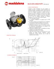
Temperature SensorsFor Heat/Cooling MetersCS-5.X/CST-5.XType PT500DE-06-MI004-PTB00922.77 / 08.02Instalaltion and Operating Instructions1 Application and FunctionThe <strong>temperature</strong> sensor pairs for heat/cooling meters CS-5.x orCST-5.x types PT... have EC type examination certification orGerman national PTB approval and are designed for connectionto calculators of heat/cooling meters.2 Content of the Package1. Temperature sensor CS-5.x / CST-5.x2. Installation kit3. Installation and Operating Instructions3 General Information Valid statutory provisions and standards for the applicationof <strong>temperature</strong> sensor pairs for the measurement of theforward and return flow <strong>temperature</strong>s of a heat exchangesystem:- EN 1434:2007, 1 + 6- Directive 2004/22/EC (MID), Annexes I and MI-004- German verification regulation annex 22 TR-K 7.1 / 7.2 The regulations for electrical installations must be adheredto. The <strong>temperature</strong> <strong>sensors</strong> left the factory in conformancewith all applicable safety regulations. Installation and all maintenance work may only be carriedout by qualified and authorized technical personnel. All details and specifications listed in the <strong>temperature</strong>sensor data sheet or in these installation and operatinginstructions must be adhered to. Verification seals and sensor identification must not bedamaged or removed – otherwise the guarantee andverification of the <strong>sensors</strong> no longer apply! Sensor cables must be laid at a minimum distance of 20 cmto sources of electromagnetic interference (switches,controllers, pumps etc.) Sensor cables must be laid at a minimum distance of 5 cmto other current-carrying wires. To protect against damage and dirt the <strong>temperature</strong> <strong>sensors</strong>should only be removed from the packaging directly beforeinstallation. The applicable verification regulations in the country inwhich the <strong>sensors</strong> are to be installed must be observed. The forward flow sensor (red identification label on thecable) must always be installed in the forward flow The return flow sensor (blue identification label on the cable)must always be installed in the return flow. When possible, the <strong>temperature</strong> <strong>sensors</strong> should always bemounted against the direction of flow. The <strong>temperature</strong> <strong>sensors</strong> are not to be installed within theinfluence of other sources of heat. Do not kink, lengthen or shorten the <strong>temperature</strong> sensorcables. Cables that are too long should not be coiled. Always connect the <strong>temperature</strong> <strong>sensors</strong> to the calculatorbefore connecting the flow meter.4 Direct Mounting4.1 Direct mounting in T-piece Remove the blind plug andthe gasket. Clean the sealingsurface. Slide the O-ring off the<strong>temperature</strong> sensor andplace it at the bottom of theopening. The O-ring must nottouch the thread. Slide the sealing screw nutup to the O-ring. Holding the screw nut inplace, insert the sensor into the T-piece and tighten thescrew nut firmly to the stop.4.2 Direct mounting in ball valve and T-piece Remove the blind plug/old <strong>temperature</strong>sensor and gasket/old O-ring. Cleanconnection surfaces. Slide the O-ring off the <strong>temperature</strong> sensorand insert it to the bottom of the opening ofthe ball valve or the T-piece. Set the required mounting depth of the tip ofthe <strong>temperature</strong> sensor by tightening thecross-head screw in the correct beading onthe sheath. The <strong>temperature</strong> sensor must not touch the bottom of theball valve or T-piece. Insert the <strong>temperature</strong> sensor into the ball valve or the T-piece and tighten the screw nut to the stop.5 Sealing the Temperature SensorAfter a function test, but before starting up operation, the<strong>sensors</strong> and connection pieces must be properly sealed.Important note:The seals may not be damaged or removed, otherwise theguarantee and verification of the <strong>sensors</strong> no longer apply!6 Connection of Temperature Sensors to theCalculatorNote: The illustrated connection diagrams are only examples.The actual order of the connections can vary depending on thecalculator used. Follow the specifications and installation instructions of thecalculator to which the <strong>temperature</strong> <strong>sensors</strong> are beingconnected! The numbering of the terminal connectors corresponds tothe standard (EN1434-2) and must be adhered to.6.1 2-wire connectionForward flow <strong>temperature</strong> sensor (red identification labelon the cable):clamp 5 (brown) and clamp 6 (blue)Return flow <strong>temperature</strong> sensor (blue identification label onthe cable):clamp 7 (brown) and clamp 8 (blue)1081100005 – 2011-03-23 Rev.1 1
6.2 4-wire connectionForward flow <strong>temperature</strong> sensor (red identification labelon the cable):clamp 1 (brown) and clamp 5 (yellow)clamp 6 (green) and clamp 2 (white)Return flow <strong>temperature</strong> sensor (blue identification label onthe cable):clamp 3 (brown) and clamp 7 (yellow)clamp 8 (green) and clamp 4 (white)Details type CS-5.x / CST-5.x PT100/500/1000Temperature measurement rangeHeatTemperature differenceHeat 0 ... 150 °C: minimal 3K: maximal 150KTemperature measurement rangeCooling : 0 ... 150 °CTemperature differenceCooling-: minimal 3K-: maximal 50KUpper <strong>temperature</strong> limit 150 °C7 MaintenanceTo ensure measurement stability, after expiration of the nationalstatutory verification period an examination of the <strong>temperature</strong><strong>sensors</strong> must be carried out to check adherence to themaximum permitted error (MPE) according to EN 1434:2007.8 Technical DataTemperature <strong>sensors</strong>TypeNominal valueDiameterNominal lengthplatinum precision resistor(DIN EN 60751)PT500, optional PT100 and PT10005 <strong>mm</strong> or 5.2 <strong>mm</strong>46 <strong>mm</strong>Sheath beading type CS: 2 ; type CST: 3Cable lengthTotal resistance(2-wire cable)Maximum electricalmeasurement powerInstallationMinimum i<strong>mm</strong>ersiondepthResponse timeMeasurement stabilityup to 3 m in 2-wire technique (PT100)up to 10 m in 2-wire technique(PT500, PT1000)up to 10 m in 4-wire technique(PT100, PT500, PT1000)0,14 Ohm/mfor 0,25 <strong>mm</strong>² wire cross-section0.3 mW (for pulsed measurementcurrents the average value applies)direct-mounted (type DS)direct-mounted: 15 <strong>mm</strong> ≤ 4 s10 years (upon observance ofmaintenance specifications)Maximum pressure PN 169 Declaration of ConformityFor the product described in this document we confirm, as themanufacturer, that it meets the fundamental requirementsaccording to: Council Directive 2004/22/EC of 31 March 2004 on theapproximation of the laws of the member states relating tomeasurement instruments, in particular those in annex MI-004 European Council Directive on EMC 2004/108/EC Council Low Voltage Directive 2006/95/EC.The complete signed declaration can be found atwww.engelmann.de.10 Contacts<strong>Maddalena</strong> S.p.A.Via G.B. <strong>Maddalena</strong>, 2/433040 Povoletto (UD) ItalyTel.: +39.0432.634811Fax.: +39.0432.679820www.maddalena.itSubject to technical change.Environmental class class E1, M1 as per EN 1434 : 2007Protection ratingIP651081100005 – 2011-03-23 Rev.1 2