23 Series And Parallel Circuits - Vernier Software & Technology
23 Series And Parallel Circuits - Vernier Software & Technology
23 Series And Parallel Circuits - Vernier Software & Technology

Create successful ePaper yourself
Turn your PDF publications into a flip-book with our unique Google optimized e-Paper software.
_____________________________________________________________________________________The City of Roanoke is an employer committed to public service, equal opportunity and theimportance of diversity in the workplace. Pre-employment screenings are administered to allemployees.For details or questions, contact the HR Recruiter, Dawn C. Board at (540) 853-2138.To apply and review the full job description visit: www.roanokeva.gov/jobs or complete anapplication in person at 215 Church Ave, SW, Roanoke, VA 24011, Room 207.
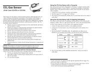
Computer <strong>23</strong>16. Repeat Steps 13–15 with a 68 Ω resistor substituted for resistor 2.17. Repeat Steps 13–15 with a 68 Ω resistor used for both resistor 1 and resistor 2.Part III Currents in <strong>Series</strong> and <strong>Parallel</strong> circuits18. For Part III of the experiment, you will use two Current Probes. Open the experiment file“<strong>23</strong>b <strong>Series</strong> <strong>Parallel</strong> Circ.” Two graphs of current vs. time are displayed.19. Disconnect the Voltage Probe and, into the same channel, connect a second Current Probe.20. With nothing connected to either probe, click , then click to zero both sensors.This adjusts the current reading to zero with no current flowing.21. Connect the series circuit shown in Figure 4 using the 10 Ω resistor and the 51 Ω resistor.The Current Probes will measure the current flowing into and out of the two resistors. Thered terminal of each Current Probe should be toward the + terminal of the power supply.Figure 422. For this part of the experiment, you will make a graph of the current measured by each probeas a function of time. You will start the graphs with the switch open, close the switch for afew seconds, and then release the switch. Before you make any measurements, think aboutwhat you would expect the two graphs to look like. Sketch these graphs showing yourprediction. Note that the two resistors are not equal.<strong>23</strong>. Click on the button, wait a second or two, then press on the switch to complete thecircuit. Release the switch just before the graph is completed.24. Select the region of the graph where the switch was on by dragging the cursor over it. Clickon the Statistics button, , and record the average current in the data table. Determine theaverage current in the second graph following the same procedure.25. Connect the parallel circuit as shown in Figure 5 using the 51 Ω resistor and the 68 Ωresistor. The two Current Probes will measure the current through each resistor individually.The red terminal of each Current Probe should be toward the + terminal of the power supply.<strong>23</strong> - 4 Physics with <strong>Vernier</strong>
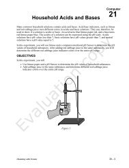
<strong>Series</strong> and <strong>Parallel</strong> <strong>Circuits</strong>Figure 526. Before you make any measurements, sketch your prediction of the current vs. time graphs foreach Current Probe in this configuration. Assume that you start with the switch open asbefore, close it for several seconds, and then open it. Note that the two resistors are notidentical in this parallel circuit.27. Click and wait a second or two. Then press on the switch to complete the circuit.Release the switch just before the graph is completed.28. Select the region of the graph where the switch was on by dragging the cursor over it. Clickthe Statistics button, , and record the average current in the data table. Determine theaverage current in the second graph following the same procedure.DATA TABLEPart I <strong>Series</strong> <strong>Circuits</strong>Part I: <strong>Series</strong> circuitsR 1(Ω)R 2(Ω)I(A)V 1(V)V 2(V)Req(Ω)V TOT(V)1 10 102 10 513 51 51Part II: <strong>Parallel</strong> circuitsR 1(Ω)R 2(Ω)I(A)V 1(V)V 2(V)Req(Ω)V TOT(V)1 51 512 51 683 68 68Physics with <strong>Vernier</strong> <strong>23</strong> - 5
Computer <strong>23</strong>Part III: CurrentsR 1(Ω)R 2(Ω)I 1(A)I 2(A)1 10 512 51 68ANALYSIS1. Examine the results of Part I. What is the relationship between the three voltage readings: V 1 ,V 2 , and V TOT ?2. Using the measurements you have made above and your knowledge of Ohm’s law, calculatethe equivalent resistance (R eq ) of the circuit for each of the three series circuits you tested.3. Study the equivalent resistance readings for the series circuits. Can you come up with a rulefor the equivalent resistance (R eq ) of a series circuit with two resistors?4. For each of the three series circuits, compare the experimental results with the resistancecalculated using your rule. In evaluating your results, consider the tolerance of each resistorby using the minimum and maximum values in your calculations.5. Using the measurements you have made above and your knowledge of Ohm’s law, calculatethe equivalent resistance (R eq ) of the circuit for each of the three parallel circuits you tested.6. Study the equivalent resistance readings for the parallel circuits. Devise a rule for theequivalent resistance of a parallel circuit of two resistors.7. Examine the results of Part II. What do you notice about the relationship between the threevoltage readings V 1 , V 2 , and V TOT in parallel circuits.8. What did you discover about the current flow in a series circuit in Part III?9. What did you discover about the current flow in a parallel circuit in Part III?10. If the two measured currents in your parallel circuit were not the same, which resistor had thelarger current going through it? Why?EXTENSIONS1. Try this experiment using three resistors in series and in parallel.2. Try Part III of this experiment using small lamps instead of resistors. Can you explain thechange in the shape of the current vs. time graphs?<strong>23</strong> - 6 Physics with <strong>Vernier</strong>
<strong>Vernier</strong> Lab Safety Instructions DisclaimerTHIS IS AN EVALUATION COPY OF THE VERNIER STUDENT LAB.This copy does not include:• Safety information• Essential instructor background information• Directions for preparing solutions• Important tips for successfully doing these labsThe complete Physics with <strong>Vernier</strong> lab manual includes 35 labs and essential teacherinformation. The full lab book is available for purchase at:http://www.vernier.com/cmat/pwv.html<strong>Vernier</strong> <strong>Software</strong> & <strong>Technology</strong>13979 S.W. Millikan Way • Beaverton, OR 97005-2886Toll Free (888) 837-6437 • (503) 277-2299 • FAX (503) 277-2440info@vernier.com • www.vernier.com