CHOFORM 5550 and 5541 Compression/Deflection - Darcoid
CHOFORM 5550 and 5541 Compression/Deflection - Darcoid
CHOFORM 5550 and 5541 Compression/Deflection - Darcoid
You also want an ePaper? Increase the reach of your titles
YUMPU automatically turns print PDFs into web optimized ePapers that Google loves.
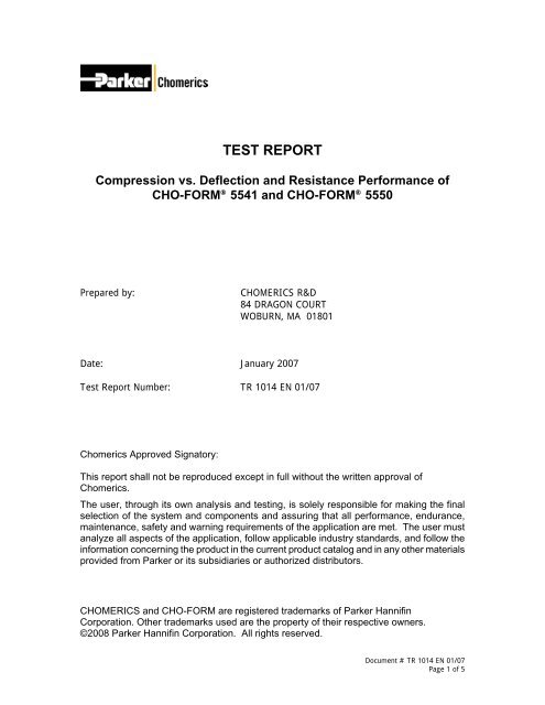
TEST REPORT<strong>Compression</strong> vs. <strong>Deflection</strong> <strong>and</strong> Resistance Performance ofCHO-FORM ® <strong>5541</strong> <strong>and</strong> CHO-FORM ® <strong>5550</strong>Prepared by:CHOMERICS R&D84 DRAGON COURTWOBURN, MA 01801Date: January 2007Test Report Number: TR 1014 EN 01/07Chomerics Approved Signatory:This report shall not be reproduced except in full without the written approval ofChomerics.The user, through its own analysis <strong>and</strong> testing, is solely responsible for making the finalselection of the system <strong>and</strong> components <strong>and</strong> assuring that all performance, endurance,maintenance, safety <strong>and</strong> warning requirements of the application are met. The user mustanalyze all aspects of the application, follow applicable industry st<strong>and</strong>ards, <strong>and</strong> follow theinformation concerning the product in the current product catalog <strong>and</strong> in any other materialsprovided from Parker or its subsidiaries or authorized distributors.CHOMERICS <strong>and</strong> CHO-FORM are registered trademarks of Parker HannifinCorporation. Other trademarks used are the property of their respective owners.©2008 Parker Hannifin Corporation. All rights reserved.Document # TR 1014 EN 01/07Page 1 of 5
Introduction:CHO-FORM ® <strong>5541</strong> <strong>and</strong> CHO-FORM ® <strong>5550</strong> are single component, thermally cured,electrically conductive form-in-place (FIP) elastomers specifically formulated to provideshielding against electromagnetic interference (EMI). Both products contain nickel-platedgraphite particles dispersed within a silicone elastomer.While CHO-FORM ® <strong>5541</strong> (75 +/-8 Shore A durometer hardness) continues to besuccessfully employed in a variety of applications where corrosion resistance <strong>and</strong> longterm stability are crucial, CHO-FORM ® <strong>5550</strong> (43 +/-8 Shore A durometer hardness) hasbeen developed to provide our customers with a lower hardness alternative to addressapplications where seal hardness greater than 70 Shore-A may be impractical <strong>and</strong> costprohibitive from a design perspective.This test report examines the percent deflection versus applied load as well as thepercent deflection versus electrical through resistance of both CHO-FORM ® <strong>5541</strong> <strong>and</strong>CHO-FORM ® <strong>5550</strong>.Test Set-Up <strong>and</strong> Configuration:Test MethodBoth the compression deflection <strong>and</strong> compression resistance were evaluated perChomerics Document Number: NBD-001 Rev. 1.0 - <strong>Compression</strong><strong>Deflection</strong>/<strong>Compression</strong> Resistance Test Procedure.Test Specimens <strong>and</strong> Sample PreparationThe compression deflection <strong>and</strong> compression resistance testing was performed on alinear bead 1.00” (25.40 mm) in length <strong>and</strong> 0.05” (1.27 mm) in height.The test specimens were dispensed <strong>and</strong> cured per the manufacturing processinstructions <strong>and</strong> conditioned for a minimum of 3 hours at ambient room temperature (23+/- 5°C <strong>and</strong> 50 +/- 5% R.H.) prior to testing.EquipmentTo perform the evaluation, the following equipment was utilized:- A Texture Technologies Corp. TA-HD Plus Texture Analyzer equipped with a 750 kgload cell operated at a test speed of 0.025 in/min (0.064 mm/min) from 0% through50% deflection fitted with a 1.00” (25.4 mm) by 1.00” (25.4 mm) copper probe.- A digital ohmmeter with a measurement range of 0 to 20,000 mohm.Experimental Results:Percent <strong>Deflection</strong> versus Applied LoadApplied load measurements were recorded over a percent deflection range of 1%through 50%. The overall percent deflection versus applied load has been plotted inDocument # TR 1014 EN 01/07Page 2 of 5
Figure 1. Applied load data at specific deflection intervals is summarized in Table 1.<strong>Deflection</strong> vs. Applied LoadLoad (lbf / in)15012510075502545040035030025020015010050Load (N / cm)000 5 10 15 20 25 30 35 40 45 50<strong>Deflection</strong> (%)CHO-FORM® <strong>5550</strong> CHO-FORM® <strong>5541</strong>Figure 1: <strong>Deflection</strong> vs. Applied Load: CHO-FORM ® <strong>5541</strong> <strong>and</strong> CHO-FORM ® <strong>5550</strong>1.00” (25.40 mm) x 0.05” (1.27 mm) dispensed bead.<strong>Deflection</strong> (%)5 10 20 30 40 50Applied LoadCHO-SEAL ® <strong>5550</strong>CHO-SEAL ® <strong>5541</strong>lb f / in 0.81 2.34 6.89 18.15 46.66 90.72N / cm 1.42 4.10 12.07 31.79 81.71 158.88lb f / in 4.44 10.44 22.98 45.14 83.47 147.99N / cm 7.77 18.29 40.24 79.05 146.18 259.18Table 1: <strong>Deflection</strong> vs. Applied Load: CHO-FORM ® <strong>5541</strong> <strong>and</strong> CHO-FORM ® <strong>5550</strong> – Points of Reference1.00” (25.40 mm) x 0.05” (1.27 mm) dispensed bead.Percent <strong>Deflection</strong> versus Electrical Through ResistanceElectrical through resistance measurements were recorded over a percent deflectionrange of 1% through 50%. The overall percent deflection versus applied load data hasbeen plotted in Figure 2 with points of reference summarized in Table 2.Document # TR 1014 EN 01/07Page 3 of 5
<strong>Deflection</strong> vs. Through Resistance250Through Resistance (mohm / 25.4 mm)22520017515012510075502500 5 10 15 20 25 30 35 40 45 50<strong>Deflection</strong> (%)CHO-FORM® <strong>5550</strong> CHO-FORM® <strong>5541</strong>Figure 2: <strong>Deflection</strong> vs. Resistance: CHO-FORM ® <strong>5541</strong> <strong>and</strong> CHO-FORM ® <strong>5550</strong>1.00” (25.40 mm) x 0.05” (1.27 mm) dispensed bead.<strong>Deflection</strong> (%)5 10 20 30 40 50Through ResistanceCHO-SEAL ® <strong>5550</strong> mohm / 25.4 mm 89.0 40.5 19.0 6.5 4.0 1.0CHO-SEAL ® <strong>5541</strong> mohm / 25.4 mm 58.0 16.0 12.0 6.0 5.5 5.0Table 2: <strong>Deflection</strong> vs. Resistance: CHO-FORM ® <strong>5541</strong> <strong>and</strong> CHO-FORM ® <strong>5550</strong> – Points of Reference1.00” (25.40 mm) x 0.05” (1.27 mm) dispensed bead.Conclusions:It is strongly recommended that customers work with the Chomerics ApplicationsDepartment to model <strong>and</strong> prototype solutions to a given unique set of applicationrequirements.Percent <strong>Deflection</strong> versus Applied LoadWhen evaluating a 1.00” (25.40 mm) x 0.05” (1.27 mm) dispensed bead, the appliedDocument # TR 1014 EN 01/07Page 4 of 5
load required to deflect CHO-FORM ® <strong>5550</strong> was approximately 40 to 80% less than loadneeded to deflect CHO-FORM ® <strong>5541</strong> at the equivalent deflection intervals listed in Table3 below:<strong>Deflection</strong> ( %)5 10 20 30 40 50CHO-SEAL ® <strong>5550</strong> % Delta -81.7% -77.6% -70.0% -59.8% -44.1% -38.7%Table 3: Percent Difference of Applied Load at Select <strong>Deflection</strong> Intervals:CHO-FORM ® <strong>5550</strong> vs. CHO-FORM ® <strong>5541</strong>1.00” (25.40 mm) x 0.05” (1.27 mm) dispensed bead.Percent <strong>Deflection</strong> versus Electrical Through ResistanceThough dependent on sample geometry, the percent deflection versus electrical throughresistance for the samples described within this test report, indicates that the electricalthrough resistance of CHO-FORM ® <strong>5541</strong> <strong>and</strong> CHO-FORM ® <strong>5550</strong> are approximatelyequivalent through a deflection range of 15 through 50 percent.Document # TR 1014 EN 01/07Page 5 of 5


