POWERPOINT® PP-S/ PP-B/ PP-VIP User Instructions - Part ... - RUD
POWERPOINT® PP-S/ PP-B/ PP-VIP User Instructions - Part ... - RUD
POWERPOINT® PP-S/ PP-B/ PP-VIP User Instructions - Part ... - RUD

You also want an ePaper? Increase the reach of your titles
YUMPU automatically turns print PDFs into web optimized ePapers that Google loves.
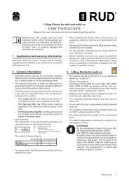
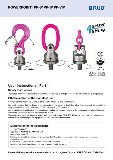
POWERPOINT ® <strong>PP</strong>-S/ <strong>PP</strong>-B/ <strong>PP</strong>-<strong>VIP</strong>Complies with the machinery directives 2006/42/ECorotation180360° rotationMO075110Gauge marks todetermine overload<strong>User</strong> <strong>Instructions</strong> - <strong>Part</strong> 1Safety instructionsThis safety instruction / declaration of the manufacturer has to be kept on file for the whole lifetime of the product.EC-Declaration of the manufacturerAccording to the Machinery Directive 2006/42/EC, annex II B and amendments.We hereby declare that the design and construction of the equipment detailed within this document, adheres to theappropriate level of health and safety of the corresponding EC regulation.Any un-authorised modification of the equipment and/or any incorrect usage of the equipment not adhered to withinthese user instructions waivers this declaration invalid.The equipment must be regularly tested and inspected as per BGR 500. Failure to carry out the recommendedmaintenance and testing of the equipment waivers this declaration invalid.Designation of the equipment:Lifting pointType: Power Point ® <strong>PP</strong>-S / <strong>PP</strong>-B / <strong>PP</strong>-<strong>VIP</strong>Manufacturer’s sign:Drawings are available on request as hard copies or DXF files. Drawings can also be downloaded from our website:www.rud.com.au.Check the <strong>RUD</strong> website: www.rud.com.au for product information.Workshop wall charts available upon request for working load limits (WLL).Please visit our website at www.rud.com.au to register for your FREE CD with CAD Files
POWERPOINT ® <strong>PP</strong>-S/ <strong>PP</strong>-B/ <strong>PP</strong>-<strong>VIP</strong><strong>User</strong> <strong>Instructions</strong> - <strong>Part</strong> 2<strong>RUD</strong> PowerPoint ® are available in the following versions:<strong>PP</strong>-S: the standard version<strong>PP</strong>-B: the lifting ring version for hook assemblies<strong>PP</strong>-<strong>VIP</strong>: the direct chain connectionAttention: Other combinations with non <strong>RUD</strong> liftingcomponents maybe dangerous! These are not permittedand <strong>RUD</strong> will not accept any warranty claim.<strong>User</strong> <strong>Instructions</strong>1. Reference should be made to relevant standards and otherstatutory regulations. Inspections should be carried out bycompetent persons only.2. Before installation and at every use, visually inspect<strong>RUD</strong> lifting points, with particular attention to any evidenceof corrosion, wear, weld cracks and deformations. Pleaseensure compatibility of bolt thread and tapped hole.3. The material construction to which the lifting point will beattached, should be of adequate strength to withstand forcesduring lifting without deformation. <strong>RUD</strong>, with reference tothe German testing authority BG, recommends the followingminimum for bolt lengths:• 1.5 x M in steel (minimum quality S235JR [1.0037])≈ AS3678 GR250.• 1.5 x M in cast iron (for example GG 25)• 2 x M in aluminium alloys• 2.5 x M in aluminium-magnesium alloys• ( M = diameter of <strong>RUD</strong> lifting point bolt, e.g. M 20 )When lifting light metals, nonferrous heavy metals andgray cast iron, the thread has to be chosen in such a waythat the working load limit of the thread corresponds to therequirements of the respective base material.4. The lifting points must be positioned to the load in such away that movements are avoided during lifting.a) For single leg lifts, the lifting point should be verticallyabove the centre of gravity of the load.b) For two leg lifts, the lifting points must be equidistant to/orabove the centre of gravity of the load.c) For three and four leg lifts, the lifting points should bearranged symmetrical around the centre of gravity, in thesame plane if possible.5. Load Symmetry: The working load limits of individual <strong>RUD</strong>lifting points are calculated using the following formula andare based on symmetrical loading:WLL =Gn x cos ßWLLGnß= required of lifting point/individual leg (kg)= load weight (kg)= number of load bearing legs= angle of inclination of the individual legNOTE: For WLL Calculations• ß angle is taken from the vertical plane.• Included angle is the angle between the sling legs.6. Safety: When lifting points are used in a multi leg assembly,care should be taken to calculate the WLL (Working LoadLimit) due to the deration caused by forces acting in multipledirections. The reduction in WLL (Working Load Limit) for multileg assemblies should be checked with relevant Standardse.g. AS 3775-2004 - Chain Slings-Gr t (8)7. A plane bolting surface must be guaranteed to ensurecorrect mating of the lift component.<strong>PP</strong>-S <strong>PP</strong>-B <strong>PP</strong>-<strong>VIP</strong>9. Drill and tap the work piece so that the PowerPoint ® - versionis installed perpendicular to the surface of the work piece.The work piece surface must be flat, providing completecontact for the PowerPoint ® -version ball bearing housing.Countersink the tapped hole.9. For single use it is sufficient to tighten by hand with aspanner. For a long term application the PowerPoint ® shouldbe tightened to torque according to relevant table (+/- 10%).10. The <strong>RUD</strong> PowerPoint ® versions are designed for turningand rotating of loads, however, not for permanent, continuousrotations under load!11. All fittings connected to the PowerPoint ® -versions shouldbe free moving. Also the assembled components on thePowerPoint ® must be free moving and should not be usedover sharp corners.When connecting and disconnecting the lifting means (wireropes, chain slings, round slings) pinches and impacts shouldbe avoided. Damage to lifting components caused by sharpcorners should also be avoided.Adjust to the direction of pull before attaching to the liftingmeans.12. To prevent unintended dismounting through shockloading, rotation or vibration, thread locking fluid such asLoctite (depending on the application, please refer to themanufacturer’s instruction) should be used to secure thebolt.13. Effect of temperature: Due to the lubrication, <strong>RUD</strong>recommends that PowerPoint ® - versions are not used in hightemperature applications. If this cannot be avoided pleasetake the reduced WLL into consideration:-10° up to 200°C no reduction (14°F up to 392°F)200° up to 300°C minus 10% (392°F up to 572°F)300° up to 400°C minus 25% (572°F up to 752°F)Temperatures above 400°C (752°F) are not allowed.14. <strong>RUD</strong> lifting points must not be used under chemicalinfluences such as acids, alkaline solutions and vapours e.g.in pickling baths or hot dip galvanising plants. If this cannotbe avoided, please contact the manufacturer indicating theconcentration, period of penetration and temperature of use.15. The PowerPoint ® - versions are available with differentthread lengths (refer to F Vario in table 1). The assembly ofcomponents must only be carried out by <strong>RUD</strong> or authorisedspecialists.For the user it is not recommended to disassemble theball bearing housing.16. After fitting, an annual inspection or sooner if conditionsdictate should be undertaken by a competent personexamining the continued suitability. Also inspect after damageand special occurrences.
POWERPOINT ® <strong>PP</strong>-S/ <strong>PP</strong>-B/ <strong>PP</strong>-<strong>VIP</strong><strong>User</strong> <strong>Instructions</strong> - <strong>Part</strong> 3Inspection criteria regarding paragraphs 2 and 16:• Ensure correct bolt size, quality and length.• Ensure compatibility of bolt thread and tapped hole - controlof the torque.• The lifting point should be complete.• The WLL, thread size, batch code and manufacturersstamping should be clearly visible on the lifting point.• Deformations of the components parts such as body,fittings and thread.• Mechanical damages such as notches, especially in highstress areas.• Wear should be not more than 10% of cross sectionaldiameter.• Evidence of corrosion.Any non-adherence to this advice may result in damages of persons and / or materials.• Evidence of cracks.• Damage to the bolt and/or thread.• The upper fork head part of the PowerPoint ®- versionsmust rotate smoothly.• The PowerPoint ®- versions should only be used within thenom WLL. See <strong>RUD</strong> chart.• Due to double bearing races, proof testing is not suitablefor the PowerPoint range. Testing should be MPI (Magnetic<strong>Part</strong>ical Inspection) and visual.• The maximum gap between upper- and lower part of thePowerPoint ® must not be exceeded:<strong>PP</strong>-..-0.63t up to <strong>PP</strong>-..2.5t max. 1.5 mm<strong>PP</strong>-..-4t up to <strong>PP</strong>-..8tmax. 2.5 mm<strong>PP</strong>-S <strong>PP</strong>-B <strong>PP</strong>-<strong>VIP</strong>and Vario lengths variantsOnly for original <strong>VIP</strong> chainTypeWLL(t)A B C D E FStandardFVarioG M T Weight(kg)torqueRef-no.StandardRef-no.Vario<strong>PP</strong>-S-0.63t-M12 0.63 13 75 18 40 36 18 19-145* 41 12 116 0.4 10 Nm 7990719 8600320<strong>PP</strong>-S-1.5t-M16 1.5 20 97 25 46 41 25 26-180* 50 16 147 1.0 30 Nm 7989719 8600321<strong>PP</strong>-S-2.5t-M20 2.5 28 126 30 61 55 30 31-200 61 20 187 1.7 70 Nm 7989075 8600302<strong>PP</strong>-S-4t-M24 4.0 36 150 35 78 70 36 37-255* 77 24 227 3.5 150 Nm 7989076 8600323<strong>PP</strong>-S-5t-M30 5.0 37 174 40 95 85 45 46-330 93 30 267 7.2 225 Nm 7989720 8600324<strong>PP</strong>-S-8t-M36 8.0 49 208 48 100 90 54 55-300 102 36 310 9.2 410 Nm 7989077 8600305<strong>PP</strong>-B-0.63t-M12 0.63 9 65 35 40 36 18 19-145* 41 12 105 0.35 10 Nm 7989522 8600320<strong>PP</strong>-B-1.5t-M16 1.5 11 65 35 46 41 25 26-180* 50 16 115 0.6 30 Nm 7989523 8600321<strong>PP</strong>-B-2.5t-M20 2.5 13 74 40 61 55 30 31-200 61 20 135 1.1 70 Nm 7989081 8600302<strong>PP</strong>-B-4t-M24 4.0 16 95 45 78 70 36 37-255* 77 24 172 2.4 150 Nm 7989082 8600323<strong>PP</strong>-B-5t-M30 5.0 19 130 60 95 85 45 46-330 93 30 223 5.2 225 Nm 7989524 8600324<strong>PP</strong>-B-8t-M36 8.0 24 140 65 100 90 54 55-300 102 36 242 6.3 410 Nm 7989083 8600305<strong>PP</strong>-<strong>VIP</strong>-0.63t-M12 0.63 4 - - 40 36 18 19-145* - 12 41 0.25 10 Nm 7989525 8600320<strong>PP</strong>-<strong>VIP</strong>-1.5t-M16 1.5 6 - - 46 41 25 26-180* - 16 50 0.45 30 Nm 7989526 8600321<strong>PP</strong>-<strong>VIP</strong>-2.5t-M20 2.5 8 - - 61 55 30 31-200 - 20 61 0.95 70 Nm 7989527 8600302<strong>PP</strong>-<strong>VIP</strong>-4t-M24 4,0 10 - - 78 70 36 37-255* - 24 77 2,2 150 Nm 7989528 8600323<strong>PP</strong>-<strong>VIP</strong>-5t-M30 5,0 13 - - 95 85 45 46-330 - 30 93 3,5 225 Nm 7989529 8600324<strong>PP</strong>-<strong>VIP</strong>-8t-M36 8,0 16 - - 100 90 54 55-300 - 36 102 5,2 410 Nm 7989530 8600305Table 1
POWERPOINT ® <strong>PP</strong>-S/ <strong>PP</strong>-B/ <strong>PP</strong>-<strong>VIP</strong><strong>User</strong> <strong>Instructions</strong> - <strong>Part</strong> 4WORKING LOAD LIMITS (G - in tonnes)PRODUCTDESCRIPTIONSingleLegSingleLeg2 , 3 or 4 Legs60° 90° 120°Maximum Included Angle (Degrees)<strong>PP</strong> - S / <strong>PP</strong> - B M12 0.63 0.63 1.1 0.89 0.63<strong>PP</strong> - S / <strong>PP</strong> - B M16 1.5 1.5 2.6 2.1 1.5<strong>PP</strong> - S / <strong>PP</strong> - B M20 2.5 2.5 4.3 3.5 2.5<strong>PP</strong> - S / <strong>PP</strong> - B M24 4.0 4.0 6.9 5.6 4.0<strong>PP</strong> - S / <strong>PP</strong> - B M30 6.7 5.0 8.6 7.0 5.0<strong>PP</strong> - S / <strong>PP</strong> - B M36 10.0 8.0 13.8 11.3 8.0Table 2<strong>PP</strong>-S <strong>PP</strong>-B <strong>PP</strong>-<strong>VIP</strong>and Vario lengths variantsOnly for original <strong>VIP</strong> chainTypeWLL(lbs)<strong>PP</strong>-S-0.63t-1/2”-13UNC 13851/ 2 2 15/ 16A B C D E FStandard23/ 32 1 9/ 16 1 13/ 32FVario23/ 321/ 2 -1 3/ 4 1 5/ 8G M T Weight(lbs)torqueRef-no.Standard1/ 2 4 9/ 16 0.9 10 Nm 7990720<strong>PP</strong>-S-1.5t-5/8”-11UNC 330023/ 32 3 13/ 16 1 1 13/ 16 1 5/ 8 15/ 8 -2 5/ 32 25/ 8 5 3/ 4 2.0 30 Nm 7989908<strong>PP</strong>-S-2.5t-3/4”-10UNC 5500 1 1/ 8 5 1 3/ 16 2 13/ 32 2 5/ 32 1 3/ 16 - 2 13/ 32<strong>PP</strong>-S-2.5t-7/8”-9UNC 5500 1 1/ 8 5 1 3/ 16 2 13/ 32 2 5/ 32 1 3/ 16 - 2 13/ 323/ 4 7 3/ 8 3.7 70 Nm 79899097/ 8 7 3/ 8 3.8 80 Nm 7989910<strong>PP</strong>-S-4t-1”-8UNC 8800 1 13/ 32 5 7/ 8 1 3/ 8 3 2 3/ 4 1 13/ 32 1 -2 29/ 32 3 1 8 15/ 16 7.7 150 Nm 7989911<strong>PP</strong>-S-5t-11/4”-7UNC 11000 1 7/ 16 6 7/ 8 1 9/ 16 3 3/ 4 3 11/ 32 1 3/ 4 1 1/ 4 -3 9/ 16 3 5/ 8 1 1/ 4 10 1/ 2 14.3 225 Nm 7989912<strong>PP</strong>-S-8t-11/2”-6UNC 17600 1 15/ 16 8 3/ 16 1 7/ 8 3 15/ 16 3 9/ 16 2 1/ 8 2 1/ 8 -11 3/ 4 4 1 1/ 2 12 3/ 16 20.2 410 Nm 7989913<strong>PP</strong>-B-0.63t-1/2”-13UNC 13853/ 8 2 9/ 16 1 3/ 8 1 9/ 16 1 13/ 3223/ 321/ 2 -1 3/ 4 1 5/ 81/ 2 4 1/ 8 0.8 10 Nm 7989901<strong>PP</strong>-B-1.5t-5/8”-11UNC 33007/ 16 2 9/ 16 1 3/ 8 1 13/ 16 1 5/ 8 15/ 8 -2 5/ 32 25/ 8 4 1/ 2 1.3 30 Nm 7989902<strong>PP</strong>-B-2.5t-3/4”-10UNC 55001/ 2 2 7/ 8 1 9/ 16 2 13/ 32 2 5/ 32 1 3/ 16 - 2 13/ 32<strong>PP</strong>-B-2.5t-7/8”-9UNC 55001/ 2 2 7/ 8 1 9/ 16 2 13/ 32 2 5/ 32 1 3/ 16 - 2 13/ 323/ 4 5 5/ 16 2.4 70 Nm 79899037/ 8 5 5/ 16 2.5 80 Nm 7989904<strong>PP</strong>-B-4t-1”-8UNC 88005/ 8 3 3/ 4 1 3/ 4 3 2 3/ 4 1 13/ 32 1 -2 29/ 32 3 1 6 3/ 4 5.3 150 Nm 7989905<strong>PP</strong>-B-5t-11/4”-7UNC 110003/ 4 5 1/ 8 2 3/ 8 3 3/ 4 3 11/ 32 1 3/ 4 1 1/ 4 -3 9/ 16 3 5/ 8 1 1/ 4 8 3/ 4 11.6 225 Nm 7989906<strong>PP</strong>-B-8t-11/2”-6UNC 1760015/ 16 5 1/ 2 2 9/ 16 3 15/ 16 3 9/ 16 2 1/ 8 2 1/ 8 -11 3/ 4 4 1 1/ 2 9 1/ 2 13.8 410 Nm 7989907<strong>PP</strong>-<strong>VIP</strong>-0.63t-1/2”-13UNC 13855/ 32 - - 1 9/ 16 1 13/ 3223/ 321/ 2 -1 3/ 4 -1/ 2 1 5/ 8 0.55 10 Nm 7989920<strong>PP</strong>-<strong>VIP</strong>-1.5t-5/8”-11UNC 330015/ 16 - - 1 13/ 16 1 5/ 8 15/ 8 -2 5/ 32 -5/ 8 2 1.0 30 Nm 7989921<strong>PP</strong>-<strong>VIP</strong>-2.5t-3/4”-10UNC 55005/ 16 - - 2 13/ 32 2 5/ 32 1 3/ 16 - -3/ 4 2 13/ 32 2.0 70 Nm 7989922<strong>PP</strong>-<strong>VIP</strong>-2.5t-7/8”-9UNC 55005/ 16 - - 2 13/ 32 2 5/ 32 1 3/ 16 - -7/ 8 2 13/ 32 2.2 80 Nm 7989923<strong>PP</strong>-<strong>VIP</strong>-4t-1”-8UNC 88003/ 8 - - 3 2 3/ 4 1 13/ 32 1 -2 29/ 32 - 1 3 4.8 150 Nm 7989924<strong>PP</strong>-<strong>VIP</strong>-5t-11/4”-7UNC 110001/ 2 - - 3 3/ 4 3 11/ 32 1 3/ 4 1 1/ 4 -3 9/ 16 - 1 1/ 4 3 5/ 8 7.7 225 Nm 7989925<strong>PP</strong>-<strong>VIP</strong>-8t-11/2”-6UNC 176005/ 8 - - 3 15/ 16 3 9/ 16 2 1/ 8 2 1/ 8 -11 3/ 4 - 1 1/ 2 4 11.4 410 Nm 7989926Table 3<strong>RUD</strong> Chains Pty Ltd8 West Link Place, Richlands, Queensland 4077 PO Box 689, Sumner Park, Queensland 4074Telephone: +61 7 3712 8000 Facsimile: +61 7 3712 8001Email: chains@rud.com.au www.rud.com.auLIT00017/L&L/Jan10