WatchGuard Firebox System 4.6 User Guide
WatchGuard Firebox System 4.6 User Guide
WatchGuard Firebox System 4.6 User Guide

You also want an ePaper? Increase the reach of your titles
YUMPU automatically turns print PDFs into web optimized ePapers that Google loves.
<strong>WatchGuard</strong> ®<strong>Firebox</strong> <strong>System</strong><strong>User</strong> <strong>Guide</strong><strong>Firebox</strong> <strong>System</strong> <strong>4.6</strong>
DisclaimerInformation in this guide is subject to change without notice. Companies, names, and data used inexamples herein are fictitious unless otherwise noted. No part of this guide may be reproduced ortransmitted in any form or by any means, electronic or mechanical, for any purpose, without theexpress written permission of <strong>WatchGuard</strong> Technologies, Inc.Copyright and Patent InformationCopyright© 1998 - 2001 <strong>WatchGuard</strong> Technologies, Inc. All rights reserved.<strong>WatchGuard</strong>, <strong>Firebox</strong>, LiveSecurity, and SpamScreen are either registered trademarks ortrademarks of <strong>WatchGuard</strong> Technologies, Inc. in the United States and other countries. This productis covered by one or more pending patent applications.Red Hat® is a registered trademark of Red Hat, Inc. This product is not a product of Red Hat, Inc.and is not endorsed by Red Hat, Inc. This is a product of <strong>WatchGuard</strong> and we have no relationshipwith Red Hat, Inc.Adobe, Acrobat, the Acrobat logo, and PostScript are trademarks of Adobe <strong>System</strong>s Incorporated.© 1999 BackWeb Technologies, Inc. All rights reserved. BackWeb is a registered trademark ofBackWeb Technologies, Inc.CyberNOT, CyberNOT List, CyberYES, and CyberYES List are trademarks of Learning CompanyProperties Inc.© Hi/fn, Inc. 1993, including one or more U.S. Patents: 4701745, 5016009, 5126739, and5146221 and other patents pending.© 1995-1998 Eric Young (eay@cryptsoft). All rights reserved.© 1998-1999 The OpenSSL Project. All rights reserved.Java and all Java-based marks are trademarks or registered trademarks of Sun Microsystems, Inc.in the United States and other countries.Microsoft®, Internet Explorer®, Windows® 95, Windows® 98, Windows NT® and Windows®2000 are either registered trademarks or trademarks of Microsoft Corporation in the United Statesand/or other countries.Netscape and Netscape Navigator are registered trademarks of Netscape CommunicationsCorporation in the United States and other countries.RC2 Symmetric Block Cipher, RC4 Symmetric Stream Cipher, RC5 Symmetric Block Cipher,BSAFE, TIPEM, RSA Public Key Cryptosystem, MD, MD2, MD4, and MD5 are either trademarksor registered trademarks of RSA Data Security, Inc. Certain materials herein are Copyright ©1992-1999 RSA Data Security, Inc. All rights reserved.RealNetworks, RealAudio, and RealVideo are either a registered trademark or trademark ofRealNetworks, Inc. in the United States and/or other countries.VPCom Copyright © 1997-1999 Ashley Laurent, Inc. All rights reserved.All other trademarks and tradenames are the property of their respective owners.Printed in the United States of America.DocVer: <strong>WatchGuard</strong> <strong>Firebox</strong> Security <strong>System</strong> <strong>4.6</strong> <strong>User</strong> <strong>Guide</strong> - <strong>4.6</strong>.1<strong>WatchGuard</strong> Technologies, Inc.<strong>Firebox</strong> <strong>System</strong> SoftwareEnd-<strong>User</strong> License Agreement<strong>WatchGuard</strong> <strong>Firebox</strong> <strong>System</strong> (WFS) End-<strong>User</strong> License AgreementIMPORTANT — READ CAREFULLY BEFORE ACCESSING WATCHGUARD SOFTWARE:This WFS End-<strong>User</strong> License Agreement (“AGREEMENT”) is a legal agreement between you (eitheran individual or a single entity) and <strong>WatchGuard</strong> Technologies, Inc. (“WATCHGUARD”)for theWATCHGUARD WFS software product identified above, which includes computer software and mayinclude associated media, printed materials, and on-line or electronic documentation (“SOFTWAREPRODUCT”). WATCHGUARD is willing to license the SOFTWARE PRODUCT to you only on theii
condition that you accept all of the terms contained in this Agreement. Please read this Agreementcarefully. By installing or using the SOFTWARE PRODUCT you agree to be bound by the terms ofthis Agreement. If you do not agree to the terms of this AGREEMENT, WATCHGUARD will notlicense the SOFTWARE PRODUCT to you, and you will not have any rights in the SOFTWAREPRODUCT. In that case, promptly return the SOFTWARE PRODUCT, along with proof of payment,to the authorized dealer from whom you obtained the SOFTWARE PRODUCT for a full refund of theprice you paid.1. Ownership and License. The SOFTWARE PRODUCT is protected by copyright laws andinternational copyright treaties, as well as other intellectual property laws and treaties. This is alicense agreement and NOT an agreement for sale. All title and copyrights in and to theSOFTWARE PRODUCT (including but not limited to any images, photographs, animations, video,audio, music, text, and applets incorporated into the SOFTWARE PRODUCT), the accompanyingprinted materials, and any copies of the SOFTWARE PRODUCT are owned by WATCHGUARD orits suppliers. Your rights to use the SOFTWARE PRODUCT are as specified in this AGREEMENT,and WATCHGUARD retains all rights not expressly granted to you in this AGREEMENT. Nothingin this AGREEMENT constitutes a waiver of our rights under U.S. copyright law or any other law ortreaty.2. Permitted Uses. You are granted the following rights to the SOFTWARE PRODUCT:(A) You may install and use the SOFTWARE PRODUCT on any single computer at any singlelocation. If you wish to use the SOFTWARE PRODUCT on a different computer, you must erase theSOFTWARE PRODUCT from the first computer on which you installed it before you install it ontoa second.(B) To use the SOFTWARE PRODUCT on more than one computer at once, you must license anadditional copy of the SOFTWARE PRODUCT for each additional computer on which you want touse it.(C)You may make a single copy of the SOFTWARE PRODUCT for backup or archival purposes only.3. Prohibited Uses. You may not, without express written permission from WATCHGUARD:(A) Use, copy, modify, merge or transfer copies of the SOFTWARE PRODUCT or printed materialsexcept as provided in this AGREEMENT;(B) Use any backup or archival copy of the SOFTWARE PRODUCT(or allow someone else to usesuch a copy) for any purpose other than to replace the original copy in the event it is destroyed orbecomes defective;(C) Sublicense, lend, lease or rent the SOFTWARE PRODUCT;(D) Transfer this license to another party unless (i) the transfer is permanent, (ii) the third partyrecipient agrees to the terms of this AGREEMENT, and (iii) you do not retain any copies of theSOFTWARE PRODUCT; or(E) Reverse engineer, disassemble or decompile the SOFTWARE PRODUCT.4. Limited Warranty. WATCHGUARD makes the following limited warranties for a period of ninety(90) days from the date you obtained the SOFTWARE PRODUCT from <strong>WatchGuard</strong> Technologies oran authorized dealer:(A) Media. The disks and documentation will be free from defects in materials and workmanshipunder normal use. If the disks or documentation fail to conform to this warranty, you may, as yoursole and exclusive remedy, obtain a replacement free of charge if you return the defective disk ordocumentation to us with a dated proof of purchase.(B) SOFTWARE PRODUCT. The SOFTWARE PRODUCT will materially conform to thedocumentation that accompanies it. If the SOFTWARE PRODUCT fails to operate in accordancewith this warranty, you may, as your sole and exclusive remedy, return all of the SOFTWAREPRODUCT and the documentation to the authorized dealer from whom you obtained it, along with adated proof of purchase, specifying the problems, and they will provide you with a new version of theSOFTWARE PRODUCT or a full refund, at their election.Disclaimer and Release. THE WARRANTIES, OBLIGATIONS AND LIABILITIES OFWATCHGUARD, AND YOUR REMEDIES, SET FORTH IN PARAGRAPHS 4, 4(A) AND 4(B)<strong>User</strong> <strong>Guide</strong>iii
ABOVE ARE EXCLUSIVE AND IN SUBSTITUTION FOR, AND YOU HEREBY WAIVE,DISCLAIM AND RELEASE ANY AND ALL OTHER WARRANTIES, OBLIGATIONS ANDLIABILITIES OF WATCHGUARD AND ALL OTHER RIGHTS, CLAIMS AND REMEDIES YOUMAY HAVE AGAINST WATCHGUARD, EXPRESS OR IMPLIED, ARISING BY LAW OROTHERWISE, WITH RESPECT TO ANY NONCONFORMANCE OR DEFECT IN THESOFTWARE PRODUCT (INCLUDING, BUT NOT LIMITED TO, ANY IMPLIED WARRANTY OFMERCHANTABILITY OR FITNESS FOR A PARTICULAR PURPOSE, ANY IMPLIEDWARRANTY ARISING FROM COURSE OF PERFORMANCE, COURSE OF DEALING, ORUSAGE OF TRADE, ANY WARRANTY OF NONINFRINGEMENT, ANY WARRANTY THATTHIS SOFTWARE PRODUCT WILL MEET YOUR REQUIREMENTS, ANY WARRANTY OFUNINTERRUPTED OR ERROR-FREE OPERATION, ANY OBLIGATION, LIABILITY, RIGHT,CLAIM OR REMEDY IN TORT, WHETHER OR NOT ARISING FROM THE NEGLIGENCE(WHETHER ACTIVE, PASSIVE OR IMPUTED) OR FAULT OF WATCHGUARD AND ANYOBLIGATION, LIABILITY, RIGHT, CLAIM OR REMEDY FOR LOSS OR DAMAGE TO, ORCAUSED BY OR CONTRIBUTED TO BY, THE SOFTWARE PRODUCT).Limitation of Liability. WATCHGUARD’ liability (whether in contract, tort, or otherwise; andnotwithstanding any fault, negligence, strict liability or product liability) with regard to THESOFTWARE Product will in no event exceed the purchase price paid by you for such Product. INNO EVENT WILL WATCHGUARD BE LIABLE TO YOU OR ANY THIRD PARTY, WHETHERARISING IN CONTRACT (INCLUDING WARRANTY), TORT (INCLUDING ACTIVE, PASSIVEOR IMPUTED NEGLIGENCE AND STRICT LIABILITY AND FAULT), FOR ANY INDIRECT,SPECIAL, INCIDENTAL, OR CONSEQUENTIAL DAMAGES (INCLUDING WITHOUTLIMITATION LOSS OF BUSINESS PROFITS, BUSINESS INTERRUPTION, OR LOSS OFBUSINESS INFORMATION) ARISING OUT OF OR IN CONNECTION WITH THIS WARRANTYOR THE USE OF OR INABILITY TO USE THE SOFTWARE PRODUCT, EVEN IFWATCHGUARD HAS BEEN ADVISED OF THE POSSIBILITY OF SUCH DAMAGES.5. United States Government Restricted Rights. The enclosed SOFTWARE PRODUCT anddocumentation are provided with Restricted Rights. Use, duplication or disclosure by the U.S.Government or any agency or instrumentality thereof is subject to restrictions as set forth insubdivision (c)(1)(ii) of the Rights in Technical Data and Computer Software clause at DFARS252.227-7013, or in subdivision (c)(1) and (2) of the Commercial Computer Software -- RestrictedRights Clause at 48 C.F.R. 52.227-19, as applicable. Manufacturer is <strong>WatchGuard</strong> Technologies,Incorporated, 505 Fifth Avenue, Suite 500, Seattle, WA 9810<strong>4.6</strong>. Export Controls. You agree not to directly or indirectly transfer the SOFTWARE PRODUCT ordocumentation to any country to which such transfer would be prohibited by the U.S. ExportAdministration Act and the regulations issued thereunder.7. Termination. This license and your right to use the SOFTWARE PRODUCT will automaticallyterminate if you fail to comply with any provisions of this AGREEMENT, destroy all copies of theSOFTWARE PRODUCT in your possession, or voluntarily return the SOFTWARE PRODUCT toWATCHGUARD. Upon termination you will destroy all copies of the SOFTWARE PRODUCT anddocumentation remaining in your control or possession.8. Miscellaneous Provisions. This AGREEMENT will be governed by and construed in accordancewith the substantive laws of Washington excluding the 1980 United National Convention onContracts for the International Sale of Goods, as amended. This is the entire AGREEMENT betweenus relating to the contents of this package, and supersedes any prior purchase order,communications, advertising or representations concerning the contents of this package AND BYUSING THE SOFTWARE PRODUCT YOU AGREE TO THESE TERMS. No change ormodification of this AGREEMENT will be valid unless it is in writing, and is signed byWATCHGUARD.9. Canadian Transactions: If you obtained this SOFTWARE PRODUCT in Canada, you agree to thefollowing:The parties hereto have expressly required that the present AGREEMENT and its Exhibits be drawnup in the English language. / Les parties aux presentes ont expressement exige que la presenteconventions et ses Annexes soient redigees en la langue anglaise.iv
Declaration of Conformity<strong>WatchGuard</strong> Technologies, Inc.505 Fifth Avenue SouthSuite 500Seattle, WA 98104-3892Declares the CE-marked product:Product:Complies with:<strong>Firebox</strong> family of appliances73/23/EEC Low Voltage Directive 89/336/EECElectromagnetic Compatibility DirectiveComplianceStandards:EN60950:1992EN55022,Class AEN50082-1Electrical Safety A1:1993, A2:1993,A3:1995, A4:1997, A11:1997RF Emissions Information TechnologyEMC Immunity StandardFCC CertificationThis device has been tested and found to comply with limits for a Class A digitaldevice, pursuant to Part 15 of the FCC Rules. Operation is subject to the followingtwo conditions:1 This device may not cause harmful interference.2 This device must accept any interference received, including interference that maycause undesired operation.CE NoticeThe official CE symbol indicates compliance of this <strong>WatchGuard</strong> Technologies, Inc.product to the EMC directive of the European Community. The CE symbol foundhere or elsewhere indicates that this <strong>WatchGuard</strong> product meets or exceeds thefollowing standards:EN60950:1992EN55022,ClassAEN50082-1Electrical Safety A1:1993, A2:1993, A3:1995,A4:1997, A11:1997RF Emissions Information TechnologyEMC Immunity StandardCSA StatementThis Class A digital apparatus meets all requirements of the Canadian Interference-Causing Equipment Regulations.Cet appareil numerique de la classe A respecte toutes les exigences du Reglement surle materiel broulleur du Canada.<strong>User</strong> <strong>Guide</strong>v
Table of ContentsPART I Introduction ................................................................................1Welcome to <strong>WatchGuard</strong> ............................................................... 1<strong>WatchGuard</strong> <strong>Firebox</strong> <strong>System</strong> components ..................................... 1Minimum requirements .................................................................. 3PART II <strong>WatchGuard</strong> Services ..................................................................5CHAPTER 1 LiveSecurity Service .......................................................... 7LiveSecurity broadcasts .................................................................. 7CHAPTER 2 Technical Support ........................................................... 11Accessing frequently asked questions (FAQ) ............................... 11Getting Internet technical support ............................................... 12Getting telephone support .......................................................... 12Training ......................................................................................... 13<strong>WatchGuard</strong> users group .............................................................. 14Online Help .................................................................................. 14CHAPTER 3 <strong>WatchGuard</strong> Options ...................................................... 17Currently available options ........................................................... 17Obtaining <strong>WatchGuard</strong> options ................................................... 18PART III Configuring a Security Policy ....................................................19CHAPTER 4 <strong>Firebox</strong> Basics .................................................................. 21What is a <strong>Firebox</strong>? ........................................................................ 21Opening a configuration file ........................................................ 23Saving a configuration file ............................................................ 23<strong>User</strong> <strong>Guide</strong>vii
Resetting <strong>Firebox</strong> passphrases .....................................................24Setting the time zone ...................................................................25Reinitializing a misconfigured <strong>Firebox</strong> ..........................................25CHAPTER 5 Using the <strong>WatchGuard</strong> Control Center .........................27Navigating the <strong>WatchGuard</strong> Control Center ................................27Control Center components .........................................................27Working with the Control Center ..................................................30Policy Manager .............................................................................31<strong>Firebox</strong> Monitors ...........................................................................32LogViewer .....................................................................................32HostWatch ....................................................................................33Historical Reports ..........................................................................33LiveSecurity Event Processor ........................................................33CHAPTER 6 Configuring a Network ...................................................35Running the QuickSetup wizard ....................................................35Setting up a drop-in network ........................................................36Setting up a routed network .........................................................37Adding a secondary network ........................................................38Defining a network route ..............................................................38Defining a host route ....................................................................39Changing an interface IP address .................................................39Setting the default gateway ..........................................................39Entering WINS and DNS server addresses ...................................40Defining a <strong>Firebox</strong> as a DHCP server ............................................40CHAPTER 7 Blocking Sites and Ports .................................................43Configuring default packet handling ............................................43Blocking a site permanently .........................................................44Blocking a port permanently ........................................................45Blocking sites temporarily with service settings ...........................46CHAPTER 8 Configuring Services .......................................................47Adding an existing service ............................................................47Creating a new service ..................................................................48Defining service properties ...........................................................49Configuring services for authentication ........................................51Modifying a Service ......................................................................51Deleting a service .........................................................................51Setting up proxy services ..............................................................52viii
Service precedence ...................................................................... 56CHAPTER 9 Controlling Web Traffic .................................................. 59How WebBlocker works ................................................................ 59Configuring the WebBlocker service ............................................ 60Manually downloading the WebBlocker database ....................... 62CHAPTER 10 Setting Up Network Address Translation ..................... 63What is dynamic NAT? ................................................................. 63Using simple dynamic NAT .......................................................... 64Using service-based NAT ............................................................. 65Configuring a service for incoming static NAT ............................. 66CHAPTER 11 Setting Up Logging and Notification ........................... 69Ensure logging with failover logging ........................................... 69<strong>WatchGuard</strong> logging architecture ................................................ 70Designating Event Processors for a <strong>Firebox</strong> ................................. 70Setting up the LiveSecurity Event Processor ................................ 73Setting global logging and notification preferences .................... 75Customizing logging and notification by service or option ......... 76CHAPTER 12 Connect with Out-of-Band Management .................... 79Connecting a <strong>Firebox</strong> with OOB management ............................ 79Enabling the Management Station ............................................... 79Configuring the <strong>Firebox</strong> for OOB ................................................. 81Establishing an OOB connection ................................................. 81PART IV Administering a Security Policy ................................................83CHAPTER 13 Creating Aliases and Implementing Authentication .. 85Using host aliases ......................................................................... 85What is user authentication? ........................................................ 87Configuring <strong>Firebox</strong> authentication ............................................. 88Configuring Windows NT Server authentication .......................... 88Configuring RADIUS server authentication .................................. 89Configuring CRYPTOCard server authentication ......................... 90Configuring SecurID authentication ............................................. 91Using authentication to define remote user VPN access ............. 92CHAPTER 14 Monitoring <strong>Firebox</strong> Activity ........................................... 93<strong>Firebox</strong> Monitors .......................................................................... 93HostWatch .................................................................................... 98<strong>User</strong> <strong>Guide</strong>ix
CHAPTER 15 Reviewing and Working with log files ........................103Viewing files with LogViewer ......................................................103Displaying and hiding fields .......................................................105Working with log files .................................................................106CHAPTER 16 Generating Reports of Network Activity ....................109Starting Historical Reports ..........................................................109Creating and editing reports ......................................................109Specifying report sections ..........................................................110Specifying a report time span .....................................................111Consolidating report sections .....................................................111Setting report properties ............................................................111Exporting reports ........................................................................112Using report filters ......................................................................113Scheduling and running reports .................................................114Report sections and consolidated sections ................................115PART V <strong>WatchGuard</strong>® Virtual Private Networking ............................ 119CHAPTER 17 Configuring Branch Office Virtual Private Networking.121Configuration checklist ...............................................................121Using DVCP to connect to devices .............................................122Branch office VPN with IPSec ......................................................124Configuring <strong>WatchGuard</strong> VPN ....................................................130CHAPTER 18 Configuring the <strong>Firebox</strong> for Remote <strong>User</strong> VPN .........133Configuration checklist ...............................................................133Configuring shared servers for RUVPN .......................................134Adding remote access users .......................................................134Configuring services to allow incoming RUVPN .........................135Configuring the <strong>Firebox</strong> for Remote <strong>User</strong> PPTP .........................136Configuring the <strong>Firebox</strong> for Mobile <strong>User</strong> VPN ............................137Configuring debugging options .................................................140CHAPTER 19 Preparing a Host for Remote <strong>User</strong> VPN .....................141Preparing the client computers ..................................................141Configuring the remote host for RUVPN with PPTP ...................145Using Remote <strong>User</strong> PPTP ............................................................146Configuring debugging options .................................................147Index ............................................................................................. 149x
PART IIntroductionWelcome to <strong>WatchGuard</strong>The <strong>WatchGuard</strong> <strong>Firebox</strong> <strong>System</strong> consists of:• A suite of management and security software tools• A Plug and Play network appliance called the <strong>WatchGuard</strong> <strong>Firebox</strong>• A security-related broadcast serviceIn the past, a connected enterprise needed a complex set of tools, systems, andpersonnel for access control, authentication, virtual private networking, networkmanagement, and security analysis. These costly systems were difficult to integrateand not easy to update. Today, the <strong>WatchGuard</strong> <strong>Firebox</strong> <strong>System</strong> delivers a completenetwork security solution to meet modern security challenges:• Keep network defenses current• Protect every office connected to the Internet• Encrypt communications to remote offices and traveling users• Manage the security system from a single siteThe <strong>WatchGuard</strong> <strong>Firebox</strong> <strong>System</strong> is a reliable, flexible, scalable, and inexpensivenetwork security solution. Its setup and maintenance costs are small, and it supportsa rich feature set. When properly configured and administered, the <strong>Firebox</strong> <strong>System</strong>reliably defends any network against external threats.<strong>WatchGuard</strong> <strong>Firebox</strong> <strong>System</strong> componentsThe <strong>WatchGuard</strong> <strong>Firebox</strong> <strong>System</strong> has all of the components needed to conduct e-business safely. It is made up of the following:• Security appliance (the <strong>WatchGuard</strong> <strong>Firebox</strong>)• Control Center• Security suite<strong>User</strong> <strong>Guide</strong> 1
<strong>WatchGuard</strong> <strong>Firebox</strong> <strong>System</strong> components• LiveSecurity Service<strong>WatchGuard</strong> <strong>Firebox</strong>The <strong>Firebox</strong> family of appliances are specially designed and optimized machines.They are small, efficient, and reliable. The <strong>Firebox</strong> is a low-profile component with anindicator display panel in front and physical interfaces in back.For detailed <strong>Firebox</strong> specifications, see the Reference <strong>Guide</strong>.<strong>WatchGuard</strong> Control Center<strong>WatchGuard</strong> Control Center is a toolkit of applications run from a single location,enabling you to configure, manage, and monitor your network security policy.Control Center includes:Policy ManagerUsed to design, configure, and manage the electronic portion of a network securitypolicy.<strong>Firebox</strong> MonitorsCombines the <strong>WatchGuard</strong> set of monitoring tools into a single user interface.LogViewerDisplays a static view of the log data, which you can filter by type, search forkeywords and fields, and print and save to a separate file.HostWatchDisplays active connections occurring on a <strong>Firebox</strong> in real time or represents theconnections listed in a log file. HostWatch either plays back a previous file forreview or displays connections in real time, as they are added to the current logfile.Historical ReportsCreates HTML reports that display session types, most active hosts, most usedservices, URLs, and other data useful in monitoring and troubleshooting yournetwork.<strong>WatchGuard</strong> security suiteIn addition to basic security policy configuration, the <strong>Firebox</strong> <strong>System</strong> includes a suiteof advanced software features. These include:• <strong>User</strong> authentication• Network address translation• Remote user virtual private networking• Branch office virtual private networking• Selective Web-site blocking2
Minimum requirementsLiveSecurity ServiceThe innovative LiveSecurity Service subscription makes it easy to maintain thesecurity of an organization’s network. <strong>WatchGuard</strong>’s team of security experts publishalerts and software updates, which are broadcast to your e-mail client.Minimum requirementsThis section describes the minimum hardware and software configurations necessaryto successfully install, run, and administer version <strong>4.6</strong> of the <strong>WatchGuard</strong> <strong>Firebox</strong><strong>System</strong>.Software requirements<strong>WatchGuard</strong> <strong>Firebox</strong> <strong>System</strong> software version <strong>4.6</strong> can run on Microsoft Windows 95,Windows 98, Windows NT 4.0, or Windows 2000, as specified below:Windows 95 requirements• Microsoft Windows 95• Service Release 2 or laterWindows 98 requirements• Microsoft Windows 98Windows NT requirements• Microsoft Windows NT 4.0• Microsoft Service Pack 4, Service Pack 5, or Service Pack 6a for Windows NT 4.0Windows 2000 requirements• Microsoft Windows 2000Web browser requirementsYou must have Microsoft Internet Explorer 4.0 or later to run the installation from theCD. The following HTML-based browsers are recommended to view <strong>WatchGuard</strong>Online Help:• Netscape Communicator 4.7 or later• Microsoft Internet Explorer 5.01 or laterMicrosoft Internet Explorer 5.5 is not currently supported.<strong>User</strong> <strong>Guide</strong> 3
Minimum requirementsHardware requirementsMinimum hardware requirements are the same as for the operating system on whichthe <strong>WatchGuard</strong> <strong>Firebox</strong> <strong>System</strong> <strong>4.6</strong> runs. The recommended hardware ranges arelisted below.Hardware featureCPUMemoryHard disk spaceCD-ROM drive(optional)Minimum requirementPentium IISame as for operating system.Recommended:32 MB for Windows 95a64 MB for Windows 9864 MB for Windows NT 4.064 MB for Windows 2000 Professional256 MB for Windows 2000 Server25 MB to install all <strong>WatchGuard</strong> modules15 MB minimum for log fileAdditional space as required for log filesAdditional space as required for multipleconfiguration filesOne CD-ROM drive to install <strong>WatchGuard</strong> fromits CD-ROM distribution disk, or download thesoftware from the LiveSecurity Web site4
PART II<strong>WatchGuard</strong> ® ServicesThe <strong>WatchGuard</strong> <strong>Firebox</strong> <strong>System</strong> is considerably more than a piece of hardware. Thissection describes two <strong>WatchGuard</strong> service components that address your securityrequirements, and the optional features available to you.LiveSecurity ServiceThe key to a high quality, effective network security policy is rapid response tochallenges and threats. The LiveSecurity Service enables network security expertsto provide quick responses to the changing Internet security environment.Information such as alerts, editorials, threat responses, and software updates aresent through your e-mail client.Technical SupportThe <strong>WatchGuard</strong> Technical Support team offers services to assist configurationand administration of the <strong>Firebox</strong> <strong>System</strong>. Services include Frequently AskedQuestions, a <strong>WatchGuard</strong> user-group mailing list, Internet and telephone support,and training.<strong>WatchGuard</strong> Optional Features<strong>WatchGuard</strong> expands its network security package with additional features suitedto some company and office environments. Current offerings include VPNManager, High Availability, Mobile <strong>User</strong> VPN, and SpamScreen.<strong>User</strong> <strong>Guide</strong> 5
CHAPTER 1LiveSecurity ServiceNo Internet security solution is complete without systematic updates. From the latesthacker techniques to the most recently discovered operating system bug, the dailybarrage of new threats poses a perpetual challenge to any Internet security solution.The LiveSecurity Service keeps your security system up-to-date by deliveringsolutions to you. Software Updates, Threat Responses, and other broadcasts are e-mailed directly to your desktop.LiveSecurity broadcastsThe <strong>WatchGuard</strong> LiveSecurity Rapid Response Team periodically broadcastsinformation and software directly to your desktop through e-mail. Broadcasts aredivided into several channels to help you immediately recognize and processincoming information.Information AlertInformation Alerts provide timely notification of breaking news and current issuesin Internet security. By the time the mass media report on a new hacker threat, youhave already been briefed on its impact and the proper system configurationnecessary to protect against it.Threat ResponseAfter a newly discovered threat is identified, the Rapid Response Team transmitsan update specifically addressing this threat to make sure your network iscontinuously protected. Each Threat Response includes a description detailing thenature and severity of the threat, the risks it poses, and what steps you shouldtake.Software UpdateIn addition to Threat Responses that address security challenges, you receivefunctional software enhancements on an ongoing basis that cover your entire<strong>WatchGuard</strong> <strong>Firebox</strong> <strong>System</strong>. An installation wizard and release notes accompanyeach transmission for easy installation. These convenient transmissions relieve you<strong>User</strong> <strong>Guide</strong> 7
LiveSecurity broadcastsof the burden of tracking the latest software version to keep your system state ofthe art.EditorialLeading security experts from around the world join the <strong>WatchGuard</strong> RapidResponse Team in contributing useful editorials to provide a source of continuingeducation on this rapidly changing subject.Support FlashThese technical tutorials provide tips for managing the <strong>WatchGuard</strong> <strong>Firebox</strong><strong>System</strong>. Support Flashes supplement other resources such as online Help, FAQs,and Known Issues pages on the Technical Support Web site.Virus AlertIn cooperation with TrendMicro, <strong>WatchGuard</strong> issues weekly broadcasts thatprovide the latest information on new computer viruses. <strong>WatchGuard</strong> also issuesspecial virus-specific alerts as conditions warrant.New from <strong>WatchGuard</strong>To keep you abreast of new features, product upgrades, and upcoming betaprograms, <strong>WatchGuard</strong> announces their availability first to our existingcustomers.Activating the LiveSecurity ServiceThe LiveSecurity Service can be activated two ways: through the setup wizard on theCD-ROM, and through the activation section of the <strong>WatchGuard</strong> LiveSecurity Webpages. The setup wizard is detailed thoroughly in the Install <strong>Guide</strong>. Refer to thatdocument for further information.To activate the LiveSecurity Service through the Web:1 Be sure that you have the LiveSecurity license key and the <strong>Firebox</strong> serial numberhandy. You will need these during the activation process.2 Using your Web browser, go tohttp:\\www.watchguard.com\activationThe “Activate Your LiveSecurity Service Subscription” page appears.You must have JavaScript enabled on your browser to be ableto activate LiveSecurity Service.3 Complete the LiveSecurity Activation form.All of the fields are required for successful registration. The profile information helps<strong>WatchGuard</strong> to target information and updates to your needs. The following tips may assist you incompleting the form:• Navigate fields using either the TAB key or the mouse.• The <strong>Firebox</strong> serial number is displayed in two locations:- A small silver sticker on the outside of the shipping box.- A sticker on the back of the <strong>Firebox</strong>, just below the UPC bar code.8
LiveSecurity broadcasts• The License Key number is located on the <strong>WatchGuard</strong> LiveSecurity AgreementLicense Key Certificate. Enter the number in the exact form shown on the key,including the hyphens.• Verify that your e-mail address is correct. You will receive your activationconfirmation mail and all of your LiveSecurity broadcasts at this address.4 Click Submit.5 Select a download site.<strong>WatchGuard</strong> recommends selecting the server that is geographically closest to you. After youselect a server, a scrollable list of <strong>WatchGuard</strong> software and documentation appears.6 Minimize or close your Web browser.<strong>User</strong> <strong>Guide</strong> 9
LiveSecurity broadcasts10
CHAPTER 2Technical SupportDeveloping and implementing a network security policy can be a challenge. Inaddition to familiarity with the <strong>WatchGuard</strong> <strong>Firebox</strong> <strong>System</strong>, it requires experiencewith advanced networking concepts, programs, and protocols.The <strong>WatchGuard</strong> Technical Support team has a variety of methods to answer yourquestions and assist you with improving the security of your network, including:• FAQs• Internet support• Telephone support• Training• Online HelpAccessing frequently asked questions (FAQ)The <strong>WatchGuard</strong> Technical Support team listens to our customers. When a questionabout firewall configuration or administration occurs repeatedly, we pull together anFAQ to document the issue and provide explanation and clarification. Whereappropriate, the FAQs also include workarounds and troubleshooting tips.From the Control Center:1 Click the LiveSecurity Control Center button (shown at right).Or, from your Web browser, go to http://www.watchguard.com/FAQS.2 Select On the Web. Select Frequently Asked Questions.If you would like <strong>WatchGuard</strong> to produce a new FAQ on a particulartopic, send e-mail to faq@watchguard.com with “FAQ Request” in the subject line.Known issuesAnother source of information about the <strong>WatchGuard</strong> <strong>Firebox</strong> <strong>System</strong> is the KnownIssues page on the Technical Support Web. When our engineering or Technical<strong>User</strong> <strong>Guide</strong> 11
Getting Internet technical supportSupport team discovers a limitation or problem with our product, we immediatelypost the information on the Known Issues page. We provide a description of the issueas well as workarounds and, where appropriate, the software version where apermanent fix will be implemented. To access the Known Issues page:1 Open your Web browser tohttps://www.watchguard.com/support/2 Log in.3 Click the Technical Support link on the left.The Customer Support page appears.4 Click the LSS/SOHO Known Issues link on the left.The Known Issues page opens.Getting Internet technical supportOur Technical Support team developed a Web page to assist with framing andsubmitting a technical support issue. The information you provide allows us to routethe question to the appropriate support technician. It also enables us to link thequestion with information you report about your network as well as our database ofall the support issues you have brought to our attention.To access Internet technical support, you must have your LiveSecurity License key.To access Technical Support and its Web interface, from the Control Center:1 Click the LiveSecurity Control Center button (shown at right).2 Select On the Web. Select Product Support.Or, open your Web browser and connect to the secure <strong>WatchGuard</strong> support site athttps://www.watchguard.com/support/.3 Log in.4 Click Create New Incident.5 Complete the Support Incident form. Click Submit.Your issue is entered in the <strong>WatchGuard</strong> Technical Support database and routed to theappropriate support technician.Getting telephone supportIf you have a problem, please contact us via the Web to submit a profile of your case.Follow up with a phone call only if the need is too time-critical to wait for a Webresponse.The <strong>WatchGuard</strong> Technical Support team recognizes that no one likes to be put onhold. We make it our policy to answer every call. If we cannot answer your questionimmediately, we request your telephone number and call you back as soon as wehave an answer.When you call <strong>WatchGuard</strong> Technical Support, you are prompted for yourLiveSecurity License key. We use this key to track the information you report aboutyour network, and to add this issue to our database of all the support issues you havebrought to our attention.12
TrainingAfter you enter your LiveSecurity License key, you are automatically routed to asupport technician familiar with your <strong>WatchGuard</strong> product. If no one is available,our call manager will speak with you, logging your call and a description of yourissue to ensure the fastest possible response. The call manager may be aware of newdocumentation or FAQs that can aid you immediately.Before calling Technical Support, you should:• Check online for an FAQ.• Document your question.• Be prepared with your LiveSecurity key.• Have completed the Network Configuration Worksheet.Often, the Technical Support team requires access to your <strong>Firebox</strong> to assist withtroubleshooting the problem. Please have this service configured to allow for remote<strong>WatchGuard</strong> troubleshooting prior to calling Technical Support. To open your<strong>Firebox</strong> for remote access by <strong>WatchGuard</strong> Technical Support, edit the Incomingservice properties for the <strong>WatchGuard</strong> service icon to allow:• From: network address 208.146.43.0/24• To: Any<strong>WatchGuard</strong> Technical Support numbers are:(877) 232-3531 (U.S. end-user support)(206) 521-8375 (U.S. authorized reseller support)(360) 482-1083 (International support)Training<strong>WatchGuard</strong> is committed to providing you with accessible and comprehensivetraining covering our entire product line. Although <strong>WatchGuard</strong> products aredesigned for ease of use, understanding how to correctly install, configure, manage,and troubleshoot these products is an important component of effective Internetsecurity.<strong>WatchGuard</strong> Interactive Training <strong>System</strong> (WITS)<strong>WatchGuard</strong> Training offers the <strong>WatchGuard</strong> Interactive Training <strong>System</strong> (WITS), afreely available online training system. WITS is designed to guide students throughall components of the <strong>Firebox</strong> <strong>System</strong>. Courseware features Basic and Advancedcurriculums, and is divided into training modules and units for self-pacedinstruction. WITS is available to all current LiveSecurity subscribers. To access WITS,log in to your LiveSecurity account and click the link to Training.Instructor-led courses<strong>WatchGuard</strong> offers a series of courses supporting our product line. Current titlesinclude a two-day course on firewalling basics with the <strong>WatchGuard</strong> <strong>Firebox</strong> <strong>System</strong>and a one-day course on virtual private networking. These courses are delivered bycertified <strong>WatchGuard</strong> trainers, both at our facility in Seattle and by our partners<strong>User</strong> <strong>Guide</strong> 13
<strong>WatchGuard</strong> users grouparound the country. For more information on upcoming training dates, please send arequest to traininginfo@watchguard.com or visit our Web site athttp://www.watchguard.com/training/main.html.<strong>WatchGuard</strong> users groupThe <strong>WatchGuard</strong> users group is an online forum in which the users of the<strong>WatchGuard</strong> <strong>Firebox</strong> <strong>System</strong> exchange ideas, questions, and tips regarding all aspectsof the product, including configuration, compatibility, and networking. Although<strong>WatchGuard</strong> engineers and Technical Support monitor the users group, the forumshould not be used for reporting support issues to <strong>WatchGuard</strong> Technical Support.Instead, contact <strong>WatchGuard</strong> Technical Support directly via the Web interface ortelephone.Subscribing to wg-users@watchguard.comTo join the <strong>WatchGuard</strong> users group, send e-mail to wg-usersrequest@watchguard.comwith the word “subscribe” anywhere in the body of themessage (not the subject line).Unsubscribing from wg-users@watchguard.comTo remove yourself from the <strong>WatchGuard</strong> users group, send e-mail to wg-usersrequest@watchguard.comwith the word “unsubscribe” in the body of the message(not the subject line). This removes your e-mail address from the wg-users list, andyou will no longer receive e-mail from the group.Contributing to wg-users@watchguard.comTo post a message to the <strong>WatchGuard</strong> <strong>User</strong>s Group, send e-mail towg-users@watchguard.com.Online Help<strong>WatchGuard</strong> Online Help is a Web-based system with cross-platform functionalitythat enables you to install a copy on virtually any computer. A static version of theOnline Help system is installed automatically with the <strong>Firebox</strong> <strong>System</strong> software in asubdirectory of the installation directory called Help. In addition, a “live,”continually updated version of Online Help is available at:http://help.watchguard.com/lss/46Starting <strong>WatchGuard</strong> Online Help<strong>WatchGuard</strong> Online Help can be started either from the <strong>WatchGuard</strong> ManagementStation or directly from a browser.• In the Management Station software, press F1.14
Online Help• On any platform, browse to the directory containing <strong>WatchGuard</strong> Online Help.Open LSSHelp.html. The default installation directory is C:/Program Files/<strong>WatchGuard</strong>/Help.Searching for topicsYou can search with <strong>WatchGuard</strong> Online Help three ways:ContentsThe Contents tab displays a list of topics within the Help system. Double-click abook to expand a category. Click a page title to view topic contents.IndexThe index provides a list of keywords found within Help. Begin typing thekeyword and the index list will automatically scroll to entries beginning withthose letters. Click a page title to view topic contents.SearchThe Search feature offers a full-text search of the entire Help system. Enter akeyword. Press ENTER to display a list of topics containing the word. The Searchfeature does not support Boolean searches.Copying the Help system to additional platforms<strong>WatchGuard</strong> Online Help can be copied from the Management Station to additionalworkstations and platforms. When doing so, copy the entire Help directory from the<strong>WatchGuard</strong> installation directory on the Management Station. It is important toinclude all subdirectories exactly as they appear in the original installation.Online Help system requirementsWeb browser• Internet Explorer 4.0 or higher• Netscape Navigator 4.7 or higherMicrosoft Internet Explorer 5.5 is currently not supported.Operating system• Windows 95/98, Windows NT 4.0, or Windows 2000• Sun Solaris• Linux<strong>User</strong> <strong>Guide</strong> 15
Online HelpContext-sensitive HelpIn addition to the regular online Help system, context-sensitive or What’s This? Helpis also available. What’s This? Help provides a definition and useful information onfields and buttons in the dialog boxes. To access What’s This? Help:1 Right-click any field or button.2 Click What’s This? when it appears.A box appears with the field name on the top and information about the field beneath it.3 To print or save the Help box as a separate file, right-click the Help field.A menu offering Copy or Print appears.4 Select the menu item you want.5 When you are done, left-click anywhere outside the box to dismiss it.Context-sensitive Help does not currently support the questionmark icon.16
CHAPTER 3<strong>WatchGuard</strong> OptionsThe <strong>WatchGuard</strong> <strong>Firebox</strong> <strong>System</strong> is enhanced by optional features designed toaccommodate the needs of different customer environments and securityrequirements.Currently available optionsVPN Manager<strong>WatchGuard</strong> VPN Manager is a centralized module for creating and managing thenetwork security of an organization that uses the Internet to conduct business. VPNManager can administer and monitor an enterprise’s sum total of <strong>Firebox</strong>es, log hosts,networks, and VPN tunnels. VPN Manager also contains the controls to launch theapplications of the <strong>WatchGuard</strong> <strong>Firebox</strong> <strong>System</strong>.High AvailabilityHigh Availability enables one <strong>Firebox</strong> to take over when another fails. When usingHigh Availability, you place two <strong>Firebox</strong>es and the Management Station on thetrusted network and provide each <strong>Firebox</strong> with the same configuration file. The first<strong>Firebox</strong> manages traffic and protects the network while the second waits in a passive,listening mode. If the first <strong>Firebox</strong> fails for any reason, the second <strong>Firebox</strong>immediately takes over. When the first <strong>Firebox</strong> returns to functioning capacity, thesecond <strong>Firebox</strong> again takes the passive role, ensuring that your network is constantlyprotected.To use High Availability, purchase the High Availability option as well as a second<strong>Firebox</strong> of the same model as your first.Mobile <strong>User</strong> VPNMobile <strong>User</strong> VPN is the <strong>WatchGuard</strong> IPSec implementation of remote user virtualprivate networking. Mobile <strong>User</strong> VPN connects an employee on the road or working<strong>User</strong> <strong>Guide</strong> 17
Obtaining <strong>WatchGuard</strong> optionsfrom home to trusted and optional networks behind a <strong>Firebox</strong> using a standardInternet connection, without compromising security.Mobile <strong>User</strong> VPN licenses are available in packs of five. Each license enables aconnection for one remote host IP address.SpamScreenSpamScreen helps to control “spam”–e-mail sent to you or your end users withoutpermission. Spam consumes valuable bandwidth on your Internet connection and onthe hard disk space and CPU time of your mail server. If allowed to enter yournetwork unchecked, spam consumes workers’ time to read and remove. <strong>WatchGuard</strong>SpamScreen identifies spam as it comes through the <strong>Firebox</strong>. You can choose to eitherblock the spam at the <strong>Firebox</strong> or tag it for easy identification or sorting.Obtaining <strong>WatchGuard</strong> options<strong>WatchGuard</strong> options are available from your local reseller. For more informationabout purchasing <strong>WatchGuard</strong> products visithttp://www.watchguard.com/sales/18
PART IIIConfiguring a SecurityPolicyThis section describes how to configure your security system. Its primary focus is onusing the <strong>WatchGuard</strong> Control Center and Policy Manager to develop andimplement a network security policy. It includes chapters on:<strong>WatchGuard</strong> Control CenterThe <strong>WatchGuard</strong> Control Center is an intuitive management, monitoring, andreporting package that puts everything you need at your fingertips. From a singlelocation, you can configure your system, implement security policies, and monitorall of your protected systems.<strong>Firebox</strong> basicsComplete basic tasks related to setting up and using the <strong>Firebox</strong> hardware,including opening and saving configuration files, and setting the <strong>Firebox</strong> timezone.Configure a networkAfter installation, the next step in implementing a security policy is to delineateyour network. Set up either a drop-in or routed network, add secondary networks,and define network and host routes.Block sites and portsUse default packet handling to establish a global policy for dynamically blockingpackets and sites. Alternatively, configure your network to permanently blockindividual sites and ports.Configure servicesWith the network configured, apply protection for individual services such asSMTP and FTP. Define both incoming and outgoing traffic rules as well as specificservice properties.Control Web trafficUse the WebBlocker feature of the <strong>WatchGuard</strong> <strong>Firebox</strong> <strong>System</strong> in conjunctionwith the HTTP proxy to provide Web-site filtering capabilities. This enables you to<strong>User</strong> <strong>Guide</strong> 19
exert fine control over the type of Web sites users on your Trusted network areallowed to view.Set up network address translation (NAT)Hide the real IP addresses of the hosts and networks behind your firewall throughthe use of network address translation. You can set NAT policy at both the globaland the individual service levels.Set up logging and notificationWhat events are logged and how and when a network administrator is notified isan important component of a security policy. Assign and configure theLiveSecurity Event Processor and set both global and service-specific log andnotification preferences.Connect with out-of-band managementConfigure a <strong>Firebox</strong> over a modem connection using out-of-band (OOB)management.20
CHAPTER 4<strong>Firebox</strong> BasicsThis chapter describes the following tasks, which require direct interaction betweenthe Management Station and the <strong>Firebox</strong>:• Set up a <strong>Firebox</strong>• Open and save a configuration file to a local hard disk or the <strong>Firebox</strong>• Reset <strong>Firebox</strong> passphrases• Set the <strong>Firebox</strong> time zone• Reinitialize a misconfigured <strong>Firebox</strong>• Manage the flash memory of the <strong>Firebox</strong>What is a <strong>Firebox</strong>?<strong>Firebox</strong>es are specially designed and optimized machines. They are small, efficient,and reliable.There are no user-serviceable parts within the <strong>Firebox</strong>. If a useropens a <strong>Firebox</strong> case, it voids the limited hardware warranty.<strong>User</strong> <strong>Guide</strong> 21
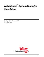
What is a <strong>Firebox</strong>?Placing a <strong>Firebox</strong> within a networkThe most common location for a <strong>Firebox</strong> is directly behind the Internet router, aspictured below:InternetThe Security ChallengeRouterEvent Processor<strong>Firebox</strong> IIManagementStationTrusted NetworkOptional NetworkSMTP ServerHTTP ServerFTP ServerOther parts of the network are as follows:Management StationThe computer on which you install and run the <strong>WatchGuard</strong> LiveSecurity ControlCenter.Event ProcessorThe computer that receives and stores log messages and sends alerts andnotifications. You can configure the Management Station to also serve as the EventProcessor.Trusted networkThe network behind the firewall that must be protected from the securitychallenge.External networkThe network presenting the security challenge, typically the Internet.Optional networkA network protected by the firewall but still accessible from the trusted and theexternal networks. Typically, the optional network is used for public servers suchas an FTP or Web server.22
Opening a configuration fileOpening a configuration filePolicy Manager is a comprehensive software tool for creating, modifying, and savingconfiguration files. A configuration file, with the extension .cfg, contains all thesettings, options, addresses, and information that together constitute your <strong>Firebox</strong>security policy. You can open and edit a configuration file residing on either yourlocal hard disk or in the primary area of the <strong>Firebox</strong> flash disk. From Policy Manager:1 Select Start => Programs => <strong>WatchGuard</strong> => Control Center.2 If you are prompted to run the Quick Setup wizard, click Continue.3 If you are prompted to connect to the <strong>Firebox</strong>, click Cancel.4 From within the <strong>WatchGuard</strong> Control Center (or <strong>WatchGuard</strong> VPNManager if you purchased this option), click the Policy Manager icon(shown at right).Opening a configuration from the <strong>Firebox</strong>From Policy Manager in the Advanced view:1 Click File => Open => <strong>Firebox</strong>.2 Use the <strong>Firebox</strong> drop list to select a <strong>Firebox</strong>.You can also type the IP address or DNS name of the <strong>Firebox</strong>.3 In the Passphrase text box, type the <strong>Firebox</strong> monitoring passphrase. Click OK.You can use either the monitoring (read-only) or configuration (read-write) passphrase. However,to save the configuration to the <strong>Firebox</strong> you must use the configuration passphrase. Theconfiguration file stored on the primary area of the <strong>Firebox</strong> flash disk opens, and configuredservices appear in the Services Arena.Opening a configuration from a local hard diskFrom Policy Manager in the Advanced View:1 Select File => Open => Configuration File.To bring up the Advanced view of Policy Manager, select View => Advanced. A checkmark willappear next to the menu option.2 Locate and select the configuration file to open. Click Open.The configuration file opens and configured services appear in the Services Arena.Saving a configuration fileAfter making changes to a configuration file, you must save it to a local hard disk.When you save a new configuration directly to a <strong>Firebox</strong>, Policy Manager promptsyou to restart that <strong>Firebox</strong> so that it will use the new configuration. The new policy isnot active until the <strong>Firebox</strong> finishes rebooting. Some tasks, such as adding new<strong>Firebox</strong> users and changing certain IPSec settings, do not require a restart in order totake effect.VPN Manager <strong>Guide</strong> 23
Resetting <strong>Firebox</strong> passphrasesSaving a configuration to the local hard diskFrom Policy Manager in the Advanced view:1 Select File => Save => As File.The Save dialog box appears.2 Enter the name of the file.The default is to save the file to the <strong>WatchGuard</strong> directory.3 Click Save.The configuration file is saved to the local hard disk.Saving a configuration to the <strong>Firebox</strong>From Policy Manager in the Advanced view:1 Select File => Save => To <strong>Firebox</strong>.2 Use the <strong>Firebox</strong> drop list to select a <strong>Firebox</strong>.3 Enter the configuration (read-write) passphrase. Click OK.The configuration file is saved first to the local hard disk and then to the primary area of the<strong>Firebox</strong> flash disk. You are prompted to restart the <strong>Firebox</strong>. The new <strong>Firebox</strong> configuration willnot be enabled until the <strong>Firebox</strong> is restarted.4 If you entered the IP address of a different <strong>Firebox</strong>, you are asked to confirm yourchoice. Click Yes.Resetting <strong>Firebox</strong> passphrases<strong>WatchGuard</strong> recommends that for optimum security you periodically change the<strong>Firebox</strong> passphrases. To do this, you must have the current configuration passphrase.From Policy Manager:1 Open the configuration file running on the <strong>Firebox</strong>.For more information, see “Opening a configuration from the <strong>Firebox</strong>” on page 23.2 Select File => Save => To <strong>Firebox</strong>.3 Use the <strong>Firebox</strong> drop list to select a <strong>Firebox</strong>. Enter the configuration passphrase.Click OK.4 Enable the Save To <strong>Firebox</strong> checkbox. Select Save Configuration File and NewFlash Image. Click Continue.5 Enter the new monitoring (read-only) and configuration (read-write) passphrases.Click OK.The new image, including the new passphrases, is saved to the <strong>Firebox</strong>, and the <strong>Firebox</strong>automatically restarts.Make certain that your monitoring and configuration passphrases are different from one another.Tips for creating secure passphrasesAlthough an attacker could crack any passphrase eventually, you can toughen yourpassphrases using the following tips:• Don’t use words in standard dictionaries, even if you use them backward or in aforeign language. Create your own acronyms instead.• Don’t use proper names, especially company names or those of famous people.24
Setting the time zone• Use a combination of uppercase and lowercase characters, numerals, and specialcharacters (such as Im4e@tiN9).Setting the time zoneThe <strong>Firebox</strong> time zone determines the date and time stamp that appear on logs andthat are displayed by services such as LogViewer, Historical Reports, andWebBlocker. Use the time zone to view log information in local time. The default timezone is Greenwich Mean Time (Coordinated Universal Time).From Policy Manager in the Advanced view:1 Select Setup => Time Zone.2 Use the drop list to select a time zone. Click OK.Check the drop list carefully. <strong>WatchGuard</strong> provides a comprehensive list of time zones toaccommodate areas in the same general time zone that follow different rules regarding theobservance and/or onset and rollback of Daylight Saving Time, and other timekeeping details.Reinitializing a misconfigured <strong>Firebox</strong>The <strong>Firebox</strong> can boot from the primary area of the flash disk (Sys A) in a mode thatprovides fail-safe access in cases when you need to:• Install a <strong>Firebox</strong> for the first time• Troubleshoot problems in which all access to the <strong>Firebox</strong> is lost• Reset <strong>Firebox</strong> passwords when you do not know or have forgotten themThis Enhanced <strong>System</strong> Mode is the default mode for new <strong>Firebox</strong>es shipped from thefactory. If a <strong>Firebox</strong> is in this mode, its Sys A light blinks. A <strong>Firebox</strong> can also be placedinto Enhanced <strong>System</strong> Mode by connecting any two of the <strong>Firebox</strong> Ethernet interfacesin a loopback configuration. Use a red crossover cable included with the <strong>Firebox</strong> forthis purpose.To access a <strong>Firebox</strong> in Enhanced <strong>System</strong> Mode:1 Establish a physical Ethernet connection between the Trusted interface of the<strong>Firebox</strong> and the Management Station on the same segment.2 Attach the red crossover cable between the remaining two <strong>Firebox</strong> interfaces, andthen turn the power on the <strong>Firebox</strong> off and then on. If a small, “factory default”switch is present on the rear of the <strong>Firebox</strong>, press and hold that switch while youturn the <strong>Firebox</strong> power off and then on.The <strong>Firebox</strong> boots into the Enhanced <strong>System</strong> Mode. This is indicated by a blinking Sys A light.3 Reinitialize the <strong>Firebox</strong> using the QuickSetup wizard.For more information on the QuickSetup wizard, see the Install <strong>Guide</strong>.4 When you complete the QuickSetup wizard, remove the loopback cable (assumingyour <strong>Firebox</strong> has one) and return the <strong>Firebox</strong> to its regular position in yournetwork. The <strong>Firebox</strong> resumes normal operation the next time it restarts.Some <strong>Firebox</strong>es have a factory default button. To place the unit into factory defaultmode, press and hold this button during power-upVPN Manager <strong>Guide</strong> 25
Reinitializing a misconfigured <strong>Firebox</strong>Booting from the system areaYou can also use the Flash Disk Management Tool to boot into the system area (Sys B)for recovery of a <strong>Firebox</strong>. For information on using the Flash Disk Management Tool,see the Reference <strong>Guide</strong>.26
CHAPTER 5Using the <strong>WatchGuard</strong>Control CenterThe <strong>WatchGuard</strong> Control Center combines access to <strong>WatchGuard</strong> <strong>Firebox</strong> <strong>System</strong>applications and tools in one intuitive interface. The Control Center also displays areal-time monitor of traffic through the firewall, connection status, tunnel status, andrecent log activity.Navigating the <strong>WatchGuard</strong> Control CenterYou interact with the Control Center using the Quick<strong>Guide</strong> toolbar and menu system.Starting the Control Center and connecting to a <strong>Firebox</strong>From the Windows Desktop:1 Select Start => Programs => <strong>WatchGuard</strong> => Control Center.2 Click Continue.3 Use the <strong>Firebox</strong> drop list to select a <strong>Firebox</strong>.You can also type the <strong>Firebox</strong> name or IP address.4 Enter the <strong>Firebox</strong> monitoring (read-only) passphrase.5 Click OK.Control Center componentsThe Control Center consists of:• A Quick<strong>Guide</strong> toolbar to invoke configuring, monitoring, and report programs• A duplication of the <strong>Firebox</strong> front panel that graphically displays traffic flow andrejected packets• <strong>Firebox</strong> and VPN tunnel status• A real-time monitor of traffic through the <strong>Firebox</strong>.<strong>User</strong> <strong>Guide</strong> 27
Control Center componentsQuick<strong>Guide</strong>The top part of the display just below the title bar is the Quick<strong>Guide</strong>. It containsbuttons to:• Open the <strong>WatchGuard</strong> Control Center menu• Pause the display• Launch Policy Manager• Launch <strong>Firebox</strong> Monitors• Launch LogViewer• Create Historical Reports• Change the dimensions of the <strong>Firebox</strong> and Tunnel Status windowFront panelUnder the toolbar is a representation of the front panel of the <strong>Firebox</strong>, including theSecurity Triangle Display, Traffic Volume Indicator, Processor Load Indicator, andbasic status information.The lights on the display represent those found on the front panel of the <strong>Firebox</strong>. Thetriangle shows the predominant flows of traffic among the Trusted, External, andOptional interfaces. A red corner of the triangle lights when that interface is blockingpackets. The two bar graphs indicate traffic volume and the proportion of <strong>Firebox</strong>capacity being used.<strong>Firebox</strong> and VPN tunnel statusThe section in the Control Center directly below the front panel shows the currentstatus of the <strong>Firebox</strong> and of Branch Office VPN tunnels and Remote VPN tunnels.<strong>Firebox</strong> statusIn <strong>Firebox</strong> status, three branches show the traffic being sent and received through thethree <strong>Firebox</strong> interfaces – Trusted, External, and Optional. Specifically, the statusbox provides the MAC (network Ethernet card) address of each interface, and thenumber of packets sent and received since the last time the <strong>Firebox</strong> rebooted.High Availability hostIf the High Availability option is installed, the first entry within the <strong>Firebox</strong> Statustree is High Availability host. When properly configured and operational, the IPaddress of the standby box appears. If High Availability is installed but the secondary<strong>Firebox</strong> is not responding, the display indicates “Not Responding.”Branch office VPN tunnelsBeneath <strong>Firebox</strong> status is a branch for branch office VPN tunnels, in which threecategories of branch office VPN tunnels appear:• IPSec• DVCP• <strong>WatchGuard</strong> VPN28
Control Center componentsThe first line of the tunnel entry shows the name that was assigned when the tunnelwas created, along with the tunnel type (IPSec, DVCP, or <strong>WatchGuard</strong>). If the tunnelis an IPSec or DVCP tunnel, it also shows the IP address of the destination IPSecdevice (such as another <strong>Firebox</strong>, SOHO, or SOHO|tc). If the tunnel is DVCP, the IPaddress refers to the entire remote network address rather than that of the <strong>Firebox</strong> orequivalent IPSec device.The next two lines display the amount of data sent and received on that tunnel inboth bytes and packets.If the tunnel is IPSec or DVCP, the lines below the packet quantities show when thekey expires and the tunnel is renegotiated. Expiration can be expressed in bytespassed or time deadline. DVCP tunnels that have been configured for both traffic andtime deadline expiration thresholds display both; this type of tunnel expires wheneither event occurs first (time runs out or bytes are passed). These lines below thepacket quantities also show the authentication and encryption levels set for thattunnel.If the tunnel is using <strong>WatchGuard</strong> VPN, the tunnel displays the packet statistics only.Remote VPN tunnelsFollowing the branch office VPN tunnels is an entry for remote VPN tunnels. RemoteVPN tunnels can either be Mobile <strong>User</strong> VPN (with IPSec) or Remote <strong>User</strong> PPTP.If the tunnel is Mobile <strong>User</strong> VPN, the branch displays the same statistics as for theDVCP or IPSec Branch Office VPN as described previously. The tunnel shows thetunnel name, followed by the destination IP address, followed by the tunnel type.Below are the packet statistics, followed by the key expiration, authentication, andencryption specifications.If the remote VPN tunnel is PPTP, then the display shows only the quantity of sentand received packets. Byte count and total byte count are not applicable to PPTPtunnel types.Expanding and collapsing the displayTo expand a branch of the display, click the plus sign (+) next to the entry, or doubleclickthe name of the entry. To collapse a branch, click the minus sign (—) next to theentry. A lack of either a plus or minus sign indicates that there is no furtherinformation about the entry.Red exclamation pointA red exclamation point appearing next to any item indicates that something withinits branch is not functioning properly. For example, a red exclamation point next tothe <strong>Firebox</strong> entry indicates that a <strong>Firebox</strong> is not communicating with either theLiveSecurity Event Processor or Management Station. A red exclamation point nextto a tunnel listing indicates a tunnel is down.When you expand an entry that has a red exclamation point, another exclamationpoint appears next to the specific device or tunnel with the problem. Use this featureto rapidly identify and locate problems with your VPN network.<strong>User</strong> <strong>Guide</strong> 29
Working with the Control CenterTraffic MonitorThe Traffic Monitor shows, in real time, the traffic through the <strong>Firebox</strong>.Working with the Control CenterThe basic tasks you perform with the Control Center are connecting to a <strong>Firebox</strong>,changing the interval at which the <strong>Firebox</strong> is queried for status information, andopening other <strong>Firebox</strong> <strong>System</strong> applications. You can also move and work with theTraffic Monitor display to best suit your needs.Connecting to a <strong>Firebox</strong>When launched, the Control Center automatically prompts you to connect to the last<strong>Firebox</strong> with which it established a connection. However, you may need to establish aconnection with another <strong>Firebox</strong>. From the Control Center:1 Click the <strong>WatchGuard</strong> Control Center button (shown at right), whichis located on the upper-left corner of Control Center. Select Connect.The Connect to <strong>Firebox</strong> dialog box appears.2 Use the <strong>Firebox</strong> drop list to select a <strong>Firebox</strong>.You can also type the <strong>Firebox</strong> name or IP address.3 Enter the <strong>Firebox</strong> monitoring (read-only) passphrase.4 Click OK.The Control Center connects to the <strong>Firebox</strong> and displays its real-time status.Changing the polling rateYou can change the interval of time (in seconds) at which the Control Center polls the<strong>Firebox</strong> and updates the Front Panel and <strong>Firebox</strong> and Tunnel Status displays.Consider, however, the trade-off between polling frequency and demand on the<strong>Firebox</strong>. The shorter the interval, the more accurate the display, but also the moredemand made of the <strong>Firebox</strong>. From the Control Center:1 Click the <strong>WatchGuard</strong> Control Center button. Click Settings.2 Type or use the scroll control to change the polling rate. Click OK.Setting the maximum number of log messagesYou can change the maximum number of status Syslog messages that are stored andviewable in Traffic Monitor. After the maximum is reached, the earliest logs areremoved as more come in. A high value in this field places a large demand on yoursystem if you have a slow processor or a limited amount of RAM. Log Viewer is amuch more appropriate tool for tracking logs; Traffic Monitor just provides a realtimeview of what the <strong>Firebox</strong> activity.1 Click the <strong>WatchGuard</strong> Control Center button. Click Settings.2 Type or use the scroll control to change the Max Log Entries field. Click OK.The value entered represents the number of logs in thousands. If you enter 0 in this field, themaximum number of logs (100,000) is permitted.30
Policy ManagerManipulating the Traffic MonitorYou can move and manipulate the Traffic Monitor on the Desktop independent of therest of the Control Center:Tear OffPoint to the Traffic Monitor title bar. Drag the Traffic Monitor to a new location onthe Desktop. To reattach the Traffic Monitor to the Control Center, drag the TrafficMonitor to the immediate vicinity of the Control Center display. The TrafficMonitor window automatically snaps back onto the Control Center.ExpandPoint to an edge of the Traffic Monitor window. Drag the edge outward to expandthe window or inward to shrink it.ScrollUse the scroll control of the Traffic Monitor window to scroll chronologically upand down through log records. While scrolling, the Traffic Monitor temporarilyceases to jump to the most recent records. Page down to the bottom of the TrafficMonitor window to restart the rolling display.Copy and PasteUse Click/Ctrl-Click or Click/Shift-Click to select multiple records. Right-click theselected records, and select Copy. Paste the selected records into anotherapplication such as e-mail, word processing, or a spreadsheet.Opening <strong>WatchGuard</strong> <strong>Firebox</strong> <strong>System</strong> toolsTo open a <strong>WatchGuard</strong> <strong>Firebox</strong> <strong>System</strong> application such as Policy Manager orHostWatch, either click the application button on the Quick<strong>Guide</strong> or click the<strong>WatchGuard</strong> Control Center button, select Tools, and then select the tool name.Policy ManagerUse the <strong>WatchGuard</strong> Policy Manager tool to design, configure, andmanage the network security policy. Within Policy Manager, you canconfigure networks and services, set up virtual private networking,regulate incoming and outgoing access, and control logging andnotification. To open Policy Manager, click the Policy Manager button(pictured at left) on the Control Center Quick<strong>Guide</strong>. Policy Manager opens anddisplays the Services Arena.The Policy Manager display includes:Pull-down menusMenus that provide access to most configuration and administration tasks.ToolbarA row of buttons immediately below the pull-down menus. Each buttoncorresponds to a frequently performed Policy Manager task. Position the mouseover the button to view a tooltip and explanatory status bar text.<strong>User</strong> <strong>Guide</strong> 31
<strong>Firebox</strong> MonitorsServices ArenaA large, open panel that displays icons to represent each network service. Doubleclickan icon to display the Properties dialog box, where you configure accesscontrols and logging for that service.Changing the Policy Manager viewPolicy Manager includes two view options: Basic and Advanced. The Advanced viewdisplays less frequently used commands. To toggle between the Policy Manager Basicand Advanced views, select View => Advanced.Service icons beginning with “wg_” are created automatically when you enablefeatures such as PPTP and authentication. These icons appear only in the Advancedview. The “wg_” service icons rarely require modification. <strong>WatchGuard</strong> recommendsleaving “wg_” icons in their default settings.Much of this <strong>User</strong> <strong>Guide</strong> is devoted to configuring and administering a networksecurity policy using Policy Manager.<strong>Firebox</strong> Monitors<strong>Firebox</strong> Monitors combines an extensive set of <strong>WatchGuard</strong> monitoringtools into a single user interface accessible from the Control Center. Toopen <strong>Firebox</strong> Monitors, click the <strong>Firebox</strong> Monitors button (pictured atleft) on the Control Center Quick<strong>Guide</strong>. <strong>Firebox</strong> Monitors opens anddisplays the Bandwidth Meter tab. For more information, see “Monitoring <strong>Firebox</strong>Activity” on page 93.LogViewerThe LogViewer application displays a static view of the log file. You canfilter by type, search for keywords and fields, and print and save log datato a separate file. To launch LogViewer, click the LogViewer button(pictured at left) on the Control Center Quick<strong>Guide</strong>. For moreinformation, see “Reviewing and Working with Log Files” on page 103.HostWatchThe HostWatch application displays active connections occurring on a<strong>Firebox</strong> in real time. It can also graphically represent the connectionslisted in a log file, either playing back a previous file for review ordisplaying connections as they are added to the current log file. To openHostWatch, click the HostWatch button (pictured at left) on the Control CenterQuick<strong>Guide</strong>. For more information, see “HostWatch” on page 98.32
Historical ReportsHistorical ReportsHistorical Reports is a report-building tool that creates HTML reportsdisplaying session types, most active hosts, most used services, URLs,and other data useful in monitoring and troubleshooting your network.To open Historical Reports, click the Historical Reports button (picturedat left) on the Control Center Quick<strong>Guide</strong>. For more information, see “GeneratingReports of Network Activity” on page 109.LiveSecurity Event ProcessorThe LiveSecurity Event Processor controls logging, report schedules, andnotification. It also provides timing services for the <strong>Firebox</strong>. The EventProcessor automatically runs when you start the machine on which it isinstalled.Unlike other <strong>Firebox</strong> <strong>System</strong> applications, the Event Processor button does notappear in Control Center. To open the Event Processor, double-click the LiveSecurityEvent Processor icon (pictured above) in the Windows Desktop tray. For moreinformation, see “Setting up the LiveSecurity Event Processor” on page 73.<strong>User</strong> <strong>Guide</strong> 33
LiveSecurity Event Processor34
CHAPTER 6Configuring a NetworkConfiguring a network refers to setting up the three <strong>Firebox</strong> interfaces. To do this,you need to:• Enter the IP address or addresses for the <strong>Firebox</strong> interfaces.• Enter the IP addresses of secondary networks that are connected to and associatedwith a <strong>Firebox</strong> interface.• Enter the default gateway for the <strong>Firebox</strong>.Use Policy Manager to configure parameters for the three <strong>Firebox</strong> interfaces–Trusted, External, and Optional.TrustedModify settings for the Ethernet device connecting the <strong>Firebox</strong> to the protectedLAN or other host.ExternalModify settings for the Ethernet device connecting the <strong>Firebox</strong> to the outsideworld.OptionalModify settings for the Ethernet device connecting the <strong>Firebox</strong> to the optionalbastion network (this is sometimes called the “Demilitarized Zone,” or “DMZ”).As its name implies, you can use the Optional network in different ways. Onecommon application is to use it for a public Web server.Running the QuickSetup wizardDuring the installation of the <strong>WatchGuard</strong> <strong>Firebox</strong> <strong>System</strong>, you are prompted to runthe QuickSetup wizard. The QuickSetup wizard creates a basic configuration file andsaves it to the primary area (Sys A) of the <strong>Firebox</strong> flash disk. The <strong>Firebox</strong> loads theprimary configuration file when it boots.<strong>User</strong> <strong>Guide</strong> 35
Setting up a drop-in networkThe QuickSetup wizard also writes a basic configuration file calledwizard.cfg to the hard disk of the Management Station. If you later want to expandor change the basic <strong>Firebox</strong> configuration using Policy Manager, use wizard.cfg asthe base file to which you make changes.You can run the QuickSetup wizard again at any time to a create new, basicconfiguration file.The QuickSetup wizard replaces the configuration file, writing over any priorversion. To make a backup copy of the configuration file on the flash disk, seethe <strong>Firebox</strong> <strong>System</strong> Area chapter in the Reference <strong>Guide</strong>.To run the QuickSetup wizard:1 Complete the Network Configuration Worksheet.A copy is included with the Install <strong>Guide</strong>. It can also be found as a .pdf file in the <strong>WatchGuard</strong>Documentation directory.2 From the Windows Desktop, select Start => Programs => <strong>WatchGuard</strong> =>QuickSetup Wizard.You can also, from the Control Center, select LiveSecurity => QuickSetup Wizard. TheQuickSetup wizard prompts for information about your network and security policy preferences.Documentation for running the QuickSetup wizard is contained in thewizard’s on-panel instructions, Install <strong>Guide</strong>, and Online Help.When the wizard prompts you to enter monitoring (read-only) andconfiguration (read-write) passphrases, use two completely differentpassphrases.Setting up a drop-in networkA drop-in network configuration is useful for situations where you can distributenetwork address space across the <strong>Firebox</strong> interfaces. In a drop-in configuration, youplace the <strong>Firebox</strong> physically between the router and the LAN, without reconfiguringany of the machines on the Trusted interface.Characteristics of a drop-in configuration:• A single network that is not subdivided into smaller networks; the network is notsubnetted.• <strong>WatchGuard</strong> performs proxy ARP.- The <strong>Firebox</strong> answers ARP requests for machines that cannot hear thebroadcasts.- The <strong>Firebox</strong> can be placed in a network without changing default gateways onthe Trusted hosts. This is because the <strong>Firebox</strong> answers for the router, eventhough the router cannot hear the Trusted host’s ARP requests.- To enable proxy ARP, you must assign the same IP address to all threeinterfaces for the <strong>Firebox</strong>. This is the only supported address assignment indrop-in configuration.• All Trusted computers must have their ARP caches flushed.• The Trusted interface ARP address replaces the router’s ARP address.36
Setting up a routed network• All three <strong>Firebox</strong> interfaces are assigned the same IP address. This is true whetheror not you use the Optional interface.• The majority of a LAN resides on the Trusted interface.• You can have other networks in other address ranges behind the <strong>Firebox</strong> usingsecondary networks. List the IP address of secondary networks in theconfiguration file.Use the sample network configuration and the Network Configuration Worksheet(found in the Install <strong>Guide</strong>) to design your drop-in network. Then either run theQuickSetup wizard to create a new configuration file or manually modify an existingconfiguration file using Policy Manager. To set up a drop-in network, from PolicyManager:1 Select Network => Configuration. Click the Drop-In Configuration tab.2 Enable the Automatic checkbox if you want the <strong>Firebox</strong> to use proxy ARP for allhosts. Disable the checkbox if you want the <strong>Firebox</strong> to use proxy ARP only onbehalf of all hists on the network you specify with the Default Network dropdownmenu.When automatic mode is enabled, the Hosts list is useful to lock a host to the specified interface.To add specific hosts that the <strong>Firebox</strong> should use proxy ARP for, enter the IP address and theinterface they reside on in the Hosts section of the Drop-In Configuration tab.3 Click Add to add a new host. To remove a host, select it and click Remove.4 When you are done setting up your network, click OK.Setting up a routed networkUse a routed network configuration when the <strong>Firebox</strong> is put in place with separatelogical networks on its interfaces. This configuration assigns separate networkaddresses to at least two of the three <strong>Firebox</strong> interfaces.If you have two separate network addresses and you want to use the routedconfiguration, use only the External and Trusted interfaces (not the Optionalinterface). Each interface must be on a separate network in routed configurationmode.If you have three or more network addresses, use the routed network configurationand map a network to each interface. Add more networks as secondary networks toone of the interfaces. You can relate different networks to different interfaces. Thosenetworks then come under the protection and access rules set up for that interface.The <strong>Firebox</strong> forwards packets to the various interfaces depending on how you defineand configure services in Policy Manager.Use the sample network configuration and the Network Configuration Worksheet(found in the Install <strong>Guide</strong>) to design your routed network. Then either run theQuickSetup wizard to create a new configuration file or manually modify an existingconfiguration file.<strong>User</strong> <strong>Guide</strong> 37
Adding a secondary networkAdding a secondary networkA secondary network is a network on the same physical wire as a <strong>Firebox</strong> interfacethat has an address belonging to an entirely different network. Adding a secondarynetwork to a <strong>Firebox</strong> interface maps an IP address from the secondary network to theIP address of the interface. This process is also known as adding an IP alias to the<strong>Firebox</strong> interface.The secondary network IP address becomes the default gateway for all the machineson that network. Adding the secondary network also tells the <strong>Firebox</strong> that anothernetwork resides on the wire.The Policy Manager does not verify that you have entered the correct address.Check secondary network addresses carefully. For example, <strong>WatchGuard</strong>recommends that you not enter a subnet on one interface that is part of alarger network on another interface.The procedure for adding a network route to all three of the <strong>Firebox</strong> interfaces isidentical. The description below is for a secondary network on the Optional interface.From Policy Manager:1 Select Network => Configuration.2 Click the Optional tab.3 In the Secondary Networks section of the dialog box, enter the network address inslash notation in the text box to the left of the Add button. Click Add.The address appears in the Secondary Networks list.Defining a network routeIf you have router behind the <strong>Firebox</strong>, you need to define a network route. FromPolicy Manager:1 Verify that you are using the Advanced view of Policy Manager.From Policy Manager, select View. Verify that the Advanced menu item has a checkmark in thebox in front of it. If it doesn’t, click it.2 Select Network => Routes.3 Click Add.4 Enter the network address in slash notation.5 In the Gateway text box, enter the route gateway.Be sure to specify a route IP address that is on the same network as the <strong>Firebox</strong>.6 Click OK.The Setup Routes dialog box lists the newly configured network route.7 Click OK.The route data is written to the configuration file.38
Defining a host routeDefining a host routeConfigure a host route if there is only one host behind the router. Enter the IP addressof that single, specific host, and do not enter a bitmask. From Policy Manager in theAdvanced view:1 Select Network => Routes.The Setup Routes dialog box appears.2 Click Add.The Add Route dialog box appears.3 Click the Host option.4 Enter the host IP address.5 In the Gateway text box, enter the route gateway.Be sure to specify a route IP address that is on the same network as the <strong>Firebox</strong>.6 Click OK.The Setup Routes dialog box lists the newly configured host route.7 Click OK.The route data is written to the configuration file.Changing an interface IP addressThe IP addresses of the three <strong>Firebox</strong> interfaces are generally configured using theQuickSetup Wizard. However, if you need to modify an interface address, you can doso manually. From Policy Manager:1 Select Network => Configuration.The Network Configuration dialog box appears.2 Click the tab of the interface requiring modification.3 In the IP Address text box, type the interface address in slash notation.Setting the default gatewayThe default gateway is generally configured using the QuickSetup Wizard. However,if you need to modify the default gateway, you can do so manually. From PolicyManager:1 Select Network => Default Gateway.2 Enter the IP address of the default gateway.3 Click OK.Entering WINS and DNS server addressesSeveral advanced features of the <strong>Firebox</strong>, such as DHCP and Remote <strong>User</strong> VPN, relyon shared Windows Internet Name Server (WINS) and Domain Name <strong>System</strong> (DNS)server addresses. These servers must be accessible from the <strong>Firebox</strong> Trusted interface.<strong>User</strong> <strong>Guide</strong> 39
Defining a <strong>Firebox</strong> as a DHCP serverFrom Policy Manager:1 Select Network => Configuration. Click the General tab.2 Enter primary and secondary addresses for the WINS and DNS servers. Enter adomain name for the DNS server.Defining a <strong>Firebox</strong> as a DHCP serverDynamic Host Configuration Protocol (DHCP) is an Internet protocol that simplifiesthe task of administering a large network. A device defined as a DHCP serverautomatically assigns IP addresses to network computers from a defined pool ofnumbers. You can now define the <strong>Firebox</strong> as a DHCP server for your network behindthe firewall.One parameter that you define for a DHCP server is lease times. This is the amount oftime a DHCP client can use an IP address that it received from the DHCP server.When the time is close to expiring, the client will contact the DHCP server to renewthe lease.From Policy Manager:1 Select Network => Configuration. Click the DHCP Server tab.2 Enable the Enable DHCP Server checkbox.3 Enter the default lease time for the server.The default lease time is provided to clients who don’t specifically request times.4 Enter the maximum lease time.The maximum lease time is the longest time the server will provide for a client. If a clientrequests a longer time, the request is denied and the maximum lease time is provided.Adding a new subnetTo increase the number of available (private) IP addresses available to DHCP clients,add a subnet. To add a new subnet, you specify a range of IP addresses to be assignedto clients on the network. For example, you could define the address range from10.1.1.100 to 10.1.1.19. This gives clients a pool of 10 addresses. From Policy Manager:1 Select Network => Configuration. Click the DHCP Server tab.2 Click Add.3 Enter a name for the subnet.4 Define the address pool by entering values for Starting IP address and Ending IPaddress.5 Click OK.Modifying an existing subnetFrom Policy Manager:1 Select Network => Configuration. Click the DHCP Server tab.2 Click the subnet to review or modify. Click Edit.3 When you have finished reviewing or modifying the subnet, click OK.40
Defining a <strong>Firebox</strong> as a DHCP serverRemoving a SubnetFrom Policy Manager:1 Select Network => Configuration. Click the DHCP Server tab.2 Click the subnet to remove it. Click Remove.3 Click OK.<strong>User</strong> <strong>Guide</strong> 41
Defining a <strong>Firebox</strong> as a DHCP server42
CHAPTER 7Blocking Sites and PortsMany types of network security attacks are easily identified by patterns found inpacket headers. Port space probes, address space probes, and spoofing attacks allexhibit characteristic behavior that a good firewall can recognize and protect against.<strong>WatchGuard</strong> allows both manual and dynamic blocking of ports and sites, and usesdefault packet-handling options to automatically and temporarily block hosts thatoriginate probes and attacks. Logging options can assist you in identifying suspectsites that repeatedly exhibit suspicious behavior. You can then manually andpermanently block a suspect site. In addition, you can protect ports with knownvulnerabilities by blocking their unauthorized use.Configuring default packet handlingThe <strong>WatchGuard</strong> <strong>Firebox</strong> <strong>System</strong> examines and handles packets according to defaultpacket-handling options that you set. The firewall examines the source of the packetand its intended destination by IP address and port number. It also watches forpatterns in successive packets that indicate unauthorized attempts to access thenetwork.The default packet-handling configuration determines whether and how the firewallhandles incoming communications that appear to be attacks on a network. Packethandling can:• Reject potentially threatening packets• Automatically block all communication from a source site• Add an event to the log• Send notification of potential security threatsFrom Policy Manager in the Advanced view:1 Select Setup => Default Packet Handling.<strong>User</strong> <strong>Guide</strong> 43
Blocking a site permanently2 Modify the default packet-handling properties according to your security policypreferences.For a description of each control, right-click the control, and then click What’s This?3 Click OK.Blocking a site permanentlyThe <strong>WatchGuard</strong> auto-blocking and logging mechanisms help you decide which sitesto permanently block.Use Policy Manager to block a site permanently. The default configuration blocksthree network addresses – 10.0.0.0/8, 172.16.0.0/12, and 192.168.0.0/16. These arethe “unconnected” network addresses. Because they are for private use, backbonerouters should never pass traffic with these addresses in the source or destinationfield of an IP packet. Traffic from one of these addresses is almost certainly a spoofedor otherwise suspect address. RFCs 1918, 1627, and 1597 cover the use of theseaddresses.The Blocked Sites list applies only to traffic on the External interface.Connections between the Trusted and Optional interfaces are not subject tothe Blocked Sites list.From the Policy Manager:1 On the toolbar, click the Blocked Sites icon.You can also select Setup => Blocked Sites. The Blocked Sites dialog box appears.2 Click Add.3 Use the Choose Type drop list to select a member type.4 Enter the member value.Depending on the member type, the value can be an IP address, host name, or username.5 Click OK.The Blocked Sites dialog box appears, displaying the new member in the Blocked Sites list.Removing a blocked siteFrom the Blocked Sites dialog box, select the site to remove, and then click Remove.Changing the auto-block durationFrom the Blocked Sites dialog box, either type or use the scroll control to change theduration, in minutes, that the firewall automatically blocks suspect sites. Durationcan range from 1 to 32,767 minutes (about 22 days).Creating exceptions to the Blocked Sites listFrom Policy Manager:1 Select Setup => Blocked Sites Exceptions.The Blocked Sites Exceptions dialog box appears.2 Click Add.44
Blocking a port permanently3 In the Choose Type field, select the address type or range.4 In Value, enter the IP address of the site for which you want to create anexception. Click OK.If you are entering a range, enter the lower value in the top box and the higher value in thebottom box.5 Click OK to close the Blocked Sites Exceptions dialog box.To remove an exception, select the site to remove. Click Remove.Logging and notification for blocked sitesFrom the Blocked Sites dialog box:1 Click Logging.The Logging and Notification dialog box appears.2 In the Category list, click Blocked Sites.3 Modify the logging and notification parameters according to your security policypreferences.For detailed instructions, see “Customizing logging and notification by service or option” onpage 76.Blocking a port permanentlyYou can block ports to explicitly cut off from external access certain network servicesthat are vulnerable entry points to your network. The Blocked Ports list takesprecedence over all service properties. For more information on precedence, seeChapter 8, “Configure Services.”Blocking ports can be useful in several ways:• Blocked ports provide an independent check to protect the most sensitive services.Even if another part of your security policy is misconfigured, blocked portsprovide an additional defense for the most vulnerable services.• Probes to particularly sensitive services can be logged independently.• Some TCP/IP services that use ports greater than 1024 are vulnerable to attack ifthe attacker originates the connection from an allowed well-known service lessthan 1024. Thus, these connections can be attacked by appearing to be an allowedconnection in the opposite direction. You should add the port numbers of suchservices to the Blocked Ports list.By default, Policy Manager blocks quite a few destination ports. This measureprovides convenient defaults that many administrators find sufficient. However,additional ports can be added to the Blocked Ports list. From Policy Manager:1 On the toolbar, click Blocked Ports.You can also select Setup => Blocked Ports.2 In the text box to the left of the Add button, type the port number. Click Add.The new port number appears at the bottom of the Blocked Ports list.<strong>User</strong> <strong>Guide</strong> 45
Blocking sites temporarily with service settingsRemoving a blocked portFrom the Blocked Ports dialog box, click a port number in the Blocked Ports list.Click Remove.Logging and notification for blocked portsFrom the Blocked Ports dialog box:1 Click Logging.The Logging and Notification dialog box appears.2 In the Category list, click Blocked Ports.3 Modify the logging and notification parameters according to your security policypreferences.For detailed instructions, see “Customizing logging and notification by service or option” onpage 76.Blocking sites temporarily with service settingsUse service properties to automatically and temporarily block sites when incomingtraffic attempts to use a denied service. You can use this feature to individually log,block, and monitor sites that attempt access to restricted ports on your network.Configuring a service to temporarily block sitesConfigure the service to automatically block sites that attempt to connect using adenied service. From Policy Manager:1 Double-click the service icon in the Services Arena.The Properties dialog box appears.2 Use the Incoming Service Connections Are drop list to select Enabled andDenied.3 Enable the Auto-Block Sites that Attempt to Connect Via checkbox.To change the auto-block duration, see “Changing the auto-block duration” on page 44.Viewing the Blocked Sites listUse <strong>Firebox</strong> Monitors to view sites that are automatically blocked according to aservice’s property configuration. From the Control Center:1 On the Quick<strong>Guide</strong>, click the <strong>Firebox</strong> Monitors icon.2 Click the Blocked Site List tab. (You might need to use the arrows to access thistab.)The Blocked Sites list appears.46
CHAPTER 8Configuring ServicesThe Services Arena of Policy Manager displays an icon for each configured service. Aservice represents a particular type of proxy or packet-filtering connection such asFTP, SMTP, or proxied HTTP. A symbol next to the service indicates whether theservice is configured for outgoing traffic, incoming traffic, or both. Services with nosymbol are not active.The <strong>Firebox</strong> <strong>System</strong> includes many well-known service types. You can also addunique or custom services. This feature accommodates new TCP/IP services as theyare developed.Adding an existing serviceAdd an existing, well-known service using the Services dialog box. From PolicyManager:1 On the toolbar, click the Add Services icon (it appears as a plus sign (+)).You can also select Edit => Add Service.2 Click to select a service from the list of available services.You can expand the tree to display all available services. When you click a service, the serviceicon appears in the dialog box, on the right side. Also, a Details box displays basic informationabout the service. For more information about individual services, see the “Types of Services”Appendix in the Reference <strong>Guide</strong>.3 Click Add.4 In the Comments text box, enter comments or a description of this version of theservice, to assist with identification.Comments appear under the Properties tab in the Comments field of the Properties dialog box.5 Click OK.The service’s Properties dialog box appears. For more information, see “Defining serviceproperties” on page 49.6 Click OK to close the Properties dialog box.<strong>User</strong> <strong>Guide</strong> 47
Creating a new service7 You can add multiple services to the Services Arena while the Services dialog boxis open. When you finish adding services, click Close.The Services Arena displays an icon for each service added.8 Click File => Save => To <strong>Firebox</strong> to save your changes to the <strong>Firebox</strong>. Specify thelocation and name of the new configuration file.Creating a new serviceIn addition to well-known services, you can create and add a new or custom service.From Policy Manager:1 On the toolbar, click Add Services.2 Click New.3 Enter the name of the new service.It must be a unique name not already listed under Services in the Services dialog box.4 Enter a description of the new service.The description appears in the Details section of the Services dialog box when you select theservice.5 Click Add.Use the Add Port dialog box to configure the port for the new service.6 Use the Protocol drop list to select a protocol:TCPTCP-based servicesUDPUDP-based servicesHTTPServices examined by the HTTP proxyIPFilter a service using something other than TCP (protocol number 6) or UDP(protocol 17) for the next-level protocol. Select IP to create a protocol numberservice.7 Use the Client Port drop list to select a client port:IgnoreClient ports will ignore the source port.SecureClient is dynamically allocated a port less than 1024 (for secure services such asSSH).PortClient port uses same port as listed in the Port number field of the service’s icon.ClientClient is dynamically allocated a port above 1000.48
Defining service properties8 In the Port text box, enter the well-known port number for this service.For a list of well-known services and their associated ports, see the Reference <strong>Guide</strong> or OnlineHelp.9 Click OK.Policy Manager adds the port configuration to the New Service dialog box.10 Verify that the name, description, and configuration of this service are correct.11 Click Add to configure another port for this service. Repeat the process until allports for the service are configured. When you finish, click OK.The Services dialog box appears with the new service. You can now add the custom service to theServices Arena just as you would an existing service. For more information, see “Adding anexisting service” on page 47.12 Click File => Save => To <strong>Firebox</strong> to save your changes to the <strong>Firebox</strong>. Specify thelocation and name of the new configuration file.Defining service propertiesUse the Properties dialog box to configure a service’s incoming and outgoing accessrules. Defining service properties includes:• Adding incoming hosts, networks, and users• Adding outgoing hosts, networks, and usersThe Properties dialog box for a typical service displays Incoming and Outgoing tabs.The Incoming tab defines which hosts and users outside the <strong>Firebox</strong> can use theservice to initiate sessions with your protected users and hosts. The Outgoing tabdefines which hosts and users behind the <strong>Firebox</strong> can use the service to initiatesessions with an outside host. You can make any service a one-directional filter bysetting the Connections Are drop list to Disabled.After defining service properties, you need to save your configuration file, asdescribed at the end of the previous procedures.Adding incoming service propertiesFrom Policy Manager:1 In the Services Arena, double-click the service.The Properties dialog box appears, displaying the Incoming tab.2 Use the Incoming Connections Are drop list to select Enabled and Allowed.3 To define specific external users or hosts that the service will allow in, click Addbeneath the From list.The Add Address dialog box appears. For a description, see “Adding addresses to serviceproperties” on page 50.4 To define specific destinations within the Trusted network that can receivethrough the service, click Add beneath the To list.5 To customize logging and notification for incoming traffic for this service, clickLogging. Configure logging and notification according to your security policypreferences.For a description of each control, right-click the control and then click What’s This?6 Click OK.<strong>User</strong> <strong>Guide</strong> 49
Configuring services for authenticationAdding outgoing service propertiesFrom Policy Manager:1 In the Services Arena, double-click the service. Click the Outgoing tab.The Properties dialog box displays the Outgoing properties tab.2 Use the Outgoing Connections Are drop list to select Enabled and Allowed.3 To define specific users and hosts on the Trusted network that can send packetsout through the service, click Add beneath the From list.The Add Address dialog box appears. For a description, see “Adding addresses to serviceproperties” on page 50.4 To define specific allowed external destinations for traffic through this service,click Add beneath the To list.5 To customize logging and notification for outgoing traffic for this service, clickLogging. Configure logging and notification according to your security policypreferences.For a description, see “Customizing logging and notification by service or option” on page 76.6 Click OK.Adding addresses to service propertiesBoth the Incoming and Outgoing properties include From and To lists of addresses.Use the Add Address dialog box to add a network, IP address, or specific user to theFrom or To list. From the service’s Properties dialog box:1 Click Add.2 To add a member that has already been defined, click your selection on theMembers list. Click Add.The member appears in the Selected Members and Addresses list.3 To add a new entry, click Add Other.4 Use the Choose Type drop list to select the member type.5 In the Value text box, enter the member IP address or name.6 Click OK.The member appears in the Selected Members and Addresses list.7 To view a list of users associated with a host on the Members list, select themember and then click Show <strong>User</strong>s.Working with wg_ iconsService icons beginning with “wg_” are created automatically when you enablefeatures such as PPTP and authentication. These icons appear only in the Advancedview of Policy Manager, in the Services Arena. The “wg_” service icons rarely requiremodification. <strong>WatchGuard</strong> recommends leaving “wg_” icons in their default settings.Configuring services for authenticationOne way to create effective user authentication environments is to restrict alloutgoing services to allow connections only from authenticated users.50
Modifying a serviceThe following example applies to dynamically addressed (DHCP-based) networks.1 Create a group on the Windows NT server that contains all the user accounts.2 In the Policy Manager Services Arena, double-click the Outgoing or Proxy serviceicon.The Properties dialog box appears, displaying the Filter Rules tab.3 Under Internal Hosts, click Add.The Add Address dialog box appears.4 Enter the group name you just created on the Windows NT server.5 Configure the Outgoing From lists on services in the Services Arena according toyour security policy preferences.Modifying a serviceAfter adding a service, some features and attributes can be changed while othersrequire that you delete the service and add it again. In general, you can modify anyproperty contained in the Properties dialog box. You must delete and add a newservice for any property set during the initial setup.Properties that can be modified on an existing service include:• Rule sets for incoming and outgoing traffic• Logging and notification characteristicsProperties that require deleting the service and adding it back again include:• Port configuration• Client port setting• ProtocolTo modify service properties, see “Defining service properties” on page 49 and“Customizing logging and notification by service or option” on page 76.To completely modify a service by deleting it and then adding it again, see “Deletinga service” on page 51 and“Adding an existing service” on page 47.Deleting a serviceThe Delete Service command deletes the selected service from the Services Arena.When you remove a service and save the new configuration, the <strong>Firebox</strong> deniesincoming connections to the service and stops all but default logging from the service.From Policy Manager, in the Services Arena:1 Select the service to delete.2 On the toolbar, click the Delete Service icon (it appears as an “X”).You can also select Edit => Delete. A verification alert appears.3 Click Yes.Policy Manager removes the service from the Services Arena.<strong>User</strong> <strong>Guide</strong> 51
Setting up proxy services4 Click File => Save => To <strong>Firebox</strong> to save your changes to the <strong>Firebox</strong>. Specify thelocation and name of the new configuration file.Setting up proxy servicesThe <strong>WatchGuard</strong> <strong>Firebox</strong> <strong>System</strong> uses a technology called “transparent proxies.”Transparent proxies can be employed without any special third-party or proxy-awaresoftware, and are transparent to client programs. <strong>WatchGuard</strong> has applicationspecificproxies for SMTP, FTP, and HTTP.When performing incoming, static NAT, internal hosts must point to theinternal IP address of the server, not the <strong>Firebox</strong> or public IP address.<strong>User</strong>s should have their WINS, host file, or internal DNS set to resolve tothe internal IP of the server in question. For more information, see“Configuring a service for incoming static NAT” on page 66.Configuring an SMTP proxy serviceThe SMTP proxy limits several potentially harmful aspects of e-mail. The proxy scansthe content type and content disposition headers and matches them against a userdefinablelist of known hostile signatures. E-mail containing suspect attachments isblocked and replaced with messages indicating that this action has been taken.The list of disallowed signatures can be modified from the Content Types tab in theSMTP Proxy dialog box. You do not have to reboot the <strong>Firebox</strong> when you make theseSMTP configuration changes.The proxy also automatically disables nonstandard commands such as Debug, andcan limit message size and number of recipients. If the message exceeds preset limits,the <strong>Firebox</strong> refuses the mail.The Policy Manager uses separate dialog boxes for incoming and outgoing SMTPrules. Because incoming messages pose a greater threat to your network thanoutgoing ones, the dialog box for incoming SMTP has more controls and configurableproperties.Configuring the incoming SMTP proxyUse the Incoming SMTP Proxy dialog box to set the incoming parameters of theSMTP proxy. You must already have an SMTP Proxy service icon in the ServicesArena. From the Services Arena:1 Double-click the SMTP Proxy icon to open the SMTP Proxy Properties dialog box.2 Click the Properties tab.3 Click Incoming.The Incoming SMTP Proxy dialog box appears, displaying the General tab.4 Modify general properties according to your preference.For a description of each control, right-click it, and then click What’s This?.5 To modify logging properties, click the Logging tab.52
Setting up proxy servicesSelecting content typesFrom the SMTP Proxy Properties dialog box:1 Click the Content Types tab.2 Click Add under the Content Types box.The Select MIME Type dialog box appears.3 Select a content type. Click OK.4 To create a new MIME type, click New Type. Enter the MIME type anddescription. Click OK.The new type appears at the bottom of the Content Types drop list. Repeat this process for eachcontent type. For a list of MIME content types, see the Reference <strong>Guide</strong>.Adding address patternsFrom the SMTP Proxy Properties dialog box:1 Click the Address Patterns tab.2 Use the Category drop list to select a category.3 Type the address pattern in the text box to the left of the Add button.4 Click Add.The address pattern appears at the bottom of the pattern list.Protecting your mail server against relayingHackers and spammers can use an open relay to send mail from your server. Toprevent this, disable open relay on your mail server. From the SMTP ProxyProperties dialog box:1 Click the Address Patterns tab.2 Select Allowed To from the Category drop list.3 In the text box to the left of the Add button, enter your own domain.With this setting, outside IPs can send mail only to your domain and not relay to other domains.4 Click Add.Select headers to allowFrom the SMTP Proxy Properties dialog box:1 Click the Headers tab.2 To add a new header, type the header name in the text box to the left of the Addbutton. Click Add.The new header appears at the bottom of the header list.3 To remove a header, select the header name in the header list. Click Remove.The header is removed from the header list.Configuring the outgoing SMTP proxyUse the Outgoing SMTP Proxy dialog box to set the parameters for traffic going fromyour Trusted and Optional network to the world. You must already have an SMTPProxy service icon in the Services Arena. Double-click the icon to open the service’sProperties dialog box:1 Click the Properties tab.<strong>User</strong> <strong>Guide</strong> 53
Setting up proxy services2 Click Outgoing.The Outgoing SMTP Proxy dialog box appears, displaying the General tab.3 To add a new header pattern, type the pattern name in the text box to the left of theAdd button. Click Add.4 To remove a header from the pattern list, click the header pattern. Click Remove.5 Set a time-out value in seconds.6 To modify logging properties, click the Logging tab.Add masquerading optionsSMTP masquerading converts an address pattern behind the firewall into ananonymized public address. For example, the internal address pattern might beinside.salesdept.bigcompany.com, which would be anonymized to their publicaddress bigcompany.com.1 Click the Masquerading tab.2 Enter the official domain name.This is the name you want visible to the outside world.3 In the Substitute text box, type the address patterns that are behind your firewallthat you want replaced by the official domain name.All patterns entered here appear as the official domain name outside the <strong>Firebox</strong>.4 In the Don’t Substitute text box, type the address patterns that you want to appear“as is” outside the firewall.5 Enable other masquerading properties according to your security policypreferences.Configuring an FTP proxy serviceTo enable the FTP proxy, add the FTP icon to the Services Arena. From the PolicyManager Services Arena:1 Double-click the FTP Proxy service icon to open the FTP Proxy Properties dialogbox.Outgoing FTP does not work without an FTP icon in the Services Arena totrigger the FTP proxy.2 Click the Properties tab.3 Click Settings.4 Enable FTP proxy properties according to your security policy preferences.For a description of each control, right-click it, and then click What’s This?5 Click OK.6 Click File => Save => To <strong>Firebox</strong> to save your changes to the <strong>Firebox</strong>. Specify thelocation and name of the new configuration file.Configuring an HTTP proxy serviceHyperText Transfer Protocol (HTTP) is the protocol used by the World Wide Web tomove information around the Internet. HTTP defines how messages are formatted54
Setting up proxy servicesand transmitted, and what actions Web servers and browsers take in response tocommands. For example, when you enter a URL into your browser, you are sendingan HTTP command to the Web server, directing it to find and send you the requestedWeb page.The HTTP proxy does content-based filtering on outgoing connections only, with aset of options that you can easily configure according to your own requirements. TheHTTP proxy does not process incoming connections. In addition, the HTTP proxy canserve as a content filter for Web browsers. For more information, see “Configuringthe WebBlocker service” on page 60.You can use two types of HTTP services:• Proxied-HTTP service allows outbound HTTP on TCP port 80 to be proxiedthrough the <strong>Firebox</strong>. The proxy has the capability of performing HTTP-specificcontent filtering of each connection. Such content filtering can include denying orremoving “unsafe” content types (such as Java or ActiveX) and performinggeneral verifications on the HTTP exchange.• Filtered-HTTP service allows outbound HTTP on all TCP ports, but incomingaccess only on port 80. Filtered HTTP is filtered by the standard packet filter,which can restrict access by IP address or alias only. No proxy is used with thisservice, meaning that Filtered-HTTP cannot make use of any of the advancedHTTP-specific content-filtering options provided by the proxy. You must useproxied-HTTP if you want accounting logs – for example, byte counts.With either type of HTTP service, you should have a single icon that allows forgeneral outgoing HTTP access (for most internal users) and incoming HTTP access toa limited set of Web servers.The <strong>WatchGuard</strong> service called “HTTP” is not to be confused with an HTTPcaching proxy. An HTTP caching proxy refers to a separate machine thatperforms caching of Web data.From Policy Manager:1 Double-click the HTTP Proxy service icon to open the HTTP Proxy Propertiesdialog box.2 Click the Properties tab. Click Settings.3 If you are using the HTTP proxy service because you want to use WebBlocker,follow the procedure in the next section. Otherwise, enable HTTP proxy propertiesaccording to your security policy preferences.For detailed descriptions of HTTP proxy options, see the Reference <strong>Guide</strong>.Zip files are denied when you deny Java or ActiveX applets, because zip filesoften contain these applets.4 Click the Safe Content tab.5 Add or remove properties according to your security policy preferences. Click OK.<strong>User</strong> <strong>Guide</strong> 55
Service precedenceService precedencePrecedence is generally given to the most specific service and descends to the mostgeneral service. However, exceptions exist. There are three different precedencegroups for services:• The “Any” service (see the Online Help system for information about the “Any”packet filter service). This group has the highest precedence.• IP and ICMP services and all TCP/UDP services that have a port numberspecified. This group has the second highest precedence and is the largest of thethree.• “Outgoing” services that do not specify a port number (they apply to any port).This group includes Outgoing TCP, Outgoing UDP, and Proxy.“Multiservices” can contain subservices of more than one precedence group.“Filtered-HTTP” and “Proxied-HTTP,” for example, contain both a port-specific TCPsubservice for port 80 as well as a nonport subservice that covers all other TCPconnections. When precedence is being determined, individual subservices are givenprecedence according to their group (described previously) independent of the othersubservices contained in the multiservice.Precedence is determined by group first. Services from a higher precedence groupalways have higher precedence than the services of a lower-precedence group,regardless of their individual settings (for example, the lowest precedence “Any”service will take precedence over the highest precedence Telnet service).The precedences of services that are in the same precedence group are ordered fromthe most specific services (based on source and destination targets) to the leastspecific service. The method used to sort services is based on the specificity of targets,from most specific to least specific. The following order is used:From To RankIP IP 0List IP 1IP List 2List List 3Any IP 4IP Any 5Any List 6List Any 7Any Any 8“IP” refers to exactly one host IP address; “List” refers to multiple host IP addresses, anetwork address, or an alias; and “Any” refers to the special “Any” target (not “Any”services).When two icons are representing the same service (for example, two Telnet icons ortwo Any icons) they are sorted using the above tables. The most specific one willalways be checked first for a match. If a match is not made, the next specific servicewill be checked, and so on, until either a match is made or there are no services left to56
Service precedencecheck. In the latter case, the packet is denied. For example, if there are two Telneticons, telnet_1 allowing from A to B and telnet_2 allowing from C to D, a Telnetattempt from C to E will first check telnet_1, and then telnet_2. Because no match isfound, the rest of the rules are considered. If an Outgoing service will allow from C toE, it will do so.When only one icon is representing a service in a precedence category, only thatservice is checked for a match. If the packet matches the service and both targets, theservice rule applies. If the packet matches the service but fails to match either target,the packet is denied. For example, if there is one Telnet icon allowing from A to B, aTelnet attempt from A to C will be blocked without considering any services furtherdown the precedence chain, including Outgoing services.<strong>User</strong> <strong>Guide</strong> 57
Service precedence58
CHAPTER 9Controlling Web TrafficWebBlocker is a feature of the <strong>Firebox</strong> <strong>System</strong> that works in conjunction with theHTTP proxy to provide Web-site filtering capabilities. It enables you to exert finecontrol over the type of Web sites that users on your trusted network are allowed toview.For more information about WebBlocker and site blocking, see the WebBlockersection of the Network Security Handbook.How WebBlocker worksWebBlocker relies on a URL database built and maintained by SurfControl. TheWebBlocker database contains more than 65,000 IP addresses and 40,000 directories.The database is copied to the <strong>WatchGuard</strong> WebBlocker site at regular intervals. TheEvent Processor is automatically configured to download the most recent version ofthe database from the <strong>WatchGuard</strong> WebBlocker site over an authorized channel. Inturn, the <strong>Firebox</strong> regularly queries the Event Processor for changes and, whenappropriate, downloads a new version and generates a log entry to show the transfer.If the database is either corrupted, incompletely retrieved, or in any other wayincomplete, the <strong>Firebox</strong> does not load it. It repeats the attempt until it completes asuccessful transfer.When you restart your <strong>Firebox</strong>, all Web access is blocked for a brief period of time.<strong>User</strong>s might receive the error message “Database not loaded” until the <strong>Firebox</strong>downloads a database.Reverting to old WebBlocker databasesTo revert to a previous copy of the WebBlocker database, use the files namedWebblocker.old and Webblocker.old2 found in the installation directory. Rename thefiles Webblocker.db and Weblocker.db2, respectively. The <strong>Firebox</strong> automaticallyupdates to the latest WebBlocker database the next time it queries Event Processor.<strong>User</strong> <strong>Guide</strong> 59
Configuring the WebBlocker serviceLogging and WebBlockerWebBlocker logs attempts to access sites blocked by WebBlocker. The log that isgenerated displays information about source and destination address as well as theblocked URL and the category that caused the denial.WebBlocker also generates a log entry showing the results of any attempted databaseretrieval, including whether or not it was successful and, if not successful, why.Prerequisites to using WebBlockerYou need to complete several tasks before you can configure the <strong>Firebox</strong> to useWebBlocker:• Configure the <strong>WatchGuard</strong> service iconBecause WebBlocker relies on copying updated versions of the WebBlockerdatabase to the Event Processor, you must configure the <strong>WatchGuard</strong> servicesetting Allow Outgoing to Any. It is possible to narrow this setting and use the IPaddress of webblocker.watchguard.com. However, this address may changewithout notice.• Add some form of HTTP service iconTo use WebBlocker, add the Proxied-HTTP, Proxy, or HTTP service. <strong>WatchGuard</strong>recommends using Proxied-HTTP, which provides filtering on all ports. (HTTPwithout the Proxy service blocks only on port 80.) WebBlocker takes precedenceover other settings in the HTTP or Proxy services. If the HTTP service allowsoutgoing from Any to Any but WebBlocker settings are set to “Block All URLs,” allWeb access is blocked. For information on adding an HTTP proxy service, see“Configuring an HTTP proxy service” on page 55.Configuring the WebBlocker serviceWebBlocker is a built-in feature of the service icons including HTTP, Proxied HTTP,and Proxy. When WebBlocker is installed, five tabs appear in the HTTP service icondialog box:• WebBlocker Controls• WB: Schedule• WB: Operational Hours• WB: Non-Operational Hours• WB: ExceptionsActivating WebBlockerTo start using WebBlocker, you must activate the feature. <strong>WatchGuard</strong> recommendsenabling the Auto Download option at the same time. This ensures that Event60
Configuring the WebBlocker serviceProcessor regularly and automatically updates the WebBlocker database stored onyour <strong>Firebox</strong>. From Policy Manager:1 If you have not already done so, double-click the service icon you are using forHTTP. Click the Properties tab. Click Settings.The proxy’s dialog box appears.2 Click the WebBlocker Controls tab.The WebBlocker Controls tab appears only if you selected WebBlocker during installation. If thetabs are not visible, run the installation wizard and install the WebBlocker option. For moreinformation, see the Install <strong>Guide</strong>.3 Enable the Activate WebBlocker checkbox.4 If appropriate, enable the Auto-Download the WebBlocker Database checkbox.5 Enter the message to be displayed when an end-user attempts to open a blockedWeb site.Scheduling operational and non-operational hoursWith WebBlocker, you can differentiate between operational hours and nonoperationalhours in selecting which categories to block. From the proxy’s dialog box:1 Click the WB: Schedule tab.2 Click hour blocks to toggle from Operational to Non-Operational.Setting privilegesWebBlocker differentiates URLs based on their content. Select the types of contentaccessible during operational and non-operational hours using the Privileges tabs.The options are identical for Operational and Non-Operational. From the proxy’sdialog box:1 Click the WB: Operational Privileges tab.2 Enable the content type checkboxes for the categories you would like to block.For more information on WebBlocker Categories, see the Reference <strong>Guide</strong>.Creating WebBlocker exceptionsUse exceptions to override any WebBlocker setting. Exceptions take precedence overall other rules. These blocked URLs apply only to HTTP traffic and are not related tothe Blocked Sites list.Exceptions are listed by IP address, but can be entered as domain names, networkaddresses, or host IP addresses. You can fine-tune an exception by specifying a portnumber, path, or string that is to be blocked for a particular Web site. For moreinformation on working with exceptions, see the WebBlocker section of the NetworkSecurity Handbook.From the HTTP Proxy dialog box:1 Click the WB: Exceptions tab (you might need to use the arrow keys at the right ofthe dialog box to see this tab).<strong>User</strong> <strong>Guide</strong> 61
Manually downloading the WebBlocker database2 In the Allowed Exceptions section, click Add to add either a network or host IPaddress to be allowed at all times.To allow a specific string for a domain, select Host Address. To allow a specific directory pattern,enter the string to be allowed.3 In the Deny Exceptions section, click Add to add either a network or an IP addressto be denied at all times.To block a specific string to be denied for a domain, select Host Address. To block a specificdirectory pattern, enter the string to be blocked (for example, “*poker”).4 To remove an item from either the Allow or the Deny list, click the address. Clickthe corresponding Remove button.Manually downloading the WebBlocker databaseYou can manually force a download of the latest blocked URL database fromwebblocker.watchguard.com using a DOS utility called dbfetch.1 Open an MS-DOS Prompt window.2 Change directories to the <strong>WatchGuard</strong> installation directory.3 Issue the dbfetch command. The command syntax isdbfetch [-debug] [name or IP address] [port]–debug — Outputs debugging information.name or IP address — Defaults to webblocker.watchguard.com.port — Sets port number; defaults to 4103.62
CHAPTER 10Setting Up NetworkAddress TranslationNetwork address translation (NAT) hides internal network addresses from hosts onan external network. <strong>WatchGuard</strong> supports two types of NAT:• Outgoing dynamic NATHides network addresses from hosts on another network; works only on outgoingmessages.• Incoming static NATProvides port-to-host remapping of incoming IP packets destined for a publicaddress to a single internal address; works only on incoming messages.For more information on NAT, see the Network Security Handbook.What is dynamic NAT?Also known as IP masquerading or port address translation, dynamic NAT hidesnetwork addresses from hosts on another network. Hosts elsewhere only seeoutgoing packets from the <strong>Firebox</strong> itself. This feature protects the confidentiality andarchitecture of your network. Another benefit is that it enables you to conserve IPaddresses.<strong>WatchGuard</strong> implements two forms of outgoing dynamic NAT:• Simple NAT – Using host aliases or IP host and network IP addresses, the<strong>Firebox</strong> globally applies network address translation to every outgoing packet.• Service-based NAT – Configure each service individually for outgoing dynamicNAT.Machines making incoming requests over a VPN connection are allowed toaccess masqueraded hosts.<strong>User</strong> <strong>Guide</strong> 63
Using simple dynamic NATUsing simple dynamic NATIn the majority of networks, the preferred security policy is to globally apply networkaddress translation to all outgoing packets. Simple dynamic NAT provides a quickmethod to set NAT policy for your entire network.Enabling simple dynamic NATThe default configuration of simple dynamic NAT enables it from the Trustednetwork to the External network. To enable simple dynamic NAT, use the SetupDynamic NAT dialog box. From Policy Manager:1 Select Setup => NAT.2 Enable the Enable Dynamic NAT checkbox.Adding dynamic NAT entriesUsing built-in host aliases, you can quickly configure the <strong>Firebox</strong> to masqueradeaddresses from your Trusted and Optional networks. For the majority of networks,only a single entry is necessary:• From: Trusted• To: ExternalLarger or more sophisticated networks may require additional entries in the From orTo lists of hosts, or host aliases. The <strong>Firebox</strong> applies dynamic NAT rules in the orderin which they appear in the Dynamic NAT Entries list. <strong>WatchGuard</strong> recommendsprioritizing entries based on the volume of traffic that each represents. From theSetup Dynamic NAT dialog box:1 Click Add.2 Use the From drop list to select the origin of the outgoing packets.For example, use the trusted host alias to globally enable network address translation from theTrusted network. For a definition of built-in <strong>Firebox</strong> aliases, see “Using host aliases” on page 85.For information on how to add a user-defined host alias, see “Adding a host alias” on page 86.3 Use the To drop list to select the destination of outgoing packets.4 To add either a host or network IP address, click the ... button. Use the drop list toselect the address type. Enter the IP address. Network addresses must be enteredin slash notation.5 Click OK.The new entry appears in the Dynamic NAT Entries list.Reordering dynamic NAT entriesTo reorder dynamic NAT entries, select the entry and click either Up or Down. Thereis no method to modify a dynamic NAT entry. Instead, use the Remove button toremove existing entries and the Add button to add new entries.64
Using service-based NATUsing service-based NATUsing service-based NAT, you can set outgoing dynamic NAT policy on a service-byservicebasis. Service-based NAT is most frequently used to make exceptions to aglobally applied simple dynamic NAT entry.For example, use service-based NAT on a network with simple NAT enabled fromthe Trusted to the Optional network with a Web server on the Optional network thatshould not be masqueraded to the actual Trusted network. Add a service iconallowing Web access from the Trusted to the Optional Web server, and disable NAT.In this configuration, all Web access from the trusted network to the optional Webserver is made with the true source IP, and all other traffic from Trusted to Optional ismasqueraded.You can also use service-based NAT in lieu of simple dynamic NAT. Rather thanapplying NAT rules globally to all outgoing packets, you can start from the premisethat no masquerading takes place and then selectively masquerade a few individualservices.Enabling service-based NATService-based NAT is not dependent on enabling simple dynamic NAT. From PolicyManager:1 Select Setup => NAT. Click Advanced.2 Enable the Enable Service-Based NAT checkbox.3 Click OK to close the Advanced NAT dialog box. Click OK to close the DynamicNAT dialog box.Configuring service-based NAT exceptionsBy default, services take on whatever dynamic NAT properties you have set forsimple NAT. However, you can override this setting in the service’s Properties dialogbox. There are three options:• Use Default (Simple NAT) – Service-based NAT is not enabled for the service.The service will use the simple dynamic NAT rules configured in the DynamicNAT Entries list (see “Adding dynamic NAT entries” on page 64).• Disable NAT – Disables dynamic NAT for outgoing packets using this service.Use this setting to create service-by-service exceptions to outgoing NAT.• Enable NAT – Enables service-based NAT for outgoing packets using this serviceregardless of how the simple dynamic NAT settings are configured.From Policy Manager:1 Double-click the service icon. Click Outgoing.If either simple dynamic NAT or service-based NAT is already enabled, an entry appears at thebottom of the Outgoing tab.2 Use the Choose Dynamic NAT Setup drop list to select either the default, disable,or enable setting.3 Click OK.<strong>User</strong> <strong>Guide</strong> 65
Configuring a service for incoming static NATConfiguring a service for incoming static NATStatic NAT works on a port-to-host basis. Incoming packets destined for a specificpublic address and port on the External network are remapped to an address andport behind the firewall. You must configure each service separately for static NAT.Typically, static NAT is used for public services such as Web sites and e-mail that donot require authentication.Static NAT can be used only to forward connections from the outside to an internalhost. It is not possible for hosts already behind the <strong>Firebox</strong> to use the static NAT entrywhen accessing an internal server. While hosts on the External interface of the <strong>Firebox</strong>connect to the <strong>Firebox</strong> IP address and specified port (which then forwards theconnection internally), hosts on the inside of the <strong>Firebox</strong> must connect directly to theactual, internal server IP address. This is usually only a problem when DNS isinvolved. To avoid this problem, it is best to use a private DNS server (or static DNSmapping, such as /etc/hosts for UNIX machines, or an Lmhosts file for Windowsmachines) for internal hosts. This way, internal systems that try to connect to theserver by name will always get the internal IP address.Adding external IP addressesStatic NAT converts a <strong>Firebox</strong> public IP and port into specific destinations on theTrusted or Optional networks. If the <strong>Firebox</strong> has not already been assigned the publicIP address you want to use, you must designate a new public IP address using theAdd External IP dialog box. From Policy Manager:1 Select Network => Configuration. Click the External tab.2 Click Aliases.3 At the bottom of the dialog box, enter the public IP address. Click Add.4 Repeat until all external public IP addresses are added. Click OK.Setting static NAT for a serviceStatic NAT, like service-based NAT, is configured on a service-by-service basis.Because of the way static NAT functions, it is available only for services containingTCP, UDP, FTP, SMTP, or HTTP. A service containing any other protocol cannot useincoming static NAT, and the button in the service’s Properties dialog box isdisabled.1 Double-click the service icon in the Services Arena.The service’s Properties dialog box appears, displaying the Incoming tab.2 Use the Incoming drop list to select Enabled and Allowed.To use static NAT, the service must allow incoming traffic.3 Under the To list, click Add.The Add Address dialog box appears.4 Click NAT.5 Use the External IP Address drop list to select the “public” address to be used forthis service.If the public address does not appear in the drop list, click Edit to open the Add External IPAddress dialog box.66
Configuring a service for incoming static NAT6 Enter the internal IP address.The internal IP address is the final destination on the Trusted network.7 If appropriate, enable the Set Internal Port To Different Port Than Servicecheckbox.This feature is rarely used. It enables you to redirect packets not only to a specific internal hostbut also to an alternative port. If you enable the checkbox, enter the alternative port number inthe Internal Port field.8 Click OK to close the Add Static NAT dialog box.The static NAT route appears in the Members and Addresses list.9 Click OK to close the Add Address dialog box. Click OK to close the service’sProperties dialog box.<strong>User</strong> <strong>Guide</strong> 67
Configuring a service for incoming static NAT68
CHAPTER 11Setting Up Logging andNotificationLogging and notification are crucial to an effective network security policy. Together,they make it possible to monitor your network security, identify both attacks andattackers, and take action to address security threats and challenges.Logging occurs when the firewall records the occurrence of an event to a log file.Notification occurs when the firewall sends e-mail, pops up a window on the EventProcessor, or dials a pager to notify an administrator that <strong>WatchGuard</strong> detected atriggering event.<strong>WatchGuard</strong> logging and notification features are both flexible and powerful. Youcan configure your firewall to log and notify on a wide variety of events, includingspecific events at the level of individual services.Ensure logging with failover logging<strong>WatchGuard</strong> relies on failover logging to minimize the possibility of missing logevents. With failover logging, you configure a list of Event Processors to accept logsin the event of a failure of the primary Event Processor. By default, the <strong>Firebox</strong> sendslog messages to the primary Event Processor. If for any reason the <strong>Firebox</strong> cannotestablish communication with the primary Event Processor, it automatically sends<strong>User</strong> <strong>Guide</strong> 69
<strong>WatchGuard</strong> logging architecturelog messages to the second Event Processor. It continues through the list until it findsan Event Processor capable of recording events.Multiple Event Processors operate in failover mode, not redundancymode—that is, events are not logged to multiple Event Processorssimultaneously; they are logged only to the primary Event Processor unlessthat host becomes unavailable. Then the logs are passed on to the nextavailable Event Processor according to the order of priority. As soon as ahigher-priority Event Processor becomes available again, the logs areshifted to that host. The highest-ranking Event Processor available alwaysreceives the logs.The LiveSecurity Event Processor software must be installed on each EventProcessor. For more information, see “Setting up the LiveSecurity EventProcessor” on page 73.<strong>WatchGuard</strong> logging architectureThe flexible architecture of the <strong>Firebox</strong> <strong>System</strong> makes it possible to separate thelogging and notification responsibilities to multiple machines. By default, the PolicyManager and the log and notification application – the LiveSecurity Event Processor– are installed on the same computer. You can, however, install the Event Processorsoftware on a separate or multiple computers.You must complete the following tasks to configure the firewall for logging andnotification:Policy Manager- Add logging and notification host(s)- Customize preferences for services and packet handling options- Save the configuration file with logging properties to the <strong>Firebox</strong>LiveSecurity Event Processor- Install the software on each Event Processor- Set global logging and notification preferences for the host- Set the log encryption key on the Event Processor identical to the key set inPolicy Manager.Designating Event Processors for a <strong>Firebox</strong>You should have at least one Event Processor to run the <strong>WatchGuard</strong> <strong>Firebox</strong> <strong>System</strong>.The default primary Event Processor is the Management Station, which is set whenyou run the QuickSetup wizard. You can specify a different primary Event Processoras well as multiple backup Event Processors.• IP address of each Event Processor• Encryption key to secure the connection between the <strong>Firebox</strong> and EventProcessors• Priority order of primary and backup Event Processors70
Designating Event Processors for a <strong>Firebox</strong>Adding an Event ProcessorFrom Policy Manager:1 Select Setup => Logging.2 Click Add.3 Enter the IP address to be used by the Event Processor.4 Enter the encryption key that secures the connection between the <strong>Firebox</strong> and theEvent Processor.The default encryption key is the monitoring passphrase set in the QuickSetup wizard. You mustuse the same log encryption key for both the <strong>Firebox</strong> and the LiveSecurity Event Processor.5 Click OK.Repeat until all primary and backup Event Processors appear in the LiveSecurity EventProcessors list.Enabling Syslog loggingNote that Syslog logging is not encrypted; therefore, do not set the Syslog server to ahost on the External interface. From Policy Manager:1 Select Setup => Logging.The Logging Setup dialog box appears.2 In the Logging Setup dialog box, click the Syslog tab.3 Enable the Enable Syslog Logging checkbox.4 Enter the IP address of the Syslog server.Editing an Event Processor settingModify an Event Processor entry to change the log encryption key. From PolicyManager:1 Select Setup => Logging.The Logging Setup dialog box appears.2 Click the host name. Click Edit.3 Modify the IP address or log encryption key fields. Click OK.You must use the same log encryption key for both the <strong>Firebox</strong> and the LiveSecurity EventProcessor. To change the log encryption key on the Event Processor, see “Setting the logencryption key” on page 75.Removing an Event ProcessorRemove an Event Processor when you no longer want to use it for any loggingpurpose. From Policy Manager:1 Select Setup => Logging.The Logging Setup dialog box appears.2 Click the host name. Click Remove.<strong>User</strong> <strong>Guide</strong> 71
Designating Event Processors for a <strong>Firebox</strong>3 Click OK.The Logging Setup dialog box closes and removes the Event Processor entry from theconfiguration file.If you move the Event Processor to a host on another networkand change the Event Processor’s host address on the <strong>Firebox</strong>,make sure to uninstall the Event Processor software from themachine that is no longer the Event Processor host.Reordering Event ProcessorsEvent Processor priority is determined by the order in which they appear in theLiveSecurity Event Processor(s) list. The host that is listed first receives log messages.Use the Up and Down buttons to change the order of the Event Processors. From theLogging Setup dialog box:• To move a host down, click the host name. Click Down.• To move a host up, click the host name. Click Up.Synchronizing Event ProcessorsSynchronizing Event Processors is the act of setting the clocks of all your EventProcessors to a single common time source. Synchronizing Event Processors keepslogs orderly and avoids time discrepancies in the log file if failovers occur.The <strong>Firebox</strong> sets its clock to the current Event Processor. If the <strong>Firebox</strong> and the EventProcessor time are different, the <strong>Firebox</strong> time drifts toward the new time, which oftenresults in a brief interruption in the log file. Rebooting the <strong>Firebox</strong> resets the <strong>Firebox</strong>time to that of the primary Event Processor. Therefore, you should set all EventProcessors’ clocks to a single source. In a local installation where all Event Processorsare on the same domain, set each Event Processor to the common domain controller.For Windows NT Event Processors1 Go to each Event Processor. Open an MS-DOS Command Prompt window. Typethe following command:net time /domain:domainName /setwhere domainName is the domain in which the Event Processors operate.The system returns a message naming the domain controller.2 Type Y.The time of the local host is set to that of the domain controller.Another way to set the Event Processor (and domain controller) clocks is to use anindependent source such as the atomic clock—based servers available on the Internet.One place to access this service is:http://www.bldrdoc.gov/timefreq72
Setting up the LiveSecurity Event ProcessorSetting up the LiveSecurity Event ProcessorThe LiveSecurity Event Processor controls logging and notification. It also providesscheduling services for the <strong>Firebox</strong>; if the Event Processor is not running, you may beunable to connect to the <strong>Firebox</strong>.Installing the Event Processor programThe LiveSecurity Event Processor program is separate from the <strong>WatchGuard</strong> ControlCenter and Policy Manager. It must be installed and the log encryption key enteredon all Event Processors. Although it can be installed on the Management Stationduring the QuickSetup wizard installation process, you must also install and run it onany additional Event Processors.The LiveSecurity Event Processor program is available both as a command-line utilityand, on a Windows NT host, as a service. During installation, the setup utility detectswhether or not the host is operating Windows NT or Windows 2000. If so, it installsthe program as a service that automatically starts when you restart the machine:1 Run the <strong>WatchGuard</strong> <strong>Firebox</strong> <strong>System</strong> installation wizard.2 When the wizard asks if you would like to set up logging and notification, selectYes.Running an Event Processor on Windows 98If the Event Processor is to be run on a Windows 98 operating system, it must be runfrom the command line in a DOS window or directly from the Startup folder. A DOSwindow stays open as long as the LiveSecurity Event Processor is running. If youmust log off a Windows 98 Event Processor, the program exits and logging will notwork. On the Event Processor host:1 Open a DOS window.Select Start => Programs => MS-DOS Prompt.2 Change directories to the <strong>WatchGuard</strong> installation directory.The default installation directory is C:\Program Files\<strong>WatchGuard</strong>.3 Enter the following command:controld -iThe Event Processor starts. You can minimize the DOS window. Do not, however, close thewindow. Closing the DOS window halts the Event Processor.Running an Event Processor on Windows NT or Windows 2000If the Event Processor is to be run on a Windows NT or Windows 2000 operatingsystem, there are two methods to run it: interactive mode from a DOS window or as aWindows NT service. The default method on installation is for it to run as a WindowsNT service.As a Windows NT or Windows 2000 ServiceBy default, the Event Processor is installed to run as a Windows NT service, startingautomatically every time the host computer restarts. You can also install and run theEvent Processor manually:1 At the command line, type:<strong>User</strong> <strong>Guide</strong> 73
Setting up the LiveSecurity Event Processorcontrold -nt-install2 Start the LiveSecurity Event Processor service.Select Start => Settings => Control Panel. Double-click Services. Click WG LiveSecurity EventProcessor. Click Start. You can also restart your computer. The service starts automaticallyevery time the host reboots.3 To remove the Event Processor as a service, stop it using Control Panel. Then, atthe command line, type:controld -nt-removeIn addition, if the Event Processor is running as a service and you are using pop-upnotifications, you must ensure that the service can interact with the Desktop:1 In Control Panel, double-click Services. In Windows 2000, click Start => Settings =>Control Panel => Administrative Tools => Services.2 Click WG LiveSecurity Event Processor. Click Startup.3 Verify that the Allow Service To Interact With Desktop checkbox is enabled.If the Event Processor was running, restart it after saving the changes.Interactive mode from a DOS windowOn the Event Processor:1 Open a DOS window.Select Start => Programs => Command Prompt.2 Change directories to the <strong>WatchGuard</strong> installation directory.The default installation directory is C:\Program Files\<strong>WatchGuard</strong>.3 Type the following command:controld -NT-interactiveThe Event Processor starts. You can minimize the DOS window. Do not, however, close thewindow. Closing the DOS window halts the Event Processor.Viewing the Event ProcessorWhile the LiveSecurity Event Processor is running, a <strong>Firebox</strong>-and-traffic icon appearsin the Windows Desktop tray. To view the Event Processor, right-click the tray iconand select Log Center.If the Event Processor icon is not in the tray, in the Control Center, select LiveSecurity=> Logging => Event Processor Interface. To start the Event Processor interface whenyou log in to the system, add a shortcut to the Startup folder in the Start menu. The<strong>WatchGuard</strong> installation program does this automatically if you set up logging.Starting and stopping the Event ProcessorThe Event Processor starts automatically when you start the host on which it resides.However, it is possible to stop or restart the Event Processor from its interface at anytime. Open the Event Processor interface:• To start the Event Processor, select File => Start Service.• To stop the Event Processor, select File => Stop Service.74
Setting global logging and notification preferencesSetting the log encryption keyThe log connection (but not the log file) between the <strong>Firebox</strong> and an Event Processoris encrypted for security purposes. Both the Management Station and the EventProcessor must possess the same encryption key.You must enter an encryption key in order for the Event Processor to receivelogs from the <strong>Firebox</strong>. It must be the same key used when adding an EventProcessor to the Management Station.From the LiveSecurity Event Processor:1 Select File => Set Log Encryption Key.2 Enter the log encryption key in both text boxes. Click OK.Setting global logging and notification preferencesThe LiveSecurity Event Processor lists the connected <strong>Firebox</strong> and displays its status. Ithas three control areas:• Log File tab – Specify the maximum number of records stored in the log file.• Reports tab – Schedule regular reports of log activity.• Notification tab – Control to whom and how notification takes place.Together, these controls set the general parameters for most global event processingand notification properties.Setting the interval for log rolloverLog records accumulate at different rates depending on the volume of network trafficand the logging and notification settings configured for services and properties. Youcan control when the Event Processor rolls log entries from one file to the next usingthe Log Files tab in the Event Processor. For example, configure the Event Processorto roll over from one log file to the next by time interval, number of entries, or both.From the Event Processor interface:1 Click the Log Files tab.2 For a time interval, enable the By Time Interval checkbox. Select the frequency.Use the Schedule First Log Roll For drop list to select a date. Use the scroll controlor enter the first time of day.3 For a record size, enable the By Number of Entries checkbox. Use the scroll controlor enter a number of log record entries.The Approximate Size field changes to display the approximate file size of the final log file. For adetailed description of each control, right-click it, and then select What’s This?.4 Click OK.The Event Processor Interface closes and saves your entries. New settings take effectimmediately.<strong>User</strong> <strong>Guide</strong> 75
Customizing logging and notification by service or optionScheduling log reportsYou can use the Event Processor to schedule the automatic generation of networkactivity reports. For more information, see “Scheduling a report” on page 114.Controlling notificationNotification occurs when the firewall sends an e-mail, pops up a window on theEvent Processor, or dials a pager to notify an administrator that the <strong>Firebox</strong> detected atriggering event. Use the Event Processor to control when and to whom suchnotifications are sent. From the Event Processor interface:1 Click the Notification tab.2 Modify the settings according to your security policy preferences.For more information on individual settings, right-click the setting, and then select What’s This?.Customizing logging and notification by service or optionThe <strong>Firebox</strong> <strong>System</strong> allows you to create custom logging and notification propertiesfor each service and blocking option. You can fine-tune your security policy, loggingonly those events that require your attention and limiting notification to truly highpriorityevents.To make logging and notification configuration easier, services, blocking categories,and packet-handling options share an identical dialog box. Therefore, once you learnthe controls for one type of service, you can easily configure the remainder.The Logging and Notification dialog box contains the following controls:CategoryThe event types that can be logged by the service or option. This list changesdepending on the service or option. Click the event name to display and set itsproperties.Enter it in the logEnable this checkbox to log the event type; clear it to disable logging for the eventtype. Because the <strong>Firebox</strong> must perform domain name resolution, there may be atime lag before logs appear in the log file. All denied packets are logged by default.Send NotificationEnable this checkbox to enable notification on the event type; clear it to disablelogging for the event type.The remaining controls are active when you enable the Send Notification checkbox:E-mailTriggers an e-mail message when the event occurs. Set the e-mail recipient in theNotification tab of the LiveSecurity Event Processor.PagerTriggers a page when the event occurs. Set the pager number in the Notificationtab of the LiveSecurity Event Processor.76
Customizing logging and notification by service or optionPopup WindowTriggers a pop-up window display on the Event Processor when the event occurs.Custom ProgramTriggers a custom program when the event occurs. <strong>WatchGuard</strong> allows only onenotification type per event. A custom batch file or program enables you to triggermultiple types of notification. Type the full path to the program in theaccompanying field, or use Browse to locate and select the program.Setting Launch Interval and Repeat CountThere are two parameters that work in conjunction with the Event Processor RepeatInterval to control notification timing:Launch IntervalThe minimum time (in minutes) between separate launches of a notifier. Set thisparameter to prevent the launch of several notifiers in response to similar eventsthat take place in a short amount of time.Repeat CountThe threshold for how often a notifier can repeat before the <strong>Firebox</strong> activates thespecial repeat notifier. The repeat notifier creates a log entry that the notifier inquestion is repeating. Notification repeats only after this number of events occurs.For an example of how launch interval and repeat count interact, see the NetworkSecurity Handbook.Setting logging and notification for a serviceFor each service added to the Services Arena, you can control logging and notificationof the following events:• Incoming packets that are allowed• Incoming packets that are denied• Outgoing packets that are allowed• Outgoing packets that are deniedFrom Policy Manager:1 Double-click a service in the Services Arena.The Properties dialog box appears.2 Click Logging.The Logging and Notification dialog box appears. The options for each service are identical; themain difference is based on whether the service in question is for incoming, outgoing, orbidirectional communication.3 Modify logging and notification properties according to your security policypreferences. Click OK.Setting logging and notification for default packet-handlingoptionsWhen this option is enabled, you can control logging and notification properties forthe following default packet-handling options:<strong>User</strong> <strong>Guide</strong> 77
Customizing logging and notification by service or option• Spoofing attacks• IP options• Port probes• Address space probes• Incoming packets not handled• Outgoing packets not handledFrom Policy Manager:1 Select Setup => Default Packet Handling.The Default Packet Handling dialog box appears.2 Click Logging.3 Modify logging and notification properties according to your security policypreferences. Click OK.Setting logging and notification for blocked sites and portsYou can control logging and notification properties for both blocked sites andblocked ports. The process is identical for both operations. The example below is forblocked sites.From Policy Manager:1 Select Setup => Blocked Sites.The Blocked Sites dialog box appears.2 Click Logging.3 Modify logging and notification properties according to your security policypreferences. Click OK.78
CHAPTER 12Connect with Out-of-Band ManagementThe <strong>WatchGuard</strong> <strong>Firebox</strong> <strong>System</strong> out-of-band (OOB) management feature enables theManagement Station to communicate with a <strong>Firebox</strong> by way of a modem andtelephone line. OOB is useful for remotely configuring a <strong>Firebox</strong> when access via theEthernet interfaces is unavailable.Connecting a <strong>Firebox</strong> with OOB managementTo connect to the <strong>Firebox</strong> using OOB management, you must:• Connect the Management Station to a modem – Connect a modem between theserial port on the Management Station and an analog telephone line.• Connect the <strong>Firebox</strong> modem – Connect an external or PCMCIA (also known asPC Card) modem to the <strong>Firebox</strong>. External modems must be attached to theCONSOLE port of the <strong>Firebox</strong>.• Enable the Management Station for dial-up networking connections.• Set <strong>Firebox</strong> network configuration properties.Enabling the Management StationFor a dial-up PPP connection to work between a Management Station and a <strong>Firebox</strong>,you must configure the Management Station to use a PPP connection. In WindowsNT, Windows 95/98, and Windows 2000, PPP is the default protocol used by Dial-UpNetworking. There are separate procedures for configuring a PPP connection on theWindows NT, Windows 95/98, and Windows 2000 platforms.<strong>User</strong> <strong>Guide</strong> 79
Enabling the Management StationPreparing a Windows NT Management Station for OOBInstall the Microsoft Remote Access Server (RAS) on the Management Station. Fromthe Windows NT Desktop:1 Attach a modem to your computer according to the manufacturer’s instructions.2 Select Start => Settings => Control Panel.3 Double-click Network.4 Click Add.The Select Network Service dialog box appears.5 Click Remote Access Server. Click OK.Follow the rest of the prompts to complete the installation. If Dial-Up Networking is not alreadyinstalled, you will be prompted to install it.Preparing a Windows 95/98 Management Station for OOBFrom the Windows 95/98 desktop:1 Double-click My Computer. Double-click Dial-Up Networking. Double-clickMake New Connection.2 Enter the name of the connection, select a device, and select your modem. ClickNext.3 Enter the area code and phone number of the <strong>Firebox</strong> (the phone number of theanalog line connected to the <strong>Firebox</strong>’s modem). Click Finish.If Dial-Up Networking is not already installed, you will be prompted to install it.Preparing a Windows 2000 Management Station for OOBBefore configuring the Management Station, you must first install the modem. If themodem is already installed, go to the instructions for configuring Windows 2000 towork with OOB.Install the modem1 From the Desktop, click Start => Control Panel => Modem and Phone Options.2 Click the Modem tab.3 Click Add. The Add/Remove Hardware wizard appears.4 Follow the wizard through, completing the information requested.You will need to know the name and model of the <strong>Firebox</strong> modem and the modem speed.5 Click Finish to complete the modem installation.Configure the dial-up connection1 From the Desktop, click My Network Places => Properties => Make NewConnection.The Network Connection wizard appears.2 Click Next. Select Dial up to Private Network. Click Next.3 Enter the telephone number of the line connected to the modem in the <strong>Firebox</strong>.Click Next.4 Choose the proper designation for your connection. Click Next.80
Configuring the <strong>Firebox</strong> for OOB5 Enter a name for your connection.This can be anything that reminds you of the icon’s purpose — VPN Connection, for example.6 Click Finish.7 Click either Dial or Cancel.A new icon is now in the Network and Dial-Up Connections folder. To use this dialupconnection, double-click the icon in the folder.Configuring the <strong>Firebox</strong> for OOBOOB management features are configured in Policy Manager using the NetworkConfiguration dialog box, OOB tab. The OOB tab is divided into two identical halves:The top half controls the settings of any external modem attached. The lower halfconfigures any PCMCIA modem if one is present.The OOB management features are enabled by default on the <strong>Firebox</strong>. When trying toconnect to a <strong>Firebox</strong> via OOB for the first time, <strong>WatchGuard</strong> first tries to do so withthe default settings. From Policy Manager:1 Select Network => Configuration. Click the OOB tab.2 Modify OOB properties according to your security policy preferences.For a description of each control, right-click it, and then click What’s This?.3 Click OK.Establishing an OOB connectionIn the Management Station, command your dial-up networking software to call the<strong>Firebox</strong> modem. After the modems connect, the <strong>Firebox</strong> negotiates a PPP connectionwith the calling host, and IP traffic can pass. After the connection is established, youcan use the <strong>WatchGuard</strong> Control Center and tools by specifying the dial-up PPPaddress of the <strong>Firebox</strong>. The default address is 192.168.254.1.In the Dial-Up Networking folder, click the icon corresponding to the <strong>Firebox</strong>.Configuring PPP for connecting to a <strong>Firebox</strong>In its default configuration, <strong>Firebox</strong> PPP accepts connections from any standardclient. The settings you use on your Management Station are the same as if you weredialing into a typical Internet service provider, except that you need not specify ausername or password; leave these fields blank.OOB time-out disconnectsThe <strong>Firebox</strong> will start the PPP session and wait for a valid connection from PolicyManager on your Management Station. If none is received within the default periodof 90 seconds, the <strong>Firebox</strong> terminates the PPP session.<strong>User</strong> <strong>Guide</strong> 81
Establishing an OOB connection82
PART IVAdministering a SecurityPolicyNetwork security is more than just designing and implementing a security policy andcopying the resulting configuration file to a <strong>WatchGuard</strong> <strong>Firebox</strong>. Truly effectivenetwork security requires constant vigilance and ongoing adaptation to changingbusiness needs. <strong>WatchGuard</strong> provides the following functionality for administeringyour security policy:Aliases and AuthenticationControl access to services by requiring users to identify themselves. In addition toour own authentication scheme, <strong>WatchGuard</strong> also supports Windows NT,RADIUS, CRYPTOCard, and SecurID server authentication. Use host aliases tospeed configuration of authentication and service properties.<strong>Firebox</strong> Activity Monitors<strong>Firebox</strong> Monitors displays real-time traffic through your <strong>Firebox</strong>. View bandwidthusage, dynamically and manually blocked sites, and <strong>Firebox</strong> status. UseHostWatch to monitor active connections and LogViewer to read and print a logfile.Network Activity ReportsUse the Web-based Historical Reports utility to build, display, modify, and printreports of activity through the <strong>Firebox</strong>.VPN Manager <strong>Guide</strong> 83
CHAPTER 13Creating Aliases andImplementingAuthenticationAliases are shortcuts used to identify groups of hosts, networks, or users with onename. The use of aliases simplifies user authentication and service configuration.<strong>User</strong> authentication provides access control for outgoing connections. Authenticationdynamically maps an individual username to a workstation IP address, allowing thetracking of connections based on name rather than static IP address.For more information on aliases or authentication, see the Network Security Handbook.Using host aliasesHost aliases provide a simple way to remember host IP addresses, host ranges,groups, usernames, and network IP addresses. They function in a similar fashion to e-mail distribution lists–combining addresses and names into easily recognizablegroups. Use aliases to quickly build service filter rules or configure authentication.Aliases cannot, however, be used to configure the network itself.<strong>WatchGuard</strong> automatically adds four host aliases to the basic configuration:fireboxtrustedoptionalexternalAddresses assigned to the three <strong>Firebox</strong> interfacesAny host or network routed through the physical Trusted interfaceAny host or network routed through the physical Optional interfaceAny host or network routed through the physical External interface; inmost cases, the InternetA host alias takes precedence over a Windows NT or RADIUS group withthe same name.VPN Manager <strong>Guide</strong> 85
Using host aliasesAdding a host aliasFrom Policy Manager:1 Select Setup => Authentication.The Member Access and Authentication Setup dialog box appears.2 Click the Aliases tab.3 Click Add.4 In the Host Alias Name text box, enter the name used to identify the alias whenconfiguring services and authentication.5 Click Add.The Add Address dialog box appears.6 Define the alias by adding hosts or users. To add an existing member, click thename in the Members list. Click Add.7 To configure a new member, click Add Other.The Add Member dialog box appears.8 Use the Choose Type drop list to select a category. In the Value text box, enter theaddress or host name. Click OK.9 When you finish adding members, click OK.The Host Alias dialog box appears listing the new alias. Click the alias to view its members.Modifying a host aliasUse the Host Alias dialog box to review or modify a host alias configuration. FromPolicy Manager:1 Select Setup => Authentication. Click the Aliases tab.The Member Access and Authentication Setup dialog box appears displaying the Aliases tab.2 Click the host to review or modify. Click Edit.The Host Alias dialog box appears, displaying the host’s members.3 To add new members, click Add and follow the directions described in steps 6—9 ofthe previous procedure. To delete members, select them and click Remove.4 When you finish reviewing or modifying the host alias, click OK.Removing a host aliasWhen you remove a host alias from the Aliases list, you must also remove the aliasfrom any services configured to use the alias. From Policy Manager:1 Select Setup =>Authentication. Click the Aliases tab.The Member Access and Authentication Setup dialog box appears, displaying the Aliases tab.2 Click the host to remove. Click Remove.3 Click OK.The Member Access and Authentication dialog box closes.4 In the Services Arena, double-click a service that is configured to use the alias.The service’s Properties dialog box appears and displays the Incoming tab.5 Remove the alias from the Incoming and Outgoing tabs as appropriate.For more information, see “Defining service properties” on page 49.6 Repeat these steps for every service configured with the host alias you removed.86
What is user authentication?What is user authentication?<strong>User</strong> authentication allows the tracking of connections based on name rather than IPaddress. With authentication, it no longer matters what IP address is used or fromwhich machine a person chooses to work; the username defines the permissions ofthe user, and follows the user from workstation to workstation.To gain access to Internet services (such as outgoing HTTP or outgoing FTP), the userprovides authenticating data in the form of a username and password. For theduration of the authentication, the session name is tied to connections originatingfrom the IP address from which the individual authenticated.For more information about authentication, see the Network Security Handbook.<strong>User</strong> authentication typesThe <strong>WatchGuard</strong> <strong>Firebox</strong> <strong>System</strong> supports five authentication methods identified bythe server type used:• <strong>Firebox</strong>• Windows NT• RADIUS• CRYPTOCard• SecurIDA client performs the same sequence of tasks to authenticate against any of the fivetypes of authentication. For the administrator, the <strong>Firebox</strong> method requires theadministrator to add usernames, passwords, and groups using Policy Manager, whilethe other four methods require storing the data on the server performingauthentication.While more than one type of authentication scheme can be implemented, onlyone type of authentication can be applied to a single user session.How user authentication worksA specialized-HTTP server runs on the <strong>Firebox</strong>. To authenticate, clients must connectto the authentication server using a Java-enabled Web browser pointed tohttp://IP address of any <strong>Firebox</strong> interface:4100/A Java applet loads a prompt for a username and password that it then passes to theauthentication server using a challenge-response protocol. Once successfullyauthenticated, users minimize the Java applet and browser window and begin usingallowed network services.As long as the Java window remains active (it can be minimized but not closed) andthe <strong>Firebox</strong> doesn’t reboot, users remain authenticated until the session times out. Toprevent an account from authenticating, disable the account on the authenticationserver.VPN Manager <strong>Guide</strong> 87
Configuring <strong>Firebox</strong> authenticationConfiguring <strong>Firebox</strong> authenticationYou can use the <strong>WatchGuard</strong> <strong>Firebox</strong> <strong>System</strong> to define users and groups forauthentication. Enter <strong>Firebox</strong> <strong>User</strong> information using Policy Manager.<strong>Firebox</strong> <strong>User</strong>s are intended for remote user virtual private networking (VPN).<strong>WatchGuard</strong> automatically adds two <strong>Firebox</strong> user groups to the basic configurationfile:• ipsec_users – Add the names of authorized users of remote user VPN with IPSec(Mobile <strong>User</strong>).• pptp_users – Add the names of authorized users of remote user VPN with PPTP.For more information, see “Adding remote access users” on page 134.From Policy Manager:1 Select Setup => Authentication.The Member Access and Authentication Setup dialog box appears.2 Under Authentication Enabled Via, click the <strong>Firebox</strong> option.3 Click the <strong>Firebox</strong> <strong>User</strong>s tab.4 To add a new group, click the Add button beneath the Groups list.The Add <strong>Firebox</strong> Group dialog box appears.5 Type the name of the group. Click OK.6 To add a new user, click the Add button beneath the <strong>User</strong>s list.The Setup <strong>Firebox</strong> <strong>User</strong> dialog box appears.7 Enter the username and password.8 To add the user to a group, select the group name in the Not Member Of list. Clickthe left-pointing arrow to move the name to the Member Of list.9 When you finish adding the user to groups, click Add.The user is added to the <strong>User</strong> list. The Setup Remote <strong>User</strong> dialog box remains open and clearedfor entry of another user.10 To close the Setup Remote <strong>User</strong> dialog box, click Close.The <strong>Firebox</strong> <strong>User</strong>s tab appears with a list of the newly configured users.11 When you finish adding users and groups, click OK.The users and groups can now be used to configure services and authentication.Configuring Windows NT Server authenticationWindows NT Server authentication is based on Windows NT Server <strong>User</strong>s andGroups. It uses the <strong>User</strong>s and Groups database already in place on your Windows NTnetwork. Only end users are allowed to authenticate; the default Windows NTgroups Administrators and Replicators will not authenticate using this feature. FromPolicy Manager:1 Select Setup => Authentication.The Member Access and Authentication Setup dialog box appears.2 Under Authentication Enabled Via, click the NT Service option.<strong>WatchGuard</strong> activates the Windows NT Server controls.3 Click the Windows NT Server tab.88
Configuring RADIUS server authentication4 To identify the host either:- Enter both the host name and the IP address of the Windows NT network.- Enter the host name. Click Find IP.5 Enable or clear the checkbox labeled Use Local Groups.Enable use the local groups on the authentication host and clear use the global groups on theauthentication host. Consult your Windows NT documentation for details.6 Click Test to ensure the integrity of the host name and IP address.<strong>WatchGuard</strong> searches the network for a matching server. If it finds one, it adds it to the listboxon this tab. If the cursor returns and the listbox remains blank, your host name or IP address isincorrect or the designated server is either not a Windows NT 4.0 server or for some reason iscurrently unavailable. This functionality is not supported on Windows 95 or Windows 98machines.7 Click OK.Configuring RADIUS server authenticationThe Remote Authentication Dial-In <strong>User</strong> Service (RADIUS) provides remote userswith secure access to corporate networks. RADIUS is a client-server system thatstores authentication information for users, remote access servers, and VPN gatewaysin a central user database that is available to all servers. Authentication for the entirenetwork happens from one location.To add or remove services accessible by RADIUS authenticated users, add theRADIUS user or group in the individual service properties dialog box, and the IPaddress of the <strong>Firebox</strong> on the RADIUS authentication server.Although <strong>WatchGuard</strong> supports both CHAP and PAP authentication, CHAP isconsidered more secure.From Policy Manager1 Select Setup => Authentication.The Member Access and Authentication Setup dialog box appears.2 Under Authentication Enabled Via, click the RADIUS Server option.3 Click the RADIUS Server tab.4 Enter the IP address of the RADIUS server.5 Enter or verify the port number used for RADIUS authentication.The default is 1645. (RFC 2138 states the port number as 1812, but many RADIUS servers stilluse post number 1645.)6 Enter the value of the secret shared between the <strong>Firebox</strong> and the RADIUS server.The shared secret is case sensitive and must be identical on the <strong>Firebox</strong> and the RADIUS server.7 Click OK.VPN Manager <strong>Guide</strong> 89
Configuring CRYPTOCard server authenticationOn the RADIUS ServerGather the IP address of the <strong>Firebox</strong> and the user or group aliases you wantto authenticate using RADIUS. The aliases appear in the “From” and “To”listboxes for the individual services’ Properties dialog boxes.1 Add the IP address of the <strong>Firebox</strong> where appropriate according to the RADIUSserver vendor.Some RADIUS vendors may not require this. To determine if this is required for yourimplementation, check the RADIUS server vendor documentation.2 Take the user or group aliases gathered from the service properties’ listboxes andadd them to the defined Filter-IDs in the RADIUS configuration file.For example, to add the groups Sales, Marketing, and Engineering enter:Filter-Id=”Sales”Filter-Id=”Marketing”Filter-Id=”Engineering”The filter rules for RADIUS user filter-IDs are case sensitive.For more information, consult the RADIUS server documentation.Configuring CRYPTOCard server authenticationTo add or remove services accessible by CRYPTOCard authenticated users, add theCRYPTOCard user or group in the individual service’s Properties dialog box, and theIP address of the <strong>Firebox</strong> on the CRYPTOCard authentication server.From Policy Manager:1 Select Setup => Authentication.The Member Access and Authentication Setup dialog box appears.2 Under Authentication Enabled Via, click the CRYPTOCard Server option.3 Click the CRYPTOCard Server tab.You might need to use the arrow buttons in the upper-right corner of the dialog box to bring thistab into view.4 Enter the IP address of the CRYPTOCard server.5 Enter or verify the port number used for CRYPTOCard authentication.The standard is 62<strong>4.6</strong> Enter the administrator password.This is the administrator password in the passwd file on the CRYPTOCard server.7 Enter or accept the time-out in seconds.The time-out period is the maximum amount of time, in seconds, a user can wait for theCRYPTOCard server to respond to a request for authentication. Sixty seconds is CRYPTOCard’srecommended time-out length.90
Configuring SecurID authentication8 Enter the value of the shared secret between the <strong>Firebox</strong> and the CRYPTOCardserver.This is the key or client key in the “Peers” file on the CRYPTOCard server. This key is casesensitive and must be identical on the <strong>Firebox</strong> and the CRYPTOCard server for CRYPTOCardauthentication to work.9 Click OK.The Member Access and Authentication Setup dialog box closes, and the new authenticationsettings are saved.10 Gather the IP address of the <strong>Firebox</strong> and the user or group aliases to beauthenticated via CRYPTOCard. The aliases appear in the “From” and “To”listboxes in the individual services’ Properties dialog boxes.On the CRYPTOCard server:1 Add the IP address of the <strong>Firebox</strong> where appropriate according to CRYPTOCard’sinstructions.2 Take the user or group aliases from the service properties listboxes and add themto the group information in the CRYPTOCard configuration file. Only one groupcan be associated with each user.The filter rules for CRYPTOCard user Filter-IDs are case-sensitive.For more information, consult the CRYPTOCard server documentation.Configuring SecurID authenticationFor SecurID authentication to work, the RADIUS and ACE/Server server must firstbe correctly configured. In addition, users must have a valid SecurID token and PINnumber. Please see the relevant documentation for these products.<strong>WatchGuard</strong> does not support the third-party program Steel Belted RADIUSfor use with SecurID. Customers should use the RADIUS program bundledwith the RSA SecurID software.From Policy Manager:1 Select Setup => Authentication.The Member Access and Authentication Setup dialog box appears.2 Under Authentication Enabled Via, click the SecurID Server option.3 Click the SecurID Server tab.You might need to use the arrow buttons in the upper-right corner of the dialog box to bring thistab into view.4 Enter the IP address of the SecurID server.5 Enter or verify the port number used for SecurID authentication.The default is 1645.6 Enter the value of the secret shared between the <strong>Firebox</strong> and the SecurID server.The shared secret is case sensitive and must be identical on the <strong>Firebox</strong> and the SecurID server.7 If you are using a backup server, enable the Specify backup SecurID servercheckbox. Enter the IP address and port number for the backup server.VPN Manager <strong>Guide</strong> 91
Using authentication to define remote user VPN access8 Click OK.Using authentication to define remote user VPN access<strong>WatchGuard</strong> uses two built-in <strong>Firebox</strong> groups to identify currently active remote uservirtual private network users.• pptp_users – Names authorized to use Remove <strong>User</strong> VPN with PPTPFor more information, see “Adding remote access users” on page 134.• ipsec_users – Names authorized to use Mobile <strong>User</strong> VPN with IPSecWhen a user successfully connects to the <strong>Firebox</strong> using Remote <strong>User</strong> VPN,<strong>WatchGuard</strong> automatically adds the assigned IP address to one of these built-inaliases (depending on the VPN method). When the user shuts down the VPN session,<strong>WatchGuard</strong> automatically removes the address associated with that user from thealias.When a Remote <strong>User</strong> VPN connection is made to the <strong>Firebox</strong>, <strong>WatchGuard</strong> checks theclient’s username and password against the <strong>Firebox</strong> domain. For this reason, Remote<strong>User</strong> VPN users must have an account in the <strong>Firebox</strong> domain and must be a memberof the appropriate VPN group for access, regardless of any other authenticationscheme in use.When users authenticate using their account in the <strong>Firebox</strong> domain, <strong>WatchGuard</strong>automatically adds their IP address to all <strong>Firebox</strong> domain groups of which they are amember, including pptp_users or ipsec_users.By default, Remote <strong>User</strong> VPN users (or any users) have no access privileges through a<strong>Firebox</strong>. To allow Remote <strong>User</strong> VPN users to access machines on the Trustednetwork, you must add their usernames (or the group alias) to service icons in theServices Arena.A typical use of built-in groups is to allow incoming connections to certain Trustedservers from the pptp_users or ipsec_users group members. This is an easy way toprovide outside access to critical machines inside your network, withoutcompromising general security.Example: Configuring a service for Remote <strong>User</strong> VPNTo allow outgoing Telnet but only allow incoming Telnet if the request comes from aRemote <strong>User</strong> VPN user, follow this procedure:From Policy Manager:1 Add a Telnet icon to the Services Arena if one does not already exist.For information on how to add services, see “Adding an existing service” on page 47.2 Configure the Outgoing tab to allow from Any to Any.3 Configure the Incoming tab to allow from pptp_users to Any.4 Click OK.92
CHAPTER 14Monitoring <strong>Firebox</strong>ActivityAn important part of an effective network security policy is the monitoring ofnetwork events. Monitoring enables you to recognize patterns, identify potentialattacks, and take appropriate action. If an attack occurs, the records kept by<strong>WatchGuard</strong> will help you reconstruct what happened.The extensive logging provided with the <strong>Firebox</strong> <strong>System</strong> can also be useful indebugging network services, solving routing problems, and identifying othernetwork configuration problems.<strong>Firebox</strong> Monitors and HostWatch are two tools for monitoring traffic through the<strong>Firebox</strong>.<strong>Firebox</strong> Monitors<strong>Firebox</strong> Monitors is a user interface providing several real-time displays of activitythrough the <strong>Firebox</strong>.Starting <strong>Firebox</strong> Monitors and connecting to a <strong>Firebox</strong>From Control Center:1 On the Quick<strong>Guide</strong>, click the <strong>Firebox</strong> Monitors button (shown atright).<strong>Firebox</strong> Monitors opens and displays the Bandwidth Meter tab. There is no activeconnection to a <strong>Firebox</strong>.2 Select File => Connect. Or, on the <strong>Firebox</strong> Monitors toolbar, clickConnect.3 Enter a <strong>Firebox</strong> name or IP address, or use the <strong>Firebox</strong> drop list to select a <strong>Firebox</strong>.Enter the monitoring (read-only) pass phrase. Click OK.<strong>Firebox</strong> Monitors displays traffic patterns on the selected <strong>Firebox</strong>.<strong>User</strong> <strong>Guide</strong> 93
<strong>Firebox</strong> MonitorsSetting <strong>Firebox</strong> Monitors view propertiesYou can configure <strong>Firebox</strong> Monitors to display traffic at different speeds, intervals,and amplitude. From <strong>Firebox</strong> Monitors:1 Select View => Properties.2 Modify display properties according to your preferences.Bandwidth MeterThe Bandwidth Meter tab displays real-time bandwidth usage for one <strong>Firebox</strong>interface at a time.ServiceWatchThe ServiceWatch tab graphs the number of connections by service, providing aservice-centric view of network activity. The y axis shows the number of connectionsand the x axis shows time. <strong>Firebox</strong> Monitors differentiates by color each service beinggraphed.Adding services to ServiceWatchBy default, ServiceWatch graphs SMTP, FTP, and HTTP, but you can track otherservices, too. From <strong>Firebox</strong> Monitors:1 Select View => Properties. Click the ServiceWatch tab.2 Click Add.3 Enter the service name and port number.For a list of well-known service port numbers, see the Reference <strong>Guide</strong>.4 Pick the line color to represent the service on the graph.5 Click OK to close the Add Service dialog box. Click OK to close the ViewProperties dialog box.ServiceWatch adds the new service to the display and draws a new line in the color specified.StatusReportThe StatusReport tab on the <strong>Firebox</strong> Monitors display provides a number of statisticson <strong>Firebox</strong> activity.<strong>Firebox</strong> uptime and version informationThe time range on the statistics, the <strong>Firebox</strong> uptime, and the <strong>WatchGuard</strong> <strong>Firebox</strong><strong>System</strong> software version.Statistics from Wed Jan 11 14:54:24 2000 to Wed Jan 11 14:57:27 2000Up since Tue Dec 30 15:26:48 1999 (23:30)Last network change Tue Nov 30 15:26:48 1999<strong>WatchGuard</strong>, Copyright (C) 1998, 1999, 2000 <strong>WatchGuard</strong> Technologies,Inc.Driver version: 4.00.B99Daemon version: 4.00.B9994
<strong>Firebox</strong> MonitorsPacket countsThe number of packets allowed, denied, and rejected between status queries.Rejected packets are denied packets for which <strong>WatchGuard</strong> sends an ICMP errormessage.Allowed: 5832Denied: 175Rejects: 30Log and notification hostsThe IP addresses of the log and notification hosts.Log host(s): 206.148.32.16Notification host: 206.148.32.16Network configurationStatistics about the network cards detected within the <strong>Firebox</strong>, including theinterface name, its hardware and software addresses, and its netmask. In addition,the display includes local routing information and IP aliases.Network Configuration:eth0 local 123.152.24.17 network 123.152.24.16 netmask255.255.255.240 outside (set)eth1 local 123.152.2<strong>4.6</strong>2 network 123.152.24.48 netmask255.255.255.240eth2 local 123.152.24.78 network 123.152.2<strong>4.6</strong>4 netmask255.255.255.240Blocked Sites listThe current manually blocked sites, if any. Temporarily blocked site entries appearon the Blocked Sites tab.Blocked listnetwork 10.0.0.0/8 permanentnetwork 172.16.0.0/12 permanentnetwork 206.148.0.0/16 permanentActive TCP connectionsA list of any active TCP connections occurring across the <strong>Firebox</strong>.Active TCP connections201.124.50.8:1025 206.148.32.29:139 OUT Wed Dec 22 07:32:43 1999232.251.54.158:62635 123.152.24.50:4103 IN Tue Dec 21 17:46:14 1999201.174.199.47:1034 123.152.2<strong>4.6</strong>6:110 IN Tue Dec 21 15:37:28 1999Active FTP connectionsA list of any active FTP connections occurring across the <strong>Firebox</strong>. Listed inparentheses are the direction and whether or not there is an open data channel.Active FTP connections152.2.254.81:21 206.148.32.25:1470 (outgoing none) Wed Oct 1 14:44:381999123.152.24.21:21 206.148.32.24:12815 (outgoing none) Wed Oct 114:09:47 1999Spoofing informationThe IP addresses of blocked hosts and networks. If “none” is listed, <strong>WatchGuard</strong>rejects these packets on all of its interfaces.Spoofing infoBlock Host 255.255.255.255 noneBlock Network 0.0.0.0/8 noneBlock Host 123.152.24.17 noneBlock Network 123.152.24.48/28 eth1Block Network 123.152.2<strong>4.6</strong>4/28 eth2<strong>User</strong> <strong>Guide</strong> 95
<strong>Firebox</strong> MonitorsLogging optionsLogging options configured with either the QuickSetup wizard or by adding andconfiguring services from Policy Manager.Logging options:Outgoing tracerouteIncoming traceroute logged(warning) notifies(traceroute) hostileOutgoing pingIncoming pingOutgoing ArchieIncoming Archie logged(warning) printed notifies(Archie) hostileOutgoing SNMPIncoming SNMP hostileRIP logged(warning) hostileNTPAuthentication host informationThe types of authentication being used and the IP address of the authenticationserver.AuthenticationUsing local authentication for Remote <strong>User</strong> VPN.Using radius authentication from 103.123.94.22:1645.MemoryStatistics on the memory usage of the currently running <strong>Firebox</strong>. Numbers shownare bytes of memory:Memory:total: used: free: shared: buffers: cached:Mem: 15372288 4886528 10485760 2318336 2061024 917504Load averageThe number of jobs in the run queue averaged over 1, 5, and 15 minutes. Thefourth number pair is the number of processes active/number of total processesrunning, and the last number is the next process ID number:Load Average:0.03 0.29 2.08 3/37 22130ProcessesThe process ID, the name of the process, and the status of the process:- R – Running- S – Sleeping- Z – ZombieIt also displays four numbers showing memory information for each process:- Size of the executable- Kilobytes of program in memory- Size of the executable minus the shared memory portion- Data size plus stackProcesses:1 init S 872 452 456 3882 kflushd S 0 0 0 03 kswapd S 0 0 0 038 liedentd S 716 280 296 23239 firewalld R 1844 1460 1364 106042 http-serve S 1052 536 476 37241 fwcheck S 716 288 296 23296
<strong>Firebox</strong> Monitors43 http-proxy S 1072 660 580 47222121 smtp-proxy S 984 360 536 46419698 http-serve S 1176 704 600 326InterfacesEach network interface is displayed in this section, along with detailedinformation regarding its status and packet count:InterfacesloLink encap:Local Loopbackinet addr:127.0.0.1 Bcast:127.255.255.255 Mask:255.0.0.0UP BROADCAST LOOPBACK RUNNING MTU:3584 Metric:1RX packets:15 errors:0 dropped:0 overruns:0TX packets:15 errors:0 dropped:0 overruns:0eth0 Link encap:10Mbps Ethernet HWaddr 00:A0:24:CC:E3:DCinet addr:207.54.9.17 Bcast:207.54.9.31Mask:255.255.255.240UP BROADCAST RUNNING MULTICAST MTU:1500 Metric:1RX packets:29571 errors:0 dropped:0 overruns:0TX packets:31375 errors:0 dropped:0 overruns:0Interrupt:10 Base address:0x300eth1 Link encap:10Mbps Ethernet HWaddr 00:A0:24:CC:E4:37inet addr:207.54.9.62 Bcast:207.54.9.63Mask:255.255.255.240UP BROADCAST RUNNING MULTICAST MTU:1500 Metric:1RX packets:33925 errors:0 dropped:0 overruns:0TX packets:30597 errors:0 dropped:0 overruns:0Interrupt:11 Base address:0x310eth1:0 Link encap:10Mbps Ethernet HWaddr 00:A0:24:CC:E4:37inet addr:133.148.32.254 Bcast:133.148.32.255Mask:255.255.255.0UP BROADCAST RUNNING MTU:1500 Metric:1RX packets:0 errors:0 dropped:0 overruns:0TX packets:0 errors:0 dropped:0 overruns:0ipsec0 Link encap:IPIP Tunnel HWaddrinet addr:108:124.24.92 Bcast:108:124.24.31Mask:255.255.255.0UP BROADCAST RUNNING NOARP MULTICAST MTU:1400 Metric:1RX packets:0 errors:0 dropped:0 overruns:0TX packets:0 errors:0 dropped:0 overruns:0The eth1:0 is an IP alias. For more information, see “Using host aliases” on page 85.RoutesThe <strong>Firebox</strong> kernel routing table. These routes are used to determine whichinterface the <strong>Firebox</strong> uses for each destination address:RoutesKernel IP routing tableDestination Gateway Genmask Flags MSS Window UseIface207.54.9.16 * 255.255.255.240 U 1500 0 58eth0207.54.9.48 * 255.255.255.240 U 1500 0 19eth1198.148.32.0 * 255.255.255.0 U 1500 0 129eth1:0127.0.0.0 * 255.0.0.0 U 3584 0 9 lodefault 207.54.9.30 * UG 1500 0 95eth0<strong>User</strong> <strong>Guide</strong> 97
HostWatchARP tableA snapshot of the ARP table on the running <strong>Firebox</strong>. The ARP table is used to mapIP addresses to hardware addresses:ARP TableAddress HWtype HWaddress Flags Mask Iface207.23.8.32 ether 00:20:AF:B6:FA:29 C * eth1207.23.8.52 ether 00:A0:24:2B:C3:E6 C * eth1207.23.8.21 ether 00:80:AD:19:1F:80 C * eth0201.148.32.54 ether 00:A0:24:4B:95:67 C * eth1:0201.148.32.26 ether 00:A0:24:4B:98:7F C * eth1:0207.23.8.30 ether 00:A0:24:79:96:42 C * eth0Authentication listThe Authentication List tab displays the host IP addresses and user names ofeveryone currently authenticated to the <strong>Firebox</strong>. If you are using DHCP, the IPaddress—to—user name mapping changes whenever machines restart.Blocked Sites listThe Blocked Sites List tab lists the IP addresses (in slash notation) of any externalsites that are temporarily blocked by port space probes, spoofing attempts, addressspace probes, or another event configured to trigger an auto-block.Next to each blocked site is the amount of time remaining on the temporary autoblock.You can adjust the auto-blocking value from the Blocked Sites dialog boxavailable through Policy Manager.You can selectively remove sites from this blocked list either by selecting the site andclicking the X toolbar button or by double-clicking a site. If the display is incontinuous refresh mode (that is, if the Continue button on the toolbar is active),selecting a site on the list or clicking the X button stops the refresh mode. (The X andContinue buttons are grayed out unless the Blocked Sites list is shown.)If you opened the <strong>Firebox</strong> with the monitoring (read-only) passphrase, <strong>Firebox</strong>Monitors prompts you to enter the configuration (read-write) passphrase beforeremoving a site from the list.HostWatchHostWatch is a real-time display of active connections occurring on a <strong>Firebox</strong>. It canalso graphically represent the connections listed in a log file, either playing back aprevious file for review or displaying connections as they are logged into the currentlog file. HostWatch provides graphical feedback on network connections between thetrusted and external networks as well as detailed information about users,connections, and network address translation.The HostWatch display uses the logging settings configured for your <strong>Firebox</strong> usingthe Policy Manager. For instance, to see all denied attempts at incoming Telnet inHostWatch, configure the <strong>Firebox</strong> to log incoming denied Telnet attempts.The line connecting the source host and destination host is color-coded to display thetype of connection being made. These colors can be changed. The defaults are:98
HostWatch• Red – The connection is being denied.• Blue – The connection is being proxied.• Green – The connection is using network address translation (NAT).• Black – The connection falls into none of the first three categories.Representative icons appear next to the server entries for HTTP, Telnet, SMTP, andFTP.Name resolution might not occur immediately when you first start HostWatch. Asnames are resolved, HostWatch replaces IP addresses with host or usernames,depending on the display settings. Some machines might never resolve, and the IPaddresses remain in the HostWatch window.To start HostWatch, click the HostWatch icon (shown at left) on theControl Center Quick<strong>Guide</strong>.HostWatch displayThe upper pane is split into two sides, Inside and Outside. Double-click an item oneither side to produce a pop-up window displaying detailed information aboutcurrent connections for the item. The Connects For window displays the IPaddresses, port number, connection type, direction, and other detailed informationabout these connections.The lower pane displays detailed information for connections directly related to the<strong>Firebox</strong>. Double-click a connection to view details regarding a specific host.Connecting to a <strong>Firebox</strong>From HostWatch:1 Select File => Connect.You can also click the <strong>Firebox</strong> icon.2 Use the <strong>Firebox</strong> drop list to select a <strong>Firebox</strong>.You can also type the <strong>Firebox</strong> name or IP address.3 Enter the <strong>Firebox</strong> read-only password. Click OK.HostWatch connects to the <strong>Firebox</strong> and begins the real-time display.Replaying a log fileYou can replay a log file in HostWatch in order to troubleshoot and retrace asuspected break-in. From HostWatch:1 Select File => Open.You can also click the Folder icon. The Open dialog box appears.2 Browse to locate and select the Logdb file.By default, log files are stored in the <strong>WatchGuard</strong> installation directory at C:\ProgramFiles\<strong>WatchGuard</strong>\logs. HostWatch loads the log file and begins to replay the activity.3 To pause the display, click Pause.4 To restart the display, click Continue.5 To step through the display one entry at a time, click Pause. Click the right arrowto step forward through the log. Click the left arrow to step backward through thelog.<strong>User</strong> <strong>Guide</strong> 99
HostWatch6 To change playback properties, select View => Play Back Controls.7 Type or use the scroll control to change the Sample Time Size interval.8 Use the slide bar to select a midpoint within the log file to begin playback.9 Click OK.Controlling the HostWatch displayYou can selectively control the HostWatch display. This feature can be useful formonitoring the activities of specific hosts, ports, or users.Viewing specific hostsFrom HostWatch:1 Select View => Filters.2 Click the Inside Hosts or Outside Hosts tab.3 Clear the Display All Hosts checkbox.4 In the New Host field, enter the IP address of the host to watch. Click Add.Repeat for each host that HostWatch should monitor.5 Click OK.Viewing specific portsFrom HostWatch:1 Select View => Filters.2 Click the Ports tab.3 Clear the Display All Ports checkbox.4 In the New Port field, enter the port number to monitor. Click Add.Repeat for each port that HostWatch should monitor.5 Click OK.Viewing authenticated usersFrom HostWatch:1 Select View => Filters.2 Click the Authenticated <strong>User</strong>s tab.3 Clear the Display All Authenticated <strong>User</strong>s checkbox.4 In the New <strong>User</strong> field, enter the user ID of the authenticated user to watch. ClickAdd.Repeat for each authenticated user that HostWatch should monitor.Inside hosts and authenticated users are displayed even if there are noconnections for them.5 Click OK.100
HostWatchModifying view propertiesYou can change how HostWatch displays information. For example, HostWatch candisplay host names rather than IP addresses. From HostWatch:1 Select View => Properties.2 Use the Host Display tab to modify host display and text options.3 Use the Line Color tab to choose colors for lines drawn between denied, dynamicNAT, proxy, and normal connections.4 Use the Misc. tab to control the refresh rate of the real-time display and themaximum number of connections displayed.<strong>User</strong> <strong>Guide</strong> 101
HostWatch102
CHAPTER 15Reviewing and Workingwith Log FilesLog entries are stored on the primary and backup LiveSecurity Event Processor. Bydefault, log files are placed in the <strong>WatchGuard</strong> installation directory in a subdirectorycalled \logs. The log file to which the Event Processor is currently writing records isnamed <strong>Firebox</strong> IP.wgl. In addition, the Event Processor creates an index file in thesame directory by the same name with the extension .idx. When Event Processor rollsa log file over, it saves the old files as <strong>Firebox</strong> IP Time Stamp.wgl and <strong>Firebox</strong> IP TimeStamp.idx.Both the .wgl and .idx files are necessary to use any monitoring or logdisplay tool.For more information about the LiveSecurity Event Processor and configuringlogging, see “Setting Up Logging and Notification” on page 69.Viewing files with LogViewerThe <strong>WatchGuard</strong> <strong>Firebox</strong> <strong>System</strong> utility called LogViewer provides a dynamicdisplay of log file data. You can view all log data page by page, or search and displayby keyphrases or specific log fields.Starting LogViewer and opening a log fileFrom Control Center:1 Click the LogViewer icon (shown at right).LogViewer opens and the Load File dialog box appears.2 Browse to select a log file. Click Open.By default, logs are stored in a subdirectory of the <strong>WatchGuard</strong> installationdirectory called \logs. LogViewer opens and displays the selected log file.Setting LogViewer preferencesYou can adjust the content and format of the display. From LogViewer:1 Select View => Preferences.<strong>User</strong> <strong>Guide</strong> 103
Viewing files with LogViewer2 Configure LogViewer display preferences as you choose.For a description of each control on the General tab, right-click it and then click What’s This?For information on the Filter Data tab, see “Displaying and hiding fields” on page 105.Searching for specific entriesLogViewer has a search tool to enable you to find specific transactions quickly bykeyphrase or field. From LogViewer:By keyphrase1 Select Edit => Search => By Keyphrase.2 Enter an alphanumeric string. Click Find.LogViewer searches the entire log file and displays the results as either marked records in themain window or a separate filter window based on your selection.By field1 Select Edit => Search => By Fields.2 Click the Field column. Use the Field drop list to select a field name.3 Click the Value column. Use the Value drop list to select a value, or type in aspecific value.4 Click Search.LogViewer searches the entire log file and displays the results as either marked records in themain window or a separate filter window based on your selection.Copying and exporting LogViewer dataYou can either copy and paste or export log file data as text (.txt) from LogViewer intoanother application.Copying log data1 Select the log entries to copy.Use the SHIFT key to select a block of entries. Use the CTRL key to select multiple, non-adjacententries.2 To copy the entries for pasting into another application, select Edit => Copy => ToClipboard.3 To copy to the Filter window, select Edit => Copy => To Filter Window.Exporting log dataYou can export log records from either the main window (all records) or a separatefilter window.1 Select File => Export.The Save Window dialog box appears.2 Select a location. Enter a file name. Click Save.LogViewer saves the contents of the selected window to a text file.104
Displaying and hiding fieldsDisplaying and hiding fieldsUse the Preferences dialog box to show or hide columns displayed in LogViewer.From LogViewer:1 Select View => Preferences. Click the Filter Data tab.2 Enable the checkboxes of the fields you would like to display. Disable thecheckboxes of those columns you would like to hide.To hide columns, point the mouse at the right edge of the column heading in the main window andclick and drag the edge to the left until the column disappears.LogViewer displays log entries across several columns. Log entries sent to the<strong>WatchGuard</strong> log have a time stamp, host name, process name, and the process IDbefore the log summary. The following describes each column and its default status:NumberThe sequence number in the file. Default = HideDateThe date the record entered the log file. Default = ShowTimeThe time the record entered the log file. Default = ShowThe rest of the columns vary according to the type of event displayed. The events ofmost frequency and interest, however, are packet events, which would display dataas shown below:deny in eth0 339 udp 20 128 192.168.49.40 255.255.255.255 67 68(bootpc)The packet event fields are described here in order, from left to right.DispositionDefault = Show. The disposition can be allow, deny, or log, as follows:- Allow – Packet was permitted by the current set of filter rules.- Deny – Packet was dropped by the current set of filter rules.- Log – The eventual disposition of the current packet was unknown when theoutput was generated.DirectionDetermines whether the packet was logged when it was received by the interface(“in”) or when it was about to be transmitted by the <strong>Firebox</strong> (“out”). Default =HideInterfaceThe name of the network interface associated with the packet.Default = ShowTotal packet lengthThe total length of the packet in octets. Default = HideProtocolProtocol name, or a number from 0 to 255. Default = ShowVPN Manager <strong>Guide</strong> 105
Working with log filesIP header lengthLength, in octets, of the IP header for this packet. A header length that is not equalto 20 indicates that IP options were present. Default = HideTTL (time to live)The value of the TTL field in the logged packet. Default = HideSource addressThe source IP address of the logged packet. Default = ShowDestination addressThe destination IP address of the logged packet. Default = ShowSource portThe source port of the logged packet. UDP or TCP only. Default = ShowDestination portThe destination port of the logged packet. UDP or TCP only. Default = ShowDetailsAdditional information appears after the previously described fields, includingdata about IP fragmentation, TCP flag bits, IP options, and source file and linenumber when in trace mode. If <strong>WatchGuard</strong> logging is in debug or verbose mode,additional information is reported. In addition, the type of connection may bedisplayed in parentheses. Default = ShowWorking with log filesThe <strong>Firebox</strong> is continually writing messages to log files on the LiveSecurity EventProcessor. Because current log files are always open, they cannot be copied, moved,or merged using traditional copy tools; you should use LiveSecurity Event Processorutilities to work with active log files.Unlike with other <strong>Firebox</strong> <strong>System</strong> utilities, you cannot access the LiveSecurity EventProcessor user interface from Control Center. To open the Event Processor userinterface:• Right-click the Event Processor icon in the Windows system tray and select OpenLog Center.Consolidating logs from multiple locationsYou can merge two or more log files into a single file. This merged file can then beused with Historical Reports, LogViewer, HostWatch, or some other utility toexamine log data covering an extended period of time. From the LiveSecurity EventProcessor:1 Select File => Copy or Merge Log Files.2 Click Merge all files to one file. Enter the name of the merged file.3 Enter the files to merge in the Files to Copy box.4 Enter the destination for the files in the Copy to This Directory box.106
Working with log files5 Click Merge.The log files are merged and saved to the new file in the designated directory.Copying log filesYou can copy a single log file from one location to another, and you can copy thecurrent, active log file. From LiveSecurity Event Processor:1 Select File => Copy or Merge Log Files.2 Click Copy each file individually.3 Enter the file to copy in the Files to Copy box.4 Enter the destination for the file in the Copy to This Directory box.5 Click Copy.The log file is copied to the new directory with the same file name.Forcing the rollover of log filesIn general, log files roll over based on LiveSecurity Event Processor settings. For moreinformation, see “Setting the interval for log rollover” on page 75. However, you mayoccasionally want to force the rollover of a log file.• From LiveSecurity Event Processor, select File => Roll Current Log File.The old log file is saved as <strong>Firebox</strong> IP Time Stamp.wgl. The Event Processor continues writingnew records to <strong>Firebox</strong> IP.wgl.Setting log encryption keysFrom LiveSecurity Event Processor:1 Select File => Set Log Encryption Key.The Set Log Encryption Key dialog box appears.2 Enter the log encryption key in the first box. Enter the same key in the box beneathit to confirm.VPN Manager <strong>Guide</strong> 107
Working with log files108
CHAPTER 16Generating Reports ofNetwork ActivityHistorical Reports is a reporting tool that creates summaries and reports of <strong>Firebox</strong>log activity. It generates these reports using the log files created by and stored on theLiveSecurity Event Processor. Use Historical Reports to define reports, create filters,and process reports for viewing in a standard Web browser.You can customize reports to include exactly the information you need in a form thatis most useful to you. Using Historical Reports special features, you can define aprecise time period for a report, consolidate report sections to show activity across agroup of <strong>Firebox</strong>es, and set properties to display the report data according to yourpreferences.Starting Historical ReportsFrom Control Center:1 Click the Historical Reports icon (shown at right).You can also start Historical Reports from the <strong>WatchGuard</strong> installation directory.The file name is WGReports.exe.Viewing the reports listTo view all reports generated, click Reports Page. This launches your default browserwith the HTML file containing the main report list. You can navigate through all thereports in the list.Creating and editing reportsUse Historical Reports to design reports that specifically address the requirements ofyour network security policy. You can customize reports by selecting sections toinclude, consolidating report sections, specifying time filters, defining user and hostfilters, and setting where and how the report is generated.<strong>User</strong> <strong>Guide</strong> 109
Specifying report sectionsCreating a new reportFrom Historical Reports:1 Click Add.2 Enter the report name.The report name will appear in Historical Reports, the LiveSecurity Event Processor, and thetitle of the output.3 Use the box next to Log Directory to define the location of log files.The default location for log files is the \logs subdirectory of the <strong>WatchGuard</strong> installationdirectory.4 Use the box next to Output Directory to define the location of the output files.The default location for output files is the \reports subdirectory of the <strong>WatchGuard</strong> installationdirectory.5 Select the output type: HTML Report, WebTrends Export, or Text Export. For moreinformation on output types, see “Exporting reports” on page 112.6 Select the filter.For more information on filters, see “Using report filters” on page 113.7 If you selected the HTML output type and you want to see the main page of thereport upon completion, enable the Execute Browser Upon Completion checkbox.8 Click the <strong>Firebox</strong> tab.9 Enter the <strong>Firebox</strong> IP address or a unique name, and then click Add.10 Specify report preferences as explained in the remaining sections in this chapter.11 When you are done defining report properties, click OK.The name of the report appears in the Reports list.Editing an existing reportAt any time, you can modify the properties of an existing report. From HistoricalReports:1 Select the report to modify. Click Edit.The Report Properties dialog box appears.2 Modify report properties according to your preferences.For a description of each property, right-click it, and then click What’s This?.Deleting a reportTo remove a report from the list of available reports, highlight the report. ClickDelete. This command removes the .rpt file from the report-defs directory.Specifying report sectionsUse the Sections tab on the Report Properties dialog box to specify what type ofinformation you want to be included in reports:1 Click the Sections tab.2 Enable the checkboxes for sections to be included in the report.For a description of each section, see “Report sections and consolidated sections” on page 115.110
Specifying a report time spanSpecifying a report time spanWhen running Historical Reports, the default is to run the report across the entire logfile. You can use the drop list on the Time Filters dialog box to select from a group ofpre-set time periods, such as “yesterday” and “today.” You can also manuallyconfigure the start and end times so the report covers only the specific time frame youwant to examine.1 From the Report Properties dialog box, click the Time Filters tab.2 Select the Time Stamp option that will appear on your report: Local Time or GMT.3 From the Time Span drop list, select the time you want the report to cover.If you choose anything but Specify Time Parameters, click OK.If you choose Specify Time Parameters, click the Start and End drop lists and select a start timeand end time, respectively.4 Click OK.Consolidating report sectionsThe Sections tab defines the types of information to be included in a report on each ofa group of <strong>Firebox</strong>es: a vertical look at the data. You can also specify parameters thatconsolidate information for a group of <strong>Firebox</strong>es: a horizontal (cumulative) view ofdata. To consolidate report sections:1 From the Report Properties dialog box, select the Consolidated Sections tab.The tab contains a list of report sections that can be consolidated. Brief definitions of the contentsof these sections are available in “Report Sections and Consolidated Sections” at the end of thischapter.2 Click the boxes next to the items you want to include in the consolidated report, orclick a checked box to clear it.3 Click OK.Setting report propertiesHistorical reports contain either Summary sections or Detail sections. Each can bepresented in different ways to better focus on the specific information you want toview. Detail sections are reported only as text files with a user-designated number ofrecords per page. Summary sections can also be presented as graphs, whose elementsare user-defined. To set report properties:1 From the Report Properties dialog box, select the Preferences tab.2 Enter the number of elements to graph in the report.Default is 10.3 Enter the number of elements to rank in the table.Default is 100.4 Select the style of graph to use in the report.5 Select the manner in which you want the proxied summary reports sorted:bandwidth or connections.<strong>User</strong> <strong>Guide</strong> 111
Exporting reports6 Enter the number of records to display per page for the detailed sections.The default is 1,000 records. A larger number than this might crash the browser or cause the fileto take a long time to load.7 Click OK.Exporting reportsHistorical Reports can be exported to three formats: HTML, WebTrends, and text.All reports are stored in the path drive:\<strong>WatchGuard</strong> Install Directory\Reports. Underthe Reports directory are subdirectories that include the name and time of the report.Each report is filed in one of these subdirectories.Exporting reports to HTML formatWhen you select HTML Report from the Setup tab on the Report Properties dialogbox, the report output is created as HTML files. A JavaScript menu is used to easilynavigate the different report sections.JavaScript must be enabled on the browser so you can review the reportmenu.Exporting a report to WebTrends for Firewalls and VPNsWebTrends for Firewalls and VPNs calculates informationdifferently than <strong>WatchGuard</strong> Historical Reports. <strong>WatchGuard</strong>Historical Reports counts the number of transactions thatoccur on Port 80. WebTrends for Firewalls and VPNscalculates the number of URL requests. These numbers varybecause multiple URL requests may go over the same Port 80connection and “Keep Alives.”<strong>WatchGuard</strong> HTTP proxy logging must be turned on to supplyWebTrends the logging information required for its reports.When you select WebTrends Export from the Setup tab on the Reports Propertiesdialog box, the report output is created as a WebTrends Enhanced Log Format(WELF) file. The report appears as a .wts file in the following path:drive:\<strong>WatchGuard</strong> Install Directory\ReportsExporting a report to a text fileWhen you select Text Export from the Setup tab on the Report Properties dialog box,the report output is created as a comma-delimited format file. The report appears as a.txt file in the following path:drive:\<strong>WatchGuard</strong> Install Directory\Reports\Report Directory112
Using report filtersUsing report filtersBy default, a report displays information on the entire contents of a log file. Theremay be times, however, when you want to view only information about specifichosts, services, or users. Use report filters to narrow the range of data reported upon.Filters can be one of two types:IncludeCreates a report that includes only those records that meet the criteria set in theHost, Service, or <strong>User</strong> Report Filters tabs.ExcludeCreates a report that excludes all records that meet the criteria set in the Host,Service, or <strong>User</strong> Report Filter tabs.You can filter an Include or Exclude report based on three criteria:HostFilter a report based on host IP address.PortFilter a report based on service name or port number.<strong>User</strong>Filter a report based on authenticated username.Creating a new filterUse Historical Reports to create a new report filter. Filters are stored in the<strong>WatchGuard</strong> installation directory, in the subdirectory report-defs with the fileextension .ftr. From Historical Reports:1 Click Filters. Click Add.2 Enter the name of the filter as it will appear in the Filter drop list in the ReportProperties Setup tab. This name should easily identify the filter.3 Select the filter type.An Include filter displays only those records meeting the criteria set on the Host, Service and<strong>User</strong> tabs. An Exclude filter displays all records except those meeting the criteria set on the Host,Service, and <strong>User</strong> tabs.4 Complete the Filter tabs according to your report preferences.For a description of each control, right-click it, and then click What’s This?.5 When you are finished modifying filter properties, click OK.The name of the filter appears in the Filters list. The Filter Name.ftr file is created in thereport-defs directory.Editing a filterAt any time, you can modify the properties of an existing filter. From the Filtersdialog box in Historical Reports:1 Highlight the filter to modify. Click Edit.The Report Filter dialog box appears.2 Modify filter properties according to your preferences.For a description of each property, right-click it, and then click What’s This?.<strong>User</strong> <strong>Guide</strong> 113
Scheduling and running reportsDeleting a filterTo remove a filter from the list of available filters, highlight the filter. Click Remove.This command removes the .ftr file from the report-defs directory.Applying a filterEach report can use only one filter. To apply a filter, open the report properties. FromHistorical Reports:1 Select the report for which you would like to apply a filter. Click Edit.2 Use the Filter drop list to select a filter.Only filters created using the Filters dialog box appear in the Filter drop list. For moreinformation, see “Creating a new filter” on page 113.3 Click OK.The new report properties are saved to the ReportName.rpt file in the report-defs directory. Thefilter will be applied the next time the report is run.Scheduling and running reports<strong>WatchGuard</strong> offers two methods to run reports: manually at any time or scheduledautomatically using the LiveSecurity Event Processor.Scheduling a reportYou can schedule the LiveSecurity Event Processor to automatically generate reportsabout network activity. To schedule reports:1 Right-click the LiveSecurity Event Processor desktop tray icon. Select Open LogCenter.2 Click the Reports tab.3 Select a report to schedule.4 Select a time interval.For a custom interval, select Custom and then enter the interval in hours.5 Select the first date and time the report should run.The report will run automatically at the time selected and then at each selected intervalthereafter.6 Click OK.Manually running a reportAt any time, you can run one or more reports using Historical Reports. FromHistorical Reports:1 Enable the checkbox next to each report you would like to generate.2 Click Run.114
Report sections and consolidated sectionsReport sections and consolidated sectionsYou can use Historical Reports to build a report that includes one or more sections.Each section represents a discrete type of information or network activity.You can consolidate certain sections to summarize particular types of information.Consolidated Sections summarize the activity of all devices being monitored as agroup as opposed to individual devices.Report sections can be divided into two basic types:• Summary – Report sections that rank information by bandwidth or connections.• Detailed – Report sections that display all activity with no summary graphs orranking.The following is a listing of the different types of report sections and consolidatedsections.<strong>Firebox</strong> StatisticsA summary of statistics on one or more log files for a single <strong>Firebox</strong>.Authentication DetailA detailed list of authenticated users sorted by connection time. Fields include:authenticated user, host, start date of authenticated session, start time ofauthenticated session, end time of authenticated session, and duration of session.Time Summary – Packet FilteredA table, and optionally a graph, of all accepted connections distributed along userdefinedintervals and sorted by time. If you chose the entire log file or specific timeparameters, the default time interval is daily. Otherwise, the time interval is basedon your selection.Host Summary – Packet FilteredA table, and optionally a graph, of internal and external hosts passing trafficthrough the <strong>Firebox</strong> sorted either by bytes transferred or number of connections.Service SummaryA table, and optionally a graph, of traffic for each service sorted by connectioncount.Session Summary – Packet FilteredA table, and optionally a graph, of the top incoming and outgoing sessions, sortedeither by byte count or number of connections. The format of the session is: client -> server : service. If the connection is proxied, the service is represented in allcapital letters. If the connection is packet filtered, Historical Reports attempts toresolve the server port to a table to represent the service name. If resolution fails,Historical Reports displays the port number.Time Summary – Proxied TrafficA table, and optionally a graph, of all accepted connections distributed along userdefinedintervals and sorted by time. If you chose the entire log file or specific timeparameters, the default time interval is daily. Otherwise, the time interval is basedon your selection.<strong>User</strong> <strong>Guide</strong> 115
Report sections and consolidated sectionsHost Summary – Proxied TrafficA table, and optionally a graph, of internal and external hosts passing trafficthrough the <strong>Firebox</strong>, sorted either by bytes transferred or number of connections.Proxy SummaryProxies ranked by bandwidth or connections.Session Summary – Proxied TrafficA table, and optionally a graph, of the top incoming and outgoing sessions, sortedeither by byte count or number of connections. The format of the session is: client -> server : service. If the connection is proxied, the service is represented in allcapital letters. If the connection is packet filtered, Historical Reports attempts toresolve the server port to a table to represent the service name. If resolution fails,Historical Reports displays the port number.HTTP SummaryTables, and optionally a graph, for the most popular external domains and hostsaccessed using the HTTP proxy, sorted by byte count or number of connections.HTTP DetailTables for incoming and outgoing HTTP traffic, sorted by time stamp. The fieldsare Date, Time, Client, URL Request, and Bytes Transferred.SMTP SummaryA table, and optionally a graph, of the most popular incoming and outgoing e-mailaddresses, sorted by byte count or number of connections.SMTP DetailA table of incoming and outgoing SMTP proxy traffic, sorted by time stamp. Thefields are: Date, Time, Sender, Recipient(s), and Bytes Transferred.FTP DetailTables for incoming and outgoing FTP traffic, sorted by time stamp. The fields areDate, Time, Client, Server, FTP Request, and Bandwidth.Denied Outgoing Packet DetailA list of denied outgoing packets, sorted by time. The fields are Date, Time, Type,Client, Client Port, Server, Server Port, Protocol, and Duration.Denied Incoming Packet DetailA list of denied incoming packets, sorted by time. The fields are Date, Time, Type,Client, Client Port, Server, Server Port, Protocol, and Duration.Denied Packet SummaryMultiple tables, each representing data on a particular host originating deniedpackets. Each table includes time of first and last attempt, type, server, port,protocol, and number of attempts. If there is only one attempt, the Last field isblank.Denied Service DetailA list of times a service was attempted to be used but was denied. The detail doesnot differentiate between Incoming and Outgoing.116
Report sections and consolidated sectionsWebBlocker DetailA list of URLs denied due to WebBlocker implementation, sorted by time. Thefields are Date, Time, <strong>User</strong>, Web Site, Type, and Category.Denied Authentication DetailA detailed list of failures to authenticate, sorted by time. The fields are Date, Time,Host, and <strong>User</strong>.Consolidated SectionsNetwork StatisticsA summary of statistics on one or more log files for all devices being monitored.Time Summary – Packet FilteredA table, and optionally a graph, of all accepted connections distributed along userdefinedintervals and sorted by time. If you chose the entire log file or specific timeparameters, the default time interval is daily. Otherwise, the time interval is basedon your selection.Host Summary – Packet FilteredA table, and optionally a graph, of internal and external hosts passing packetfilteredtraffic, sorted either by bytes transferred or number of connections.Service SummaryA table, and optionally a graph, of traffic for all services sorted by connectioncount.Session Summary – Packet FilteredA table, and optionally a graph, of the top incoming and outgoing sessions, sortedeither by byte count or number of connections. The format of the session is: client -> server : service. If the connection is proxied, the service is represented in allcapital letters. If the connection is packet filtered, Historical Reports attempts toresolve the server port to a table to represent the service name. If resolution fails,Historical Reports displays the port number.Time Summary – Proxied TrafficA table, and optionally a graph, of all accepted proxied connections distributedalong user-defined intervals and sorted by time. If you choose the entire log file orspecific time parameters, the default time interval is daily. Otherwise, the timeinterval is based on your selection.Host Summary – Proxied TrafficA table, and optionally a graph, of internal and external hosts passing proxiedtraffic, sorted either by bytes transferred or number of connections.Proxy SummaryProxies ranked by bandwidth or connections.Session Summary – Proxied TrafficA table, and optionally a graph, of the top incoming and outgoing sessions sortedeither by byte count or number of connections. The format of the session is: client -<strong>User</strong> <strong>Guide</strong> 117
Report sections and consolidated sections> server : service. If proxied, connections show the service in all capital letters. Ifresolution fails, Historical Reports displays the port number.HTTP SummaryTables, and optionally graphs, of the most frequented external domains and hostsaccessed using the HTTP proxy, sorted by byte count or number of connections.118
PART V<strong>WatchGuard</strong> ® VirtualPrivate NetworkingA virtual private network (VPN) allows the secure tunneling of data between twonetworks (or a host to a network) via a third unprotected network. The <strong>WatchGuard</strong><strong>Firebox</strong> <strong>System</strong> includes two methods to provide secure tunnels:Branch office virtual private networkUse the <strong>WatchGuard</strong> Branch Office VPN features to securely connect two or morelocations over the Internet. You can take advantage of our <strong>WatchGuard</strong> VPN<strong>Firebox</strong>-to-<strong>Firebox</strong> configuration or implement a <strong>WatchGuard</strong> <strong>Firebox</strong>—to—IPSeccompliantdevice tunnel.Remote user virtual private networkCreate a secure connection between the trusted network and an employeetraveling or working from home with either Point to Point Tunneling Protocol(PPTP) or using an IPSec tunnel. <strong>WatchGuard</strong> Remote <strong>User</strong> VPN with PPTPfeature is included with the basic software package. <strong>WatchGuard</strong> Mobile <strong>User</strong>VPN with IPSec feature is an option.<strong>User</strong> <strong>Guide</strong> 119
120
CHAPTER 17Configuring BranchOffice Virtual PrivateNetworkingBranch office virtual private networking (VPN) creates a secure tunnel, over anunsecure network, between two networks protected by the <strong>WatchGuard</strong> <strong>Firebox</strong><strong>System</strong> or between a <strong>WatchGuard</strong> <strong>Firebox</strong> and an IPSec-compliant device. Usingbranch office VPN, you can connect two or more locations over the Internet while stillprotecting the resources of your trusted and optional networks.<strong>WatchGuard</strong> offers three branch office VPN methods:• DVCP VPNThis method defines a <strong>Firebox</strong> as a DVCP server at the center of a distributed arrayof <strong>WatchGuard</strong> <strong>Firebox</strong> and SOHO clients.• IPSec (Internet Protocol Security)This method uses IPSec to tunnel between a <strong>WatchGuard</strong> <strong>Firebox</strong> and an IPSeccompliantdevice from another vendor or between two <strong>Firebox</strong>es.• <strong>WatchGuard</strong> VPNThis method uses the <strong>WatchGuard</strong> proprietary secure connection, called<strong>WatchGuard</strong> VPN, to create a tunnel between two <strong>WatchGuard</strong> <strong>Firebox</strong>es.A given pair of <strong>Firebox</strong>es can establish only one VPN connection betweenthem. However, a single <strong>Firebox</strong> can tunnel to multiple branch locations.Incoming connections from branch office VPN networks can access machineson the Trusted interface regardless of whether the local machines are usingNAT.Connections made through a branch office VPN are exempt from SimpleNAT.Addresses used for VPN must not be on the Blocked Sites list.Configuration checklistBefore implementing branch office VPN, gather the following information:• IP address of both ends of the tunnel.<strong>User</strong> <strong>Guide</strong> 121
Using DVCP to connect to devices• IP network addresses for the networks communicating with one another.• A common passphrase, known as a shared secret.• For <strong>WatchGuard</strong> VPN only, the local VPN IP address of each <strong>Firebox</strong>. It must beselected from a reserved network address that is not in use on either of thenetworks being connected. For more information, see RFC 1918 or “Setting UpNetwork Address Translation” on page 63.Both ends of the tunnel must use the same encryption method.Using DVCP to connect to devicesDynamic VPN Configuration Protocol (DVCP) is the <strong>WatchGuard</strong>-proprietaryprotocol that easily creates a virtual private network. The DVCP server is a <strong>Firebox</strong>that sits at the center of a distributed array of <strong>WatchGuard</strong> <strong>Firebox</strong>, SOHO, andSOHO|tc clients.How does DVCP work?The DVCP option causes the <strong>Firebox</strong> to act as a server. SOHOs can be DVCP clients,and <strong>Firebox</strong>es can either be DVCP clients or servers. The DVCP server maintains theconnections between two devices by storing all policy information–includingnetwork address range and tunnel properties such as encryption, timeouts, andauthentication. DVCP clients can retrieve this information from the server. The onlyinformation clients need to maintain is an identification name, shared key, and the IPaddress of the server External interface.You use the the DVCP Client Wizard to configure a device as a DVCP server and thencreate tunnels to each client <strong>Firebox</strong> or SOHO. The clients then contact the server andautomatically download the information needed for them to connect securely.Basic and Enhanced DVCP<strong>WatchGuard</strong> offers two types of DVCP:Basic DVCP simplifies establishing VPN tunnels between SOHO units and<strong>Firebox</strong>es. It cannot manage tunnels between two <strong>Firebox</strong>es.Enhanced DVCP manages tunnels between any two <strong>WatchGuard</strong> devices: SOHO to<strong>Firebox</strong>, <strong>Firebox</strong> to <strong>Firebox</strong>, and so on. Enhanced DVCP is available only if the VPNManager 2.0 option is installed.Creating a tunnel to a SOHO or SOHO|tcThe tunnels you create for SOHO clients must be completely distinct from any tunnelcreated for branch office VPN. In other words, no addresses in the DVCP client policyshould be in the same address range as any branch office policy.122
Using DVCP to connect to devicesNote also that if you configure a SOHO for both Basic and Enhanced DVCP, thegateway names must be different.From Policy Manager:1 Select Network => Branch Office VPN => Basic DVCP.The DVCP Configuration dialog box appears.2 Click Add.3 Enter a distinctive name for the DVCP client. Enter the shared key. Click Next.The client name appears in the DVCP Configuration dialog box as well as the Control Center<strong>Firebox</strong> and Tunnel Status display.4 Enter the address range which the DVCP client will be able to access.5 Select a client type:Telecommuter IP AddressThe SOHO is assigned a single IP address. This is the device’s virtual IP addresson the Trusted network of the <strong>Firebox</strong> to which the device will be allowed access.SOHO Private NetworkThe SOHO is assigned an entire network.6 Click Next.7 Use the Type drop list to select an encryption type.Options include: ESP (Encapsulated Security Payload) or Authentication Only.8 Use the Authentication drop list to select an authentication method.Options include: None (no authentication), MD5-HMAC (128-bit algorithm), and SHA1-HMAC(160-bit algorithm).9 Use the Encryption drop list to select an encryption method.Options include: None (no encryption), DES-CBC (56-bit encryption), and 3DES-CBC (168-bitencryption).10 Enter values to set the interval to force key expiration. Enter traffic in kilobytesand/or time in hours.The default values are 8192 kilobytes or 24 hours.11 Click Next. Click Finish.The new policy appears in the DVCP Configuration dialog box. The <strong>WatchGuard</strong> device can nowbe connected, powered on, and configured. As part of the configuration process, it willautomatically download the appropriate tunnel information. You must provide the DVCP clientadministrator with the Client Name, shared key, and the server external interface IP address.Editing a tunnel to a deviceIt is possible to change the properties of a DVCP tunnel without adversely impactingthe DVCP client. Properties of a tunnel that you can modify without forcing the clientto reboot include:• Identification name• Shared key• Encryption/authentication level• TimeoutsYou can also change the network range of a <strong>WatchGuard</strong> client. However, when yousave the configuration to the server, it automatically triggers the client to reboot andload the new policy.<strong>User</strong> <strong>Guide</strong> 123
Branch office VPN with IPSecFrom Policy Manager:1 Select Network => Branch Office VPN => Basic DVCP.2 Select the tunnel policy. Click Edit.The DVCP Client Wizard opens and displays the tunnel properties.3 Use the Next and Back buttons to move through the DVCP Client Wizard andreconfigure tunnel properties. When complete, click Finish.4 Save the configuration file to the <strong>Firebox</strong>.The next time the client contacts the server, it will automatically note the tunnel policy changeand download the modifications. If the network address range on a client has changed, the clientautomatically restarts.Removing a tunnel to a deviceWhen a tunnel is removed, the DVCP client can no longer communicate with theserver. The next time the DVCP client tries to contact the server, contact will bedenied. If these settings were never manually configured, the client will use192.168.111.0/24 as the DHCP network range.From Policy Manager:1 Select Network => Branch Office VPN => Basic DVCP.2 Select the tunnel policy. Click Remove.The policy is removed from the DVCP Configuration dialog box.Defining a <strong>Firebox</strong> as an Enhanced DVCP ClientIf a <strong>Firebox</strong> is part of a DVCP VPN setup, enable it as a client and configure itssettings.From Policy Manager:1 Select Network => Enhanced DVCP Client.2 Enable the Enable this <strong>Firebox</strong> as a DVCP Client checkbox.3 In the <strong>Firebox</strong> Name field, specify the name of the <strong>Firebox</strong>.4 To log messages for the DVCP client, enable the Enable debug log messages forthe DVCP Client checkbox.5 To add DVCP servers that the client can communicate with, click Add.6 Enter the IP address. Enter the scared secret. Click OK.Branch office VPN with IPSecIPSec is a protocol that encrypts and/or authenticates traffic at the IP level betweenany mix of arbitrary hosts and security gateways. For more information about IPSecand how <strong>WatchGuard</strong> implements branch office VPN with IPSec, see the NetworkSecurity Handbook.• Determine the tunnel and policy endpoints• Select an encryption method• Select an authentication method124
Branch office VPN with IPSecFrom Policy Manager:• Select Network => Branch Office VPN => IPSec.Configuring a gatewayA gateway specifies endpoints for one or more tunnels. The standard specified for agateway, such as isakmp automated key negotiation, becomes the standard fortunnels created with the gateway.Adding a gatewayFrom the IPSec Configuration dialog box:1 Click Gateways.2 To add a gateway, click Add.3 Enter the gateway name.This name identifies a gateway only within Policy Manager.4 Use the Key Negotiation Type drop list to select either isakmp (dynamic) orManual.For more information, see “Configuring a tunnel with dynamic security” on page 127 and“Configuring a tunnel with manual security” on page 125.5 In the Remote Gateway IP field, enter the IP address of the <strong>Firebox</strong> (or otherIPSec-compliant host) at the other end of the gateway.6 Enter the shared key.The Shared Key field is available only for ISAKMP-negotiated gateways. The same key must beentered at the remote gateway.7 Click OK.The Configure Gateways dialog box appears listing the newly configured gateway. Repeat the AddGateway procedure to add additional gateways.8 When you finish adding gateways, click OK to return to the IPSec Configurationdialog box.Editing a gatewayFrom the Configure Gateways dialog box:1 Click the gateway. Click Edit.The IPSec Gateway dialog box appears.2 Make changes according to your security policy preferences.3 Click OK.Removing a gatewayFrom the Configure Gateways dialog box:1 Click the gateway.2 Click Remove.Configuring a tunnel with manual securityA tunnel encapsulates packets between two gateways. It specifies encryption typeand/or authentication method. A tunnel also specifies endpoints. The following<strong>User</strong> <strong>Guide</strong> 125
Branch office VPN with IPSecdescribes how to configure a tunnel using a gateway with the manual key negotiationtype. From the IPSec configuration dialog box:1 Click Tunnels.2 To add a new tunnel, click Add.3 Click a gateway with manual key negotiation type to associate with this tunnel.Click OK.4 Type a tunnel name.Policy Manager uses the tunnel name as an identifier.5 Click the Manual Security tab.6 Click Settings.7 Click either the ESP or AH security method option. Configure the chosen securitymethod.For more information, see “Using Encapsulated Security Protocol (ESP)” on page 126 and“Using Authenticated Headers (AH)” on page 126.8 To use the same settings for both incoming and outgoing traffic, enable the UseIncoming Settings for Outgoing checkbox.If you enable this checkbox, you are done with the Security Association Setup dialog box and canproceed to the next step. If you clear this checkbox, click the Outgoing tab and configure thesecurity associations for outgoing traffic. The fields have the same rules and parameter ranges asthe Incoming tab.9 Click OK.The Configure Tunnels dialog box appears displaying the newly created tunnel. Repeat the tunnelcreation procedure until you have created all tunnels for this particular gateway.10 After you add all tunnels for this gateway, click OK.The Configure Gateways dialog box appears.11 To configure more tunnels for another gateway, click Tunnels. Select a newgateway and repeat the tunnel creation procedure for that gateway.12 When all the tunnels are created, click OK.Using Encapsulated Security Protocol (ESP)1 Type or use the SPI scroll control to identify the Security Parameter Index (SPI).You must select a number between 257 and 1023.2 Use the Encryption drop list to select an encryption method.Options include: None (no encryption), DES-CBC (56-bit), and 3DES-CBC (168-bit).3 Click Key.4 Type a passphrase. Click OK.The passphrase appears in the Encryption Key field. You cannot enter a key here directly.5 Use the Authentication drop list to select an authentication method.Options include: None (no authentication), MD5-HMAC (128-bit algorithm), or SHA1-HMAC(160-bit algorithm).6 Click Key. Enter a passphrase. Click OK.The passphrase appears in the Authentication Key field. You cannot enter a key here directly.Using Authenticated Headers (AH)1 Type or use the SPI scroll control to identify the Security Parameter Index (SPI).You must select a number between 257 and 1023.126
Branch office VPN with IPSec2 Use the Authentication drop list to select an authentication method.Options include: None (no authentication), MD5-HMAC (128-bit algorithm), or SHA1-HMAC(160-bit algorithm).3 Click Key. Enter a passphrase. Click OK.The passphrase appears in the Authentication Key field. You cannot enter a key here directly.If there are <strong>Firebox</strong>es at both ends of the tunnel, the remote administratorcan also enter the encryption and authentication passphrases. If the remotefirewall host is an IPSec-compliant device of other manufacture, the remotesystem administrator must enter the literal keys displayed in the SecurityAssociation Setup dialog box when setting up the remote IPSec-compliantdevice.Configuring a tunnel with dynamic securityA tunnel encapsulates packets between two gateways. It specifies encryption typeand/or authentication method. A tunnel also specifies endpoints. The followingdescribes how to configure a tunnel using a gateway with the isakmp (dynamic) keynegotiation type. From the IPSec configuration dialog box:1 Click Tunnels.2 To add a new tunnel, click Add.3 Click a gateway with isakmp (dynamic) key negotiation type to associate with thistunnel. Click OK.4 Type a tunnel name.Policy Manager uses the tunnel name as an identifier.5 Click the Dynamic Security tab.6 Use the Type drop list to select a Security Association Proposal (SAP) type.Options include: Encapsulated Security Payload (ESP) or Authenticated Headers (AH).7 Use the Authentication drop list to select an authentication method.Options include: None (no authentication), MD5-HMAC (128-bit algorithm), and SHA1-HMAC(160-bit authentication algorithm).8 Use the Encryption drop list to select an encryption method.Options include: None (no encryption), DES-CBC (56-bit), and 3DES-CBC (168-bit encryption).9 To have a new key generated periodically, enable the Force Key Expirationcheckbox.With this option, transparent to the user, the ISAKMP controller generates and negotiates a newkey for the session. For no key expiration, enter 0 (zero) here. If you enable the Force keyexpiration checkbox, set the number of kilobytes transferred or hours passed in the session beforea new key is generated for continuation of the VPN session.10 Click OK.The Configure Tunnels dialog box appears displaying the newly created tunnel. Repeat the tunnelcreation procedure until you have created all tunnels for this particular gateway.11 After you add all tunnels for this gateway, click OK.The Configure Gateways dialog box appears.12 To configure more tunnels for another gateway, click Tunnels. Select a newgateway and repeat the tunnel creation procedure for that gateway.13 When all the tunnels are created, click OK.Creating an IPSec policyPolicies are sets of rules, much like packet filter rules, for defining how outgoingIPSec packets are built and sent and determining whether incoming IPSec packets can<strong>User</strong> <strong>Guide</strong> 127
Branch office VPN with IPSecbe accepted. Policies are defined by their endpoints. These are not the same as tunnelor gateway endpoints–they are the specific hosts or networks attached to thetunnel’s <strong>Firebox</strong>es (or other IPSec-compliant device) that communicate through thetunnel.From the IPSec Configuration dialog box:1 Click Add.2 Use the Local drop list to select the tunnel type of the IP address behind the local<strong>Firebox</strong>.The tunnel type can be an entire network or a single host.3 Enter the IP or network address in slash notation for the local host or network.4 Use the Remote drop list to select the tunnel type of the IP address of the remote<strong>Firebox</strong> or IPSec-compliant device.5 Enter the IP address or network address in slash notation for the remote host ornetwork.6 Use the Disposition drop list to select a bypass rule for the tunnel:SecureIPSec will encrypt all traffic that matches the rule in associated tunnel policies.BlockIPSec will not allow traffic that matches the rule in associated tunnel policies.BypassIPSec will not allow traffic that matches the rule in associated tunnel policies. Youcannot bypass a policy that has a network at either endpoint.For every tunnel created to a dropped-in device, you must create a host policyfor both sides’ external IP addresses with protection set to Bypass. Otherwise,traffic to and from the dropped-in device’s external IP address will conflictwith any network policy associated with the VPN.7 If you chose Secure as your disposition, use the Tunnel drop list to select aconfigured tunnel.To configure a new tunnel, see “Configuring a tunnel with manual security” on page 125 or“Configuring a tunnel with dynamic security” on page 127. To display additional informationabout the selected tunnel, click More.8 In the Dst Port field, enter the remote host port.The remote host port number is optional and is the port to which <strong>WatchGuard</strong> sendscommunication for the policy. To enable communications to all ports, enter 0.9 Use the Protocol drop list to limit the protocol used by the policy.Options include: * (specify ports but not protocol), TCP, and UDP.10 In the Src Port field, enter the local host port.The local host port number is optional and is the port from which <strong>WatchGuard</strong> sends allcommunication for the policy. To enable communication from all ports, enter 0.11 Click OK.The IPSec Configuration dialog box appears listing the newly created policy. Policies are initiallylisted in the order in which they were created.Changing IPSec policy order<strong>WatchGuard</strong> handles policies in the order listed, from top to bottom, on the IPSecconfiguration dialog box. Initially, the policies are listed in the order created. You128
Branch office VPN with IPSecmust manually reorder the policies from more specific to less specific to ensure thatsensitive connections are routed along the higher-security tunnels. In general,<strong>WatchGuard</strong> recommends the following policy order:• Host to host• Host to network• Network to host• Network to networkPolicies must be set to the same order at both ends of the tunnel. For moreinformation about IPSec policy order, see the Network Security Handbook.From the IPSec Configuration dialog box:• To move a policy up in the list, click the policy. Click Move Up.• To move a policy down in the list, click the policy. Click Move Down.Configuring services for branch office VPN with IPSec<strong>User</strong>s on the remote <strong>Firebox</strong> are technically outside the trusted network; you musttherefore configure the <strong>Firebox</strong> to allow traffic through the VPN connection. A quickmethod is to create a host alias corresponding to the VPN remote networks and hosts.Then, use either the host alias or individually enter the remote VPN networks andhosts when configuring the following service properties:Incoming• Enabled and Allowed• From: Remote VPN network, hosts, or host alias• To: trusted or selected hostsOutgoing• Enabled and Allowed• From: trusted network or selected hosts• To: Remote VPN network, hosts, or host aliasFor more information, see “Defining service properties” on page 49, and “Adding ahost alias” on page 86.Allow VPN access to any servicesTo allow all traffic from VPN connections, add the Any service to the Services Arenaand configure it as described above.Allow VPN access to selective servicesTo allow traffic from VPN connections only for specific services, add each service tothe Services Arena and configure each as described above.Access control is a critical part of configuring a secure VPN environment. Ifmachines on the branch office VPN network are compromised, attackersobtain a secure tunnel to the trusted network.<strong>User</strong> <strong>Guide</strong> 129
Configuring <strong>WatchGuard</strong> VPNConfiguring <strong>WatchGuard</strong> VPNUse <strong>WatchGuard</strong> VPN to implement branch office VPN between two <strong>Firebox</strong>es.<strong>WatchGuard</strong> VPN uses udp port 4104.<strong>WatchGuard</strong> VPN offers 40-bit encryption. <strong>WatchGuard</strong> VPN with 128-bitencryption can be used when both ends of the tunnel are licensed for enhancedencryption. Other encryption standards are available (128-bit DES and 3-DES).<strong>WatchGuard</strong> VPN configuration modelsThere are two models for configuring <strong>WatchGuard</strong> VPN:Two-box configurationConnect two networks over the Internet using two <strong>Firebox</strong>es.Multiple box configurationConnect one central <strong>Firebox</strong> to multiple remote networks over the Internet.- Add multiple VPN configurations to the central <strong>Firebox</strong>, and configure remote<strong>Firebox</strong>es accordingly.- Make sure that passphrases are unique to a single VPN connection.- On the central <strong>Firebox</strong>, use the same IP address for multiple remote <strong>Firebox</strong>es.However, the address can not be used for another purpose on either the centralor remote networks.Setting up <strong>WatchGuard</strong> VPNFrom Policy Manager:1 Select Network => Branch Office VPN => <strong>WatchGuard</strong> VPN.2 To set up a branch office, click Add.3 In the Remote <strong>Firebox</strong> IP field, enter the IP address of the External interface of theremote <strong>Firebox</strong>.4 In the Local <strong>Firebox</strong> IP field, enter an IP address from a reserved network not inuse on the local or remote networks.More information on reserved networks can be found in RFC 1918. You canuse the same local VPN IP address for multiple VPN connections whenspecifying more than one—for example, when there are several branch officesconnecting to a central office.5 In the text box to the left of the Add button, enter the IP address in slash notationof any remote network to which access should be granted from the local <strong>Firebox</strong> .Click Add.The remote <strong>Firebox</strong> must reciprocate by adding the local networks in its Remote Networks box.Because <strong>WatchGuard</strong> VPN is a peer-to-peer situation, each <strong>Firebox</strong> must have the other’snetwork listed.6 Click the Encryption tab.7 Under Encryption, select the number of bits used to encrypt the tunnel.The greater the number of bits, the stronger the encryption.130
Configuring <strong>WatchGuard</strong> VPN8 Enter the encryption key. Click Make Key.<strong>WatchGuard</strong> hashes the encryption key and then displays a key in the bottom panel.The hashed key must be identical on both <strong>Firebox</strong>es. If you are runningdifferent versions of <strong>WatchGuard</strong> Security <strong>System</strong> software, verify that thehashes match exactly on the two <strong>Firebox</strong>es.9 Click the Options tab.10 Enable the Activate <strong>WatchGuard</strong> VPN checkbox.11 To automatically block sites when the source fails to properly connect to the<strong>Firebox</strong>, enable the Add Source to Blocked List When Denied checkbox.12 Enable Logging options according to your security policy preferences.Activating logging often generates a high volume of log entries, significantly slowing the passageof VPN traffic. <strong>WatchGuard</strong> recommends logging only for debugging purposes.Changing remote network entriesYou cannot edit a remote network entry. You must remove the original and add thenew remote network address. From the <strong>WatchGuard</strong> VPN Setup dialog box:1 Click the network address. Click Remove.2 Click Add.Add the new network configuration.Preventing IP spoofing with <strong>WatchGuard</strong> VPNThere is a potential IP spoofing problem if the remote <strong>Firebox</strong> IP is on the samenetwork as a remote network. It is theoretically possible to spoof packets from thatsingle IP address (the remote <strong>Firebox</strong> IP). Although this situation is relatively rare,you can prevent it by disallowing access to internal servers from the remote <strong>Firebox</strong>IP.Configuring incoming services to allow VPNBecause users on the remote <strong>Firebox</strong> are technically outside the trusted network, youmust configure services to allow traffic through the VPN connection. <strong>WatchGuard</strong>recommends the following method:1 Create a host alias corresponding to the VPN remote networks.For more information see “Adding a host alias” on page 86.2 Add the VPN host alias to Incoming and From Outgoing to properties of allowedservices.For more information, see “Defining service properties” on page 49.An alternative method is to add the Any service with the following incomingproperties:• Enabled and allowed• From: VPN host alias• To: AnyVerifying successful <strong>WatchGuard</strong> VPN configurationTo determine whether a configuration has been successful:<strong>User</strong> <strong>Guide</strong> 131
Configuring <strong>WatchGuard</strong> VPN• Watch for log entries as the <strong>Firebox</strong> reboots that show local and remote VPN IPaddresses.• Check the <strong>Firebox</strong> status once it has booted. There should be an entry for a VPNinterface directly following the entry for eth2.• Check the Control Center display for tunnel status.If none of these indicators is present, review all settings on both <strong>Firebox</strong>es, doublecheckthat the passphrases are the same, and verify the remote IP addresses.132
CHAPTER 18Configuring the <strong>Firebox</strong>for Remote <strong>User</strong> VPNRemote user virtual private networking (RUVPN) establishes a secure connectionbetween an unsecured remote host and a protected network over an unsecurednetwork. RUVPN connects an employee on the road or working from home to trustedand optional networks behind a <strong>Firebox</strong> using a standard Internet dial-up connectionwithout compromising security.<strong>WatchGuard</strong> <strong>Firebox</strong> <strong>System</strong> offers two types of RUVPN:Remote <strong>User</strong> PPTPUses the Point-to-Point Tunneling Protocol. This type of RUVPN is included withthe basic <strong>WatchGuard</strong> package and supports up to 50 concurrent sessions per<strong>Firebox</strong>. Works with any <strong>Firebox</strong> encryption level.Mobile <strong>User</strong> VPNUses Internet Protocol Security. This type of RUVPN is an optional feature of the<strong>WatchGuard</strong> package. It requires strong or medium encryption.RUVPN requires configuration of both the <strong>Firebox</strong> and the end-user remote hostcomputers. This section describes how to configure a <strong>Firebox</strong> for both types ofRUVPN. For information on configuring the remote host, see “Preparing a Host forRemote <strong>User</strong> VPN” on page 141.Remote <strong>User</strong> PPTP and Mobile <strong>User</strong> VPN require that the ManagementStation be upgraded to either medium or strong encryption level. The mediumand strong encryption upgrade files are available to eligible users on theLiveSecurity Service Web site at http://www.watchguard.com/support.Configuration checklistBefore configuring a <strong>Firebox</strong> to use remote user virtual private networking (RUVPN),gather the following information:• The IP addresses to assign to the remote client during RUVPN sessions. The IPaddresses cannot be addresses currently in use in the network.<strong>User</strong> <strong>Guide</strong> 133
Configuring shared servers for RUVPN• The IP addresses of the DNS and WINS servers in the trusted network thatperform IP address lookup on host alias names.• The usernames and passwords of those authorized to connect to the <strong>Firebox</strong> usingRUVPN.• For Mobile <strong>User</strong> VPN, you will also need:- Mobile <strong>User</strong> VPN license key- Target <strong>Firebox</strong> upgraded to strong or medium encryptionConfiguring shared servers for RUVPNRUVPN clients rely on shared Windows Internet Name Server (WINS) and DomainName <strong>System</strong> (DNS) server addresses. For information on configuring these servers,see “Entering WINS and DNS server addresses” on page 39.Adding remote access usersThe <strong>Firebox</strong> configuration file automatically includes two <strong>Firebox</strong> <strong>User</strong> groups calledpptp_users and ipsec_users. When a remote host connects and creates a tunnel,Policy Manager authenticates the username against the list of members for the groupassociated with the tunnel type. In other words, an incoming PPTP tunnel wouldauthenticate against the pptp_users group.Once authenticated, the Policy Manager then adds the remote client IP address to thegroup. Use the <strong>Firebox</strong> <strong>User</strong> group to configure services for incoming and outgoingRUVPN traffic.Because of the way Windows holds the username and password for subsequentlogins, one option to reduce end-user confusion is to assign the same RUVPN loginand password as those used for Windows NT login and password. This method,however, is less secure than using multiple passwords.RUVPN users must be added as <strong>Firebox</strong> users even if another authenticationmethod is used internally.Adding a member to built-in RUVPN user groupsThe process to add a member to the built-in RUVPN user groups is the same for bothPPTP and IPSec. The example below is for pptp_users. From Policy Manager:1 Select Setup => Authentication.2 Click the <strong>Firebox</strong> <strong>User</strong>s tab. To add a new user, click the Add button beneath the<strong>User</strong>s list.There is also a button to access the Setup <strong>Firebox</strong> <strong>User</strong> dialog box from within the Mobile <strong>User</strong>VPN wizard.3 Enter the username and password.<strong>Firebox</strong> usernames are case sensitive.134
Configuring services to allow incoming RUVPN4 To add the user to a group, select the group name in the Not Member Of list. Clickthe left-pointing arrow.Use pptp_users for Remote <strong>User</strong> PPTP and ipsec_users for Mobile <strong>User</strong> VPN. A given user canbe a member of both groups.5 When you finish adding the user to groups, click Add.The user is added to the <strong>User</strong>s list. The Setup Remote <strong>User</strong> dialog box remains open and clearedso you can add another user.6 Click Close to close the Setup Remote <strong>User</strong> dialog box.The <strong>Firebox</strong> <strong>User</strong>s tab appears with a list of the newly configured user(s).Configuring services to allow incoming RUVPNUse the <strong>Firebox</strong> user groups (pptp_users and ipsec_users) to quickly configure theallowed services for incoming RUVPN traffic. There are two recommended methods:By individual serviceDouble-click each service that you want to enable for your remote VPN users. Set thefollowing properties on the service:Enable permissions for pptp_users if you are configuring Remote <strong>User</strong> PPTP.Enable permissions for ipsec_users if you are configuring Mobile <strong>User</strong> VPN.Incoming- Enabled and allowed- From: pptp_users or ipsec_users- To: Any (or selected)Outgoing- Outgoing allowed- From: Any (or selected)- To: pptp_users or ipsec_usersUsing the Any serviceAdd the Any service with the following properties:Incoming- Enabled and allowed- From: pptp_users or ipsec_users- To: SelectedOutgoing- Enabled and allowed- From: Selected- To: pptp_users or ipsec_users<strong>User</strong> <strong>Guide</strong> 135
Configuring the <strong>Firebox</strong> for Remote <strong>User</strong> PPTPConfiguring the <strong>Firebox</strong> for Remote <strong>User</strong> PPTPConfiguring the <strong>Firebox</strong> for Remote <strong>User</strong> PPTP requires that you perform thefollowing:• Enter IP addresses and networks used for clients• Add usernames to the built-in <strong>Firebox</strong> <strong>User</strong> group pptp_users• Activate the Remote <strong>User</strong> PPTP feature• Configure service properties using pptp_users• Verify WINS and DNS server settingsActivating Remote <strong>User</strong> PPTPIf you want to set up RUVPN for users behind a <strong>Firebox</strong> (connecting toanother <strong>Firebox</strong>), they must be on a public subnet, and the wg_pptp serviceicon must be added in the Services Arena. Or, create a BOVPN tunnel.The first step to configuring Remote <strong>User</strong> PPTP is to activate the feature. ActivatingRemote <strong>User</strong> PPTP adds the wg_pptp service icon to the Services Arena. The icon isvisible only in the Advanced view of Policy Manager. The wg_pptp icon rarelyrequires modification. <strong>WatchGuard</strong> recommends leaving wg_pptp in its defaultsettings. From Policy Manager:1 Select Network => Remote <strong>User</strong>. Click the PPTP tab.2 Enable the Activate Remote <strong>User</strong> checkbox.3 If necessary, enable the Enable Drop from 128-bit to 40-bit checkbox.In general, the encryption drop control is used only by international customers.Entering IP addresses for Remote <strong>User</strong> sessionsRemote <strong>User</strong> PPTP supports only 50 concurrent sessions, but you can configure avirtually unlimited number of client computers. The <strong>Firebox</strong> dynamically assigns anopen IP address to each incoming RUVPN session from a pool of available addressesuntil this number is reached. After the user closes a session, the address reverts to theavailable pool and can be assigned to the next user who attempts to log on.Use Policy Manager to assign individual addresses or a single network to theavailable pool. The safest method is to fabricate a Secondary Network address (see“Adding a secondary network” on page 38) and choose the IP addresses from thatnetwork range. That way, you draw from a range of addresses already declared toPolicy Manager, but which cannot clash with real host addresses in use behind the<strong>Firebox</strong>. Using this method, you must also configure the client machine to use thedefault gateway on the remote host (see “Configuring the remote host for RUVPNwith PPTP” on page 145).From the Remote <strong>User</strong> Setup dialog box:1 Click the PPTP tab.2 Click Add.136
Configuring the <strong>Firebox</strong> for Mobile <strong>User</strong> VPN3 Use the Choose Type drop list to select either a host or network.You can configure up to 50 addresses. If you select a network address, Remote <strong>User</strong> PPTP willuse the first 50 addresses in the subnet.4 In the Value field, enter the host or network address in slash notation. Click OK.Enter unused IP addresses that the <strong>Firebox</strong> can dynamically assign to clients during Remote <strong>User</strong>PPTP sessions. Selected addresses must not appear in the Blocked Sites list. The IP addressappears in the list of addresses available to remote clients.5 Repeat the add process until you have configured all addresses for use withRemote <strong>User</strong> PPTP.Rules for valid Remote <strong>User</strong> PPTP addresses• Addresses that have host routes are invalid• Traffic routed through the default gateway does not receive proxy ARP treatment• Addresses whose packets would be routed through the External interface (but notthrough the default gateway) are invalid• Addresses in networks to which you have routes are invalid (except those that arerouted through default route)• Any other packets are allowed and handled by proxy ARPConfiguring the <strong>Firebox</strong> for Mobile <strong>User</strong> VPNMobile <strong>User</strong> VPN requires careful configuration of both the <strong>Firebox</strong> and the remoteclient computers. However, unlike Remote <strong>User</strong> PPTP, the <strong>Firebox</strong> administratorretains more control over the client configuration through an end-user configurationfile. Configuring the <strong>Firebox</strong> for Mobile <strong>User</strong> VPN requires the following steps:• Obtain a license key from <strong>WatchGuard</strong>• Add user names to the built-in <strong>Firebox</strong> group ipsec_users• Enter the IPSec license key into the <strong>Firebox</strong> configuration file• Verify WINS and DNS server settings• Use Policy Manager to simultaneously configure the <strong>Firebox</strong> and create end-userconfiguration files• Configure service properties using ipsec_users• Distribute the end-user configuration files along with the RUVPN client softwareand documentationPurchasing a Mobile <strong>User</strong> VPN license<strong>WatchGuard</strong> Mobile <strong>User</strong> VPN is an optional feature of the <strong>WatchGuard</strong> <strong>Firebox</strong><strong>System</strong>. Although the administrative tools to configure Mobile <strong>User</strong> VPN areautomatically included in the Policy Manager software, to activate the feature alicense for each installation of the client software must be purchased. To purchaseIPSec license keys, contact your local reseller or visit:http://www.watchguard.com/sales<strong>User</strong> <strong>Guide</strong> 137
Configuring the <strong>Firebox</strong> for Mobile <strong>User</strong> VPNEntering license keysThe first step in configuring the <strong>Firebox</strong> for Mobile <strong>User</strong> VPN is to enter the licensekey(s) into the <strong>Firebox</strong> configuration file. The <strong>Firebox</strong> automatically restricts thenumber of Mobile <strong>User</strong> VPN connections to the sum of the number of seats eachlicense key provides. From Policy Manager:1 Select Network => Remote <strong>User</strong>. Click the Mobile <strong>User</strong> Licenses tab.2 Enter the license key in the text field to the left of the Add button. Click Add.The license key appears in the list of client licenses configured for use with the <strong>Firebox</strong>. Repeatthe add-license process until you have added all of your keys.Preparing Mobile <strong>User</strong> VPN configuration filesWith Mobile <strong>User</strong> VPN, the network security administrator controls end-userconfiguration settings. Use Policy Manager to define an end-user and generate aconfiguration file with the extension .exp. The .exp file contains the shared key, useridentification, IP addresses, and settings required to create a secure tunnel betweenthe remote computer and the <strong>Firebox</strong>.Defining a new mobile userFrom Policy Manager:1 Select Network => Remote <strong>User</strong>. Click the Mobile <strong>User</strong> VPN tab.2 Click Add.The Mobile <strong>User</strong> VPN wizard appears.3 Click Next.4 Use the Select <strong>User</strong> Name drop list to select a user.The only names that appear in the drop list are users who have not already been configured forMobile <strong>User</strong> VPN. To add a new user, click Add New. For more information on adding a newuser, see “Adding a member to built-in RUVPN user groups” on page 134.5 Enter the shared key.The shared key is not the same as the <strong>Firebox</strong> <strong>User</strong>s authentication password. However, you canenter the same value for both the key and the password.6 Click Next.The Allowed Resource and Virtual IP Address form appears. By default, the IP address of theTrusted network appears in the Allow <strong>User</strong> Access To field. This provides the Mobile <strong>User</strong> VPNuser with access to the Trusted network.7 Enter the end-user virtual IP address. Click Next.8 Use the Type drop list to select an encryption method.Options include: ESP (Encapsulated Security Protocol) and/or AH (Authenticated Headers) orAH Only.9 Use the Authentication drop list to select an authentication method.Options include: None (no authentication), MD5-HMAC (128-bit algorithm), or SHA1-HMAC(160-bit algorithm).10 Use the Encryption drop list to select an encryption method.Options available with the strong encryption version of <strong>WatchGuard</strong> <strong>Firebox</strong> <strong>System</strong> include:None (no encryption), DES-CBC (56-bit), and 3DES-CBC (168-bit).11 Click Next. Click Finish.The wizard closes and the username appears in the Remote <strong>User</strong> VPN Setup dialog box on theMobile <strong>User</strong> tab <strong>User</strong>s list.12 Click OK.138
Configuring the <strong>Firebox</strong> for Mobile <strong>User</strong> VPNModifying an existing Mobile <strong>User</strong> VPN entryUse the Mobile <strong>User</strong> VPN wizard to generate a new .exp file every time you want tochange the end-user configuration file. Reasons to change an end-user configurationinclude:• Modifying the shared key• Adding access to additional hosts or networks• Restricting access to a single destination port, source port, or protocol• Modifying the encryption or authentication parametersFrom Policy Manager:1 Select Network => Remote <strong>User</strong>.2 In the <strong>User</strong>s list on the Mobile <strong>User</strong> VPN tab, click the username.3 Click Edit.The Mobile <strong>User</strong> VPN wizard appears, displaying the <strong>User</strong> Name and Pass Phrase form.4 Use Next to step through the wizard, reconfiguring the end-user configurationaccording to your security policy preferences.5 To add access to a new network or host, proceed to the Multiple PolicyConfiguration step in the Mobile <strong>User</strong> VPN wizard. Click Add.You can also use the Multiple Policy Configuration step to change the virtual IP address assignedto the remote user.6 Use the drop list to select Network or Host. Type the IP address. Use the Dst Port,Protocol, and Src Port options to restrict access. Click OK.The new IP address appears in the Configured Policies list.7 Step completely through the wizard until the final screen. Click Finish.You must click Finish to ensure that the wizard creates a new .exp file and writes the modifiedsettings to the <strong>Firebox</strong> configuration file.8 Click OK.Saving the configuration to a <strong>Firebox</strong>To activate new Mobile <strong>User</strong> configuration settings, you must save the configurationfile to the primary area of the <strong>Firebox</strong> flash disk. For instructions, see “Saving aconfiguration to the <strong>Firebox</strong>” on page 24.Distributing the software and configuration files<strong>WatchGuard</strong> recommends distributing end-user configuration files on a floppy diskor by encrypted e-mail. Each client machine needs the following:• Remote client installation packageThe packages are located on the <strong>WatchGuard</strong> LiveSecurity Service Web site athttp://www.watchguard.com/support.Enter the Service Web site using your LiveSecurity username and password. Clickthe Mobile <strong>User</strong> VPN link.• .exp end-user configuration file<strong>User</strong> <strong>Guide</strong> 139
Configuring debugging optionsA prompt appears so you can save the end-user configuration files when you savea configuration to the <strong>Firebox</strong>. These files must be available to the end user duringthe software client installation.• Client brochureYou can distribute the software with the end-user brochure developed by<strong>WatchGuard</strong>, located in your <strong>WatchGuard</strong> installation directory at Docs\IPSecClient Brochure.pdf.Configuring debugging options<strong>WatchGuard</strong> offers a selection of logging options that you can set to gatherinformation and help with future troubleshooting. Because enabling these debuggingoptions can significantly increase log message volume and have potentially adverseimpacts on <strong>Firebox</strong> performance, it is recommended that they be enabled only fortroubleshooting RUVPN problems.Debugging Mobile <strong>User</strong> VPN1 From Policy Manager, click Network => Remote <strong>User</strong> VPN.The Remote <strong>User</strong> setup window appears with the Mobile <strong>User</strong> VPN tab selected.2 Click Logging.The IPSec Logging dialog box appears.3 Click the logging options you want to activate.For a description of each option, right-click it, and then click What’s This?.4 Click OK.Debugging Remote <strong>User</strong> VPN (PPTP)1 From Policy Manager, click Network => Remote <strong>User</strong> VPN.The Remote <strong>User</strong> setup window appears with the Mobile <strong>User</strong> VPN tab selected.2 Select the PPTP tab.3 Click Logging.The PPTP Logging dialog box appears.4 Click the logging options you want to activate.For a description of each option, right-click it, and then click What’s This?.5 Click OK.140
CHAPTER 19Preparing a Host forRemote <strong>User</strong> VPNRemote user virtual private networking (RUVPN) establishes a secure connectionbetween an unsecured remote host and a protected network over an unsecurednetwork. RUVPN connects an employee on the road or working from home to trustedand optional networks behind a <strong>Firebox</strong> using a standard Internet dial-up connectionwithout compromising security.The <strong>WatchGuard</strong> <strong>Firebox</strong> <strong>System</strong> offers two types of RUVPN:• Remote <strong>User</strong> PPTP – Uses the Point-to-Point Tunneling Protocol. This type ofRUVPN is included with the basic <strong>WatchGuard</strong> package and supports up to 50concurrent sessions per <strong>Firebox</strong>. It works with any <strong>Firebox</strong> encryption level.• Mobile <strong>User</strong> VPN – Uses Internet Protocol Security (IPSec). This type of RUVPNis an optional feature of the <strong>WatchGuard</strong> package. It also requires that the <strong>Firebox</strong>be approved and upgraded to strong or medium encryption level.RUVPN requires configuration of both the <strong>Firebox</strong> and the end-user remote hostcomputers. This section describes how to configure a remote host for Remote <strong>User</strong>VPN with PPTP. For information on configuring the <strong>Firebox</strong>, see “Configuring the<strong>Firebox</strong> for Remote <strong>User</strong> VPN” on page 133.For information on configuring a remote host for Mobile <strong>User</strong> VPN, see the Mobile<strong>User</strong> VPN brochure provided with Mobile <strong>User</strong> VPN licenses. You can download acopy from the LiveSecurity Service Web site.Preparing the client computersEvery computer used as a Remote <strong>User</strong> VPN with PPTP remote host must first beprepared with the following:• Operating system software• Device drivers• Internet service provider account<strong>User</strong> <strong>Guide</strong> 141
Preparing the client computers• Public IP addressRemote host operating systemThe remote client must be running Windows and have the most recent MSDUN(Microsoft Dial-Up Networking) upgrades installed and may need other extensionsand updates for proper configuration. Currently, Remote <strong>User</strong> VPN with PPTPrequires these upgrades according to platform:Encryption Platform ApplicationBoth Windows 95 DUN 1.3Both Windows 98 DUN 4.0Base Windows 98 SE Second EditionStrong Windows 98 SE DUN 128-bitBase Windows NT 40-bit SP4Strong Windows NT 128-bit SP4Base Windows 2000 40-bit SP4*Strong Windows 2000 128-bit SP4*40-bit encryption is the default for Windows 2000. If you areupgrading from Windows 95 or 98, in which you had set strongencryption, Windows 2000 will automatically define strongencryption for the new installation.Due to security concerns, RUVPN does not work with earlier versions of MSDUN.If you install new software, you may have to reinstall the upgrades. Theupgrades can be found at the Microsoft Download Center Web site at:http://www.microsoft.com/downloads/search.asp.You may need the Windows installation CD to prepare the clientcomputers.Windows 95/98 platform preparationInstall the MSDUN upgrade on the remote client. The client is availablefree from Microsoft. For Windows 95, use DUN 1.3. For Windows 98, useDUN 4.0.For 128-bit encryption, install the MSDUN upgrade 128-bit enhancement.This level of encryption is available for installations approved by<strong>WatchGuard</strong> and/or the U.S. government for strong encryption.From the Windows Desktop:1 Select Start => Settings => Control Panel. Double-click Network.2 Verify that Client for Microsoft Networks is installed.If Client for Microsoft Networks is not installed, you must install it. For instructions, see“Installing Client for Microsoft Networks” on page 143.3 Click the Identification tab.4 Enter a name for the remote client.This must be a unique name on the remote network.142
Preparing the client computers5 Enter the domain name you are connecting to.This should be the same as the “Log on to Windows NT domain” value.6 Enter a description for your computer (optional).7 Verify that Dial-Up Adapter #2 (VPN Support) is installed.If you do not have Dial-Up Adapter #2 (VPN Support), you must install it. For instructions, see“Installing Dial-Up Adapter #2 (VPN Support)” on page 143.8 Click OK. Click OK to close and save changes to the Network control panel.9 Restart the machine.Installing Client for Microsoft NetworksFrom the Networks dialog box:1 Click the Configuration tab. Click Add.2 Select Client. Click Add.3 Select Microsoft from the list on the left. Select Client for Microsoft Networksfrom the list on the right. Click OK.4 Select Client for Microsoft Networks.5 Click Properties.6 Enable the Logon and Restore Network Connections checkbox.7 Proceed with Step 3 of “Windows 95/98 platform preparation.”Installing Dial-Up Adapter #2 (VPN Support)1 Click Add.2 Select Adapter. Click Add.3 Select Microsoft from the list on the left. Select Dial-Up Adapter from the list onthe right. Click OK.4 Proceed with Step 8 of “Windows 95/98 platform preparation.”Windows NT platform preparationInstall the 40-bit or 128-bit service pack 4 available from the Microsoft Web site athttp://support.microsoft.com/download/support/mslfiles/NT4MIN4I.EXE. If theremote host is not eligible for strong encryption, you must install the 40-bit version.From the Windows NT Desktop of the client computer:1 Click Start => Settings => Control Panel. Double-click Network.2 Click the Protocols tab.3 Click Add.4 Select Point To Point Tunneling Protocol.5 Choose the number of VPNs.Unless a separate host will be connecting to this machine, you need only one VPN.6 In the Remote Access Setup box, click Add.7 Select VPN on the left. Select VPN2-RASPPTPM on the right.8 Click Configure for the newly added device.9 Click Dial Out Only. Click Continue.<strong>User</strong> <strong>Guide</strong> 143
Preparing the client computers10 Click OK.11 Restart the machine.Adding a domain name to a Windows NT workstationOften remote clients need to connect to a domain behind the firewall. To do this, theremote client must be able to recognize the domains to which they belong. Adding adomain requires the installation of the Computer Browser Network Service. From theWindows NT Desktop:To install a Computer Browser Service1 Select Start => Settings => Control Panel. Double-click Network.The Network dialog box appears.2 Click the Services tab.3 Click Add.4 Select Computer Browser.5 Browse to locate the installation directory. Click OK.6 Restart the workstation.To add a new domain1 Select Start => Settings => Control Panel. Double-click Network.The Network dialog box appears.2 Click the Protocols tab.3 Select Computer Browser. Click Properties.4 Add the remote network domain name.You can add multiple domain names during the same configuration session.5 Click OK.6 Reboot the workstation.Setting up RUVPN for Windows 2000From the Windows Desktop of the client computer:1 Click Start and point to Settings. Click Dial-Up Network and Connections.2 Double-click Make New Connection.The Network Connection wizard appears.3 Select Connect to a private network through the Internet. Click Next.4 Select Automatically dial this initial connection.5 From the drop list, select Virtual Private Connection. Click Next.6 Enter the host name or IP address of the <strong>Firebox</strong> External interface. Click Next.7 Select whether the connection is for all users or only the currently logged-on user.Click Next.8 Enter a name you want to use for the new connection. <strong>WatchGuard</strong> suggests“Connect with RUVPN.” Click Finish.9 In the Initial Connection window that appears, click Yes.10 Click Properties.The Virtual Private Connection window appears.144
Configuring the remote host for RUVPN with PPTP11 Click the General tab, and enter a host name or an IP address of the destinationcomputer.12 Click the Security tab. Select Typical [recommended settings].13 Select Require secured password from the drop list. Select Require dataencryption.14 Click the Networking tab. Select Internet Protocol (TCP/IP). Click Properties.15 Click Obtain an IP Address Automatically. Click OK.Configuring the remote host for RUVPN with PPTPIn addition to basic platform preparation, Remote <strong>User</strong> VPN with PPTP requires theinstallation and configuration of a VPN adapter.Installing a VPN adapter on Windows 95/98From the Windows 95/98 desktop of the remote host:1 Double-click My Computer. Double-click Dial-Up Networking.Or, click Start and point to Settings. Click Dial-Up Network and Connections.2 Double-click Make New Connection.3 Enter a “friendly” name for the connection.The connection name used in the <strong>WatchGuard</strong> client brochures included on the LiveSecurityinstallation CD-ROM is “Connect with RUVPN.”4 Select the device Microsoft VPN Adapter. Click Next.5 Enter the host name or IP address of the <strong>Firebox</strong> External interface. Click Next.6 Click Finish.7 Right-click the new connection. Click Properties.8 Click the Server Types tab. Enable the following options:- Log on to network – Required for MS Networking but not for TCP/IP-onlyconnections such as Telnet.- Enable software compression.- Require encrypted password.- Require data encryption.- TCP/IP9 Click TCP/IP Settings. Enable the following options:- Server-assigned IP address- Server-assigned name server- Use IP header compression.- Use default gateway on remote network; enable this option only if you havemultiple networks behind the firewall.10 Click OK. Click OK again.11 Restart the computer.<strong>User</strong> <strong>Guide</strong> 145
Using Remote <strong>User</strong> PPTPInstalling a VPN adapter on Windows NTFrom the Windows NT Desktop of the remote host:1 Double-click My Computer.2 Double-click Dial-Up Networking.If you have not already configured an entry, Windows guides you through the creation of a dial-upconfiguration. When it prompts for a phone number, enter the host name or IP address of the<strong>Firebox</strong>. When complete, you should see a Dial-Up Networking dialog box with the default buttonDial.3 Select New to make a new connection. If you are prompted to use the wizard,enter a friendly connection name and enable the I Know All About checkbox.The connection name used in the <strong>WatchGuard</strong> client brochures included on the <strong>WatchGuard</strong> NOCSecurity Suite installation CD-ROM is “Connect to RUVPN.”4 Under the Basic tab, configure the following settings:- Phone Number: <strong>Firebox</strong> IP address- Entry Name: Connect to RUVPN (or your preferred alternative)- Dial Using: RASPPTPM (VPN1) adapter- Use Another Port if Busy: enabled5 Click the Server tab. Configure the following settings:- PPP: Windows NT, Windows 95 Plus, Internet- TCP/IP: enabled- Enable Software Compression: enabled6 Click the Security tab. Configure the following settings:- Accept Only Microsoft Encrypted Authentication: enabled- Require Data Encryption: enabled7 Click OK.Using Remote <strong>User</strong> PPTPUsing Remote <strong>User</strong> PPTP is a two-step process. First, the remote host establishes aconnection to the ISP. It then uses the VPN adapter to create a PPTP tunnel to the<strong>Firebox</strong>.Starting Remote <strong>User</strong> PPTPThe connect process is identical regardless of the Windows platform. From theWindows Desktop:1 Establish an Internet connection through either Dial-Up Networking or directlythrough a LAN or WAN.2 Double-click My Computer. Double-click Dial-Up Networking.3 Double-click the RUVPN connection.If you configured the client computer as described in “Windows 95/98 platform preparation” onpage 142, double-click Connect with RUVPN.146
Configuring debugging options4 Enter the remote client username and password.These are assigned when you add the user to the pptp_users group. See “Using Remote <strong>User</strong>PPTP” on page 146.5 Click Connect.Running Remote <strong>User</strong> PPTPWhen first starting the remote host (before connecting to the ISP or to the <strong>Firebox</strong>),the user may be prompted for a name, password, and possibly even a domain. Thesevalues are what Windows assumes the remote host uses to connect to the networkbehind the <strong>Firebox</strong>. However, if Windows finds a discrepancy, it displays a loginprompt for the network with the name, password, and domain that would be used ifthe remote host were at an office connecting directly to the LAN.Remote <strong>User</strong> PPTP is usually set up such that the remote machines usenonpublic IP addresses from the range used behind a <strong>Firebox</strong>. If the “UseDefault Gateway on Remote Network” parameter is enabled, and you try tobrowse the Internet during a Remote <strong>User</strong> PPTP session, the <strong>Firebox</strong>transmits the private address as the source IP address in the packetheader. Because the remote host was assigned an address from a privateaddress pool, a public Web site will not know how to route the returntraffic, and will ignore your request. Therefore, browse the Internet beforeor after you are connected to the <strong>Firebox</strong>, but not during a Remote <strong>User</strong>PPTP session.If simultaneous access to the Internet and a private network is required,contact <strong>WatchGuard</strong> Support for alternative solutions.Configuring debugging options<strong>WatchGuard</strong> offers a selection of debugging options that you can set to gatherinformation and help with future troubleshooting.For information on how to enable logging for IPSec, see “Debugging Mobile <strong>User</strong>VPN” on page 140. For information on how to enable logging for PPTP, see“Debugging Remote <strong>User</strong> VPN (PPTP)” on page 140.<strong>User</strong> <strong>Guide</strong> 147
Configuring debugging options148
IndexAAccesscontrolling 83Access rulesdefining 49Accessing known issues 12ActivatingLiveSecurity Service 8Active connections 95FTP 95Active TCP connections 95Addingexisting service 47incoming service properties 49new domain 144outgoing service properties 50permanent blocked sites 44secondary network 38service addresses 50SMTP masquerading options 54Address patterns 53Address space probe 43AH (Authenticated Headers) 126Aliasadding 86creating 83using host 85Anyservice precedence 56ARPproxy 36table 98Authenticated headers 127Authenticated usersviewing on HostWatch 100Authentication 1, 123configuring services 51CRYPTOCard 83, 90, 91displaying list 98<strong>Firebox</strong> 88<strong>Firebox</strong> IP, 4100 87how it works 87implementing 83introduction to 87ipsec_users 88java 87methods 87pptp_users 88RADIUS 83, 89viewing host information 96Windows NT 83, 88Auto-block duration, changing 44Avoiding IP 124BBandwidthMeter 94Blocked ports 43, 45blocking destination ports 45introduction 19logging 45notification 45removing from list 45Blocked sites 43, 83dynamic 46introduction 19list 95, 98permanently 44removing from list 44viewing list 46Blocking URLs in WebBlocker 61Booting from <strong>System</strong> area 26Branch Office VPNtunnels, monitoring 28Branch office VPNconfiguring a gateway 125configuring services 129dependencies 121introduction 121IPSec 124Broadcast network 2, 5LiveSecurity 5, 7Buying <strong>WatchGuard</strong> Options 18<strong>User</strong> <strong>Guide</strong> 149
CChangingan interface IP address 39IPSec policy order 129remote network entries on VPN 131Checklist, branch office VPN 121ClientDVCP 122Client for Microsoft Networksinstalling 143Client Wizard, DVCP 122Communication,out-of-band 79CompletingSupport Incident form, 12Configuration<strong>Firebox</strong> 21network 19RUVPN checklist 133verifying configuration 132Configuration checklistbranch office VPN 121Configuration filecreating basic 35opening 23opening from <strong>Firebox</strong> 23QuickSetup Wizard 36saving 23saving to <strong>Firebox</strong> 24saving to local drive 24Configuringdefault packet handling 43<strong>Firebox</strong> for Mobile <strong>User</strong> VPN 137<strong>Firebox</strong> for remote user PPTP 136<strong>Firebox</strong> interfaces 35FTP proxy 54incoming services for VPN 132network 35Network Address Translation (NAT) 19OOB 80services 19shared servers for RUVPN 134SMTP 54SMTP proxy service 52tunnel with dynamic security 127tunnel with manual security 126<strong>WatchGuard</strong> VPN 130multiple-box configuration 130two-box configuration 130Watchguard VPN 130WebBlocker 60Connecting<strong>Firebox</strong> modem 79<strong>Firebox</strong> via out-of-band 79Management Station modem 79with out-of-band 81Consolidated sectionsintroduction 115Consolidated sections reports 111HTTP summary 118network statistics 117time summary-proxied traffic 118Content typesMIME 53selecting 53Contents, searching online help 15Context-sensitive help 16Control Center 2, 27changing display size 27changing polling rate 30description 19<strong>Firebox</strong> Monitors 2Historical Reports 2HostWatch 2LogViewer 2opening tools 31Policy Manager 2Quick<strong>Guide</strong> toolbar 27starting 27Control Center button 30Copyinglog data 104log files in LogViewer 107Creatingaliases 83basic configuration file 35Historical Reports filter 113new service 48reports 109CRYPTOCard 90, 91authentication 87Customizingreports 109DDatabasemanually downloading WebBlocker 62reverting WebBlocker 59WebBlocker 59dbfetch 62Debuggingconfiguring for RUVPN 140configuring options 147network services 93with PPTP utilities 137Defaultsetting gateway for 39Default gateway 39Default packet handling 43logging 78notification 78Defining a host route 39Defining Service properties 49Deletingfilter in Historical Reports 114service 51Destination ports 45DHCP serveradding subnets 40defined 40lease times 40modifying subnets 41removing subnets 41setting up 40Dial-up Adapter #2 143Dial-up networking 79, 142Displayprocessor load indicator 22Security Triangle 22Documentationonline 4Domain name 144Drop-in network150
characteristics 36configuration 36DVCPClient Wizard 122introduction 122Dynamic NATadding entries 64described 63disabling 65enabling 63, 65enabling simple 64reordering entries 64using simple 64Dynamic security 127Dynamically blocked sites 46EEditingfilter in Historical Reports 114gateway 125reports 110SOHO tunnel properties 123Editorial information 8Ehanced system mode 25E-maillist 14e-mailsupport 12Enablingsimple dynamic NAT 64Encryption 123levels 130<strong>WatchGuard</strong> VPN 130End-user configuration file 138Error messagesDatabase not loaded 59Encapsulating Security Protocolsee alsoESP 123, 126ESP (Encapsulated Security Protocol) 126Ethernet ports 22Event Processoradding 71definition 22dependencies for set up 70designating for <strong>Firebox</strong> 70editing settings 71enabling syslog 71failover logging 69installing 73installing manually on NT 74LiveSecurity 33on Management Station 70removing 72reordering 72running interactive mode 74running on Windows 2000 74running on Windows 95, 98 73running on Windows NT 73scheduling reports 76setting log encryption key 75starting 75stopping 75syncronizing 72viewing 74Windows NT, 2000 73Event processor 70Exceptionsconfiguring for service-based NAT 65setting in WebBlocker 61Exceptions reportsdenied authentication details 117denied incoming/outgoing packet detail 117denied packet summary 117denied service detail 117WebBlocker detail 117exp file 138Expirationkey interval 123Export log data 104Exportingreports 112External interface 35External Networkdescription 22FFail-over 17Failover logging 69FAQaccessing 11Frequently Asked Questionssee alsoFB monitors 96StatusReportmemory 96Fieldsearching LogViewer by 104Filescreating a basic configuration 35Filterand Historical Reports 113applying in Historical Reports 114creating 113deleting in Historical Reports 114editing in Historical Reports 114Filtered HTTP service 55Finding things in online help 15<strong>Firebox</strong>and LiveSecurity 1as DVCP server 122authentication 88authentication methods 87automatic reboot 23basic hardware tasks 19changing interface IP address 39configuration 21configuring for out-of-band 81configuring for remote user IPSec 137configuring for remote user PPTP 136configuring PPP 81connecting to 30connecting via out-of-band 79defining as a DHCP server 40defining as enhanced DVCP client 124designating Event Processor 70enhanced system mode 25hardware description 2interfaces 35, 37, 39, 97logging 93loopback configuration 25monitoring activity 83<strong>User</strong> <strong>Guide</strong> 151
monitors 2, 32, 93BandwidthMeter 94opening configuration file 23opening configuration file from 23PPP timeout disconnects 81reinitializing 25resetting pass phrase 24saving configuration file 23saving configuration file to 24saving RUVPN configuration to 139setting interfaces 35setting the time zone 25starting monitors 93status 28synchronizing to Event Processor 72users inside 49users outside 49using out-of-band 79<strong>Firebox</strong> IIrear view 22<strong>Firebox</strong> monitorsdescribed 32setting view properties 94StatusReport 95active FTP connections 95ARP table 98authentication host information 96authentication list 98blocked sites list 95, 98interfaces 97log and notification hosts 95logging options 96network configuration 95packet counts 95processes status 96routes 97spoofing 95uptime and version information 94<strong>Firebox</strong> statuscollapsing display 29red explamation point 29<strong>Firebox</strong> <strong>System</strong>components 1hardware requirements 4interactive training system 13introduction 1known issues 12Online Help 14opening security tools 31requirements 3training 13Web Browser requirements 3WebBlocker 19, 59Windows ’98 requirements 3Windows 2000 requirements 3Windows 95 requirements 3Windows NT requirements 3<strong>Firebox</strong> <strong>System</strong> optionshigh availability 17mobile user VPN 18purchasing 18SpamScreen 18VPN manager 17<strong>WatchGuard</strong> SOHO 18<strong>Firebox</strong> <strong>User</strong> groups 134<strong>Firebox</strong>monitors 2Flash Disk management tool 26for <strong>Firebox</strong> <strong>System</strong>software update 7Formscompleting Support Indicent form 12FTP 94, 99and Optional network 22Proxy 54proxy reports,FTP detail 116Full text search 15GGateway 125editing 125removing 126setting default 39Global preferenceslogging 75notification 75HHardwarebasic <strong>Firebox</strong> 19<strong>Firebox</strong> description 2Hardware requirements<strong>Firebox</strong> <strong>System</strong> 4Headers 53Helpcontents search 15context sensitive 16full text search 15searching index 15starting online help 15topic search 15<strong>WatchGuard</strong>Technical Support 5What’s This? 16High Availabilityhost 28High availability 17Historical Reports 2, 83applying a filter 114deleting a filter 114described 33editing a filter 114introduction 109manually running a report 115running 114scheduling a report 114starting 109time zone 25Host alias 85adding 86using 85Hostsdefining a route 39log and notification 95HostWatch 2, 83, 98connecting to a <strong>Firebox</strong> 99described 33display properties 100modifying view properties 101replaying a log file 99viewing authenticated users 100viewing hosts 100viewing ports 100HTML152
exporting reports as 112HTTP 48, 60, 94, 99protocol 55proxied 60proxy 59types of services 55HTTP proxy 112HTTP proxy reportsHTTP detail 116most popular domains 116IIcon<strong>WatchGuard</strong> Service 60Iconsworking with wg_ Icons 50Implementing Authentication 83Index search, online help 15Infopackseditorial 8information alert 7news from <strong>WatchGuard</strong> 8software updates 7support flash 8threat response 7virus alert 8Information Alert 7InstallingEvent Processor on NT 74modem 80Quicksetup Wizard 35Interfacesexternal 35<strong>Firebox</strong> 35, 37, 97optional 35trusted 35Internet Explorer 3Internet Technical Support 12Intervalsetting for log roll over 75IP 48address range 122changing interface address 39IP addressentering for remote user sessions 136IP masquerading. See also Dynamic NATIP Spoofingpreventing with VPN 131IPSec 121AH 127and MUVPN 141branch office VPN 124changing policy order 129Configuringgateway with IPSec 125configuring a dynamic tunnel 127configuring a manual tunnel 126configuring BOVPN services 129creating a policy 128editing gateway 125ESP 126removing gateway 126security disposition 128IPSec with RUVPN 133, 141ipsec_users 88, 92, 134JJava 87KKey interval 123Key negotiation type, ISAKMP or manual 125Keyphrase 103searching LogViewer by 104Keyword search 15Known issues 12<strong>Firebox</strong> <strong>System</strong> 12LLaunch intervalsetting 77Licenseentering keys for MUVPN 138purchasing for mobile user VPN 137LiveSecurityand <strong>Firebox</strong> 1available options 17Broadcast Network 2, 5, 7Editorial 8Information Alert 7New from <strong>WatchGuard</strong> 8Rapid Response Team 7Support Flash 8Threat Response 7Virus Alert 8LiveSecurity Event Processordescribed 33opening 33, 106LiveSecurity Event Processor see also EventProcessorLiveSecurity Service 2activating 8Load average 96Local time 25Log and Notification hosts 95Log encryption keychanging on the <strong>Firebox</strong> 71setting 75Log filesworking with in LogViewer 106Log Hostlisting 95synchronizing for NT 72log host. See Event Processorlog messages in Traffic Monitorlimiting 30Log roll oversetting interval 75Logging 93architecture 70blocked ports 45, 78blocked sites 78customizing 76customizing by option 76default packet handling 78exporting 104failover 69<strong>User</strong> <strong>Guide</strong> 153
for blocked sites 44global preferences 75LogViewer 103options 96PPTP 137replaying a file 99searching log files 103setting for a service 77setting up 20viewing files 103WebBlocker 60Logsconsolidating in LogViewer 106LogViewer 2, 83consolidating logs 106copying 104copying log files 107described 32displaying fields 105fields and meanings 105forcing file roll over 107hiding fields 105preferences 103searching 103searching for entries 104starting 103time zone 25viewing files 103worrking with log files 106Loopback configuration 25LSEP see Event ProcessorMManagement Stationconnecting with out-of-band 81definition 22enabling 79with Windows NT 80Manual security 126Masquerading optionsSMTP 54Memory 96Merginglog files in LogViewer 106MIME 53adding address patterns 53headers to allow 53Mobile <strong>User</strong>defining new user 138Mobile <strong>User</strong> VPN 18Modemconnecting 79install 80Modifyingservice 51Modifying view properties on HostWatch 101MonitorBandwidthMeter 94BOVPN tunnel 28connecting to a <strong>Firebox</strong> 93<strong>Firebox</strong> 2, 32, 93opening 32Interpreting VPN display 27reading VPN display 27setting view properties 94VPN front panel 28VPN, red exclamation point 29Monitoring<strong>Firebox</strong> activity 83high availability host 28introduction 93through Control Center 2Monitors<strong>Firebox</strong> 2HostWatch 2, 98description 33display properties 100modifying view properties 101opening 33replaying a log file 99viewing authenticated users 100viewing hosts 100viewing ports 100LogViewer 2description 32ServiceWatch 94starting <strong>Firebox</strong> 93StatusReport 94active FTP connections 95active TCP connections 95ARP table 98authentication host information 96authentication list 98blocked sites list 95, 98interfaces 97load average 96log and notification hosts 95logging options 96memory 96network configuration 95packet counts 95processes status 96routes 97spoofing 95uptime and version information 94MSDUN 142NNAT 63and HostWatch 99dynamicadding entries 64described 63disabling 65enabling 63, 65enabling simple 64reordering entries 64using simple 64service-based 63configuring 65enabling 65using 65setting up 19, 20simple 63using defalt 65staticadding external IP addresses 66configuring a service 66configuring service for 66described 63setting on a service 66NAT See also Network Address Translation154
NavigatingControl Center 27Netscape Communicator 3Networkbroadcast 2changing range of client 124configuration 95configuring 35configuring OOB 81interfaces 97LiveSecurity Broadcast 5, 7routed described 37secondary 38services debugging 93setting the default gateway 39star with DVCP 122Network address translation 63Network address translation. See also DynamicNAT.Network address translation. See also Static NATNetwork addresses, unconnected 44Network configuration 19Network Configuration worksheet 36Network interfaces<strong>Firebox</strong> 35Network routes 37Networksconfiguration worksheet 36defining a host route 39drop-in configuration 36external interface 35optional interface 35secondary 38trusted interface 35New featuresonline documentation 4Windows 2000 support 4New from <strong>WatchGuard</strong> 8NIC 22Notificationblocked ports 45blocked sites 44blocked sites and ports 78controlling 76customizing 76default packet handling 78e-mail 77for blocked sites 44global preferences 75listing hosts 95pager 77setting for a service 77setting up 20Notification and Log hosts 95OOnline documentation 4Online Help 14contents search 15full text search 15searching for topics 15using index search 15Online helpstarting 15OOB, see also, Out-of-BandOpeningconfiguration file 23configuration file from <strong>Firebox</strong> 23log file in LogViewer 103Optional features 5Optional interface 35Optional Networkdefinition 22Optional networkand FTP 22Web server 22Optionsconfiguring debugging 147High Availability 17Mobile <strong>User</strong> VPN 18purchasing 18SpamScreen 18VPN Manager 17<strong>WatchGuard</strong> SOHO 18Out-of-Band 79configure 80configuring <strong>Firebox</strong> 81configuring PPP 81connecting a <strong>Firebox</strong> 79connecting with 81enabling 79install modem 80preparing an NT management station 80preparing Windows 95/98 managementstation 80timeout disconnects 81PPacket Counts 95Packet Filtered Reportshost summary 115Service summary 115session summary 116Packet filtering 47Packet handling 43default 43Pass Phraseresetting for <strong>Firebox</strong> 24tips for creating 24Permanently blocked ports 45destination ports 45logging 45notification 45reasons for blocking 45removing from list 45Permanently blocked sites 44changing auto block duration 44logging and notification 44removing from list 44Policycreating for IPSec 128Policy Manager 2adding existing service 47adding incoming properties 49adding outgoing service policies 50advanced view,changing 32creating new service 48deleting a service 51described 31description 31opening 31opening a configuration file 23<strong>User</strong> <strong>Guide</strong> 155
pull-down menus 32services arena 32Status Bar 32toolbar 32Policy orderchanging IPSec 129Polling ratechanging 30Port address translation. See also Dynamic NATPort numbers, protecting 43Port space probes 43Portsblocked 19Ethernet 22for <strong>WatchGuard</strong> VPN 130permanently blocked 45viewing on HostWatch 100PPP 81PPTPlogging 137running with RUVPN 147starting remote user 146using for remote user 146with RUVPN 133, 141pptp_users 134Precedenceservice 56Preferencessetting in LogViewer 103Primary event processor 69Prioritysetting for Event Processors 72Privilegessetting in WebBlocker 61Probesaddress space 43port space 43Procedureauthenticationconfiguring with CRYPTOCard server 90using SecureID on the RADIUS server 90BOVPNchanging IPSec policy order 129changing remote network entries 131configuring a gateway 125configuring a tunnel with dynamicsecurity 127configuring a tunnel with ManualSecurity 126configuring Branch Office VPN withIPSec 124configuring <strong>WatchGuard</strong> VPN 130creating an IP sec policy 128using authenticated headers 127using encapsulated security protocol(ESP) 126changing Control Center display size 27changing the Control Center polling rate 30configuring debugging options 147connecting to a <strong>Firebox</strong> 30Historical ReportsApplying a filter 114creating new filter 113Deleting a filter 114Editing a filter 114Scheduling a report 114host aliasadding 86Loggingcontrolling notification 76Setting interval for log roll over 75Setting logging and notification for aservice 78Synchronizing NT event processors 72LogViewerconsolodating logs 106copying log files 107displaying and hiding fields 105forcing log file roll over 107opening a log file 103searching for entries 104setting preferences 103Monitorconnecting HostWatch 99connecting to a <strong>Firebox</strong> 93controlling HostWatch display 100modifying view properties on HostWatch 101replaying a log file 99setting <strong>Firebox</strong> monitor view properties 94starting <strong>Firebox</strong> monitors 93viewing authenticated users onHostWatch 100viewing hosts on HostWatch 100viewing HostWatch ports 100NATadding dynamic NAT entries 64adding static NAT external IP addresses 66configuring service-based NAT exceptions 65enabling service-based NAT 65enabling simple dynamic NAT 64reordering dynamic NAT entries 64setting static NAT on a service 66networkadding a secondary network 38changing an interface IP address 39defining a host route 39defining a network route 38running the QuickSetup Wizard 36setting the default gateway 39opening <strong>Firebox</strong> monitors 32opening HostWatch 33opening LogViewer 32opening the LiveSecurity Event Processor 33Out-of-bandconfigure 80configuring <strong>Firebox</strong> 81Install the modem 80preparing an NT management station 80preparing Windows 95/98 management stationfor out-of-band 80out-of-bandpreparing Windows 95/98 management stationfor out-of-band 80ReportsConsolidated sections 111Creating a new report 109Editing an existing report 110Specifying Report Time Span 111RUVPN <strong>Firebox</strong>activating remote user PPTP 136adding member to built-in RUVPN usergroups 134configuring the <strong>Firebox</strong> for remote userIPSec 137entering IP address for remote usersessions 137entering license keys 138entering WINS & DNS addresses 40RUVPN Host156
adding a domain name to an NTworkstation 144adding new domain for NT workstation 144installing a VPN adaptor for Windows 95/98 145installing a VPN adaptor on Windows NT 146installing client for Microsoft Networks 143installing dial-up adapter #2 for Windows 95/98 143preparing Windows 95/98 for RUVPN 142running remote user VPN with PPTP 147starting Remote <strong>User</strong> PPTP 146Windows NT platform preparation 143starting online help 15starting the Control Center. 27technical supportgetting Internet technical support 12WebBlockeractivating WebBlocker 60creating WebBlocker exceptions 61Scheduling WebBlocker hours 61setting privileges in WebBlocker 61Process status 96Processor load indicator 22, 28Propertiesediting for SOHO tunnels 123incoming service 49Protecting port numbers 43ProtocolHTTP 55Proxied-HTTP 60service 55Proxy 47, 60ARP 36FTP 54HTTP 59, 112SMTP 52, 54transparent 52proxy ARPenabling 36, 37Proxy summary reportshost summary 116proxy summary 116session summary 116time series 116Purchasing <strong>Firebox</strong> <strong>System</strong> options 18QQuick<strong>Guide</strong> 27QuickSetup Wizard 35running 36RRADIUS 89authentication 87using SecureID authentication 91Rapid Response Team 7RAS, see also Microsoft Remote Access ServerRebooting 72SOHO 124Red exclamation point, in VPN Monitor 29Reinitializing <strong>Firebox</strong> 25Related network see also Secondary networkRemote <strong>User</strong>PPTP,starting 146Remote userusing PPTP 146Removinggateway 126reports 110SOHO tunnel 124Repeat count 77setting 77Replaying a log file 99Report sectionsintroduction 115Reports 83Authentication details 115Consolidated sectionsHTTP summary 118network statistics 117time summary-proxied traffic 118consolidating sections 111, 115creating 109customizing 109detail sections 111editing 110Exceptionsdenied authentication details 117denied incoming/outgoing packet detail 117denied packet summary 117denied service detail 117WebBlocker detail 117exporting 112exporting to HTML 112<strong>Firebox</strong> Statistics 115FTP proxyFTP detail 116Historical reports 2HTTP proxyHTTP detail 116most popular domains 116introduction to historical reports 33Packet Filteredhost summary 115Service summary 115session summary 116Proxy summaryhost summary 116proxy summary 116sesssion summary 116time series 116removing 110running 114scheduling 76, 114sections in 110SMTP proxySMTP detail 116SMTP summary 116specifying sections for 110summary sections 111time spans for 111using filters 113viewing list of all 109WebTrends 112, 113Requirementsfor <strong>Firebox</strong> <strong>System</strong> 4LiveSecurity software 3Roll overforcing in LogViewer 107Route network 37Routed network<strong>User</strong> <strong>Guide</strong> 157
introduction 37Routes 97network configuration 37RUVPN 147activating remote user PPTP 136adding a domain name for NT 144adding members to built-in user groups 134adding new domain for NT workstation 144adding remote access users 134configuration checklist 133configure remote host for remote user PPTP 145configuring a <strong>Firebox</strong> for IPSec 137configuring debugging options 140configuring shared servers for 134distributing software and config files 139entering license keys 138entering WINS and DNS addresses 40installing client for Microsoft Networks 143installing dial-up adapter #2 143preparing Windows 95/98 platform 142preparing Windows NT platform 143rules for PPTP addresses 137saving configuration to <strong>Firebox</strong> 139setting up for Windows 2000 144starting remote user PPTP 146system requirements 142with IPSec 133, 141with PPTP 133, 141RUVPN with IPSecadding a user 138end-user configuration file 138license 137modifying existing user 139RUVPN with PPTPadding users 134configuring services 135designating a server 40entering IP addresses 136setting up remote host 136SSavingconfiguration file 23configuration file to <strong>Firebox</strong> 24configuration to local hard drive 24SchedulingHistorical Reports 114in WebBlocker 61Searchingfor entries in LogViewer 104online help 15online help index 15Secondary network 38adding 38Sectionsconsolidated 111in reports 110Securitydisposition 128fundamentals 1Security attacksaddress space probes 43port space probes 43spoofing 43Security policychangin IPSec order 129creating with IPSec 128default packet handling 43opening configuration file 23Security Suitefeatures 2Security toolsopening 31Security Triangle display 22, 28Selectingcontent types 53MIME headers 53Serviceactivating LiveSecurity 8configure <strong>WatchGuard</strong> icon 60configuring for Static NAT 66customizing 76filtered HTTP 55HTTP 60logging 76proxied-HTTP 55, 60proxy 60Service-based NAT 63configuring 65enabling 65using 65Servicesadding addresses 50adding existing 47configuring 19configuring for authentication 51configuring for BOVPN 129configuring incoming to allow VPN 132configuring SMTP proxy for 52creating new 48debugging network 93deleting 51HTTP 48incoming properties 49IP 48modifying 51one direction filter 49outgoing properties 50precedence 56properties, defining 49RUVPN with PPTP 135TCP based 48UDP based 48Services Arena 47ServiceWatch 94Setting<strong>Firebox</strong> interfaces 35LogViewer preferences 103Setting up LiveSecurity 35Shared serversconfiguring for RUVPN 134Simple NAT 63using default 65Sitesblocked 19SMTP 94, 99configuring proxy service 52incoming proxy 52masquerading options 54outgoing proxy 54SMTP proxy reportsSMTP detail 116SMTP summary 116Softwarerequirements,LiveSecurity 3system requirements for RUVPN 142158
Software Update 7SOHOediting tunnel properties 123rebooting 124removing tunnel 124SpamScreen 18Security Parameter Indexsee alsoSPI (Security Parameter Index) 126Spoofing 43, 95, 124Star networkDVCP 122StartingControl Center 27LogViewer 103<strong>WatchGuard</strong> Online Help 15Static NATadding external IP addresses 66configuring a service 66configuring a service for 66described 63setting on a service 66Status<strong>Firebox</strong> 28StatusReportactive FTP connections 95active TCP connections 95ARP table 98authentication host information 96authentication list 98blocked sites list 95, 98interfaces 97load average 96log and notification hosts 95logging options 96memory 96network configuration 95packet counts 95processes status 96routes 97spoofing 95uptime and version information 94version information 94Supportgetting technical via Internet 12telephone support 12<strong>WatchGuard</strong> technical support 5Windows 2000 4Support Flash 8SynchronizingEvent Processors 72<strong>System</strong> Areabooting from 26TTCP 48Technical Support 5, 11accessing frequently asked questions 11by telephone 12frequently asked questions 11Internet 12known issues 12telephone support 12Telephone Technical Support 12telnet 99Text fileexporting reports to 113Threat Response 7Time filters 111Time spanssetting in reports 111Time zone 25Timeout disconnects 81Topic search 15Traffic Monitorlimiting messages 30Traffice volume indicator 28Training<strong>Firebox</strong> <strong>System</strong> Basics 13instructor-led 14interactive training system 13Transparent proxies 52TrendMicro 8Trusted interface 35Trusted Networkdefinition 22Tunnel 126creation using DVCP Wizard 122editing to SOHO 123removing SOHO 124with dynamic security 127Tunnelscreated to dropped-in devices 128monitoring BOVPN 28tunnelsviewing status on Control Center 28UUDP 48Unconnected network addresses 44Uptime 94URL database 59<strong>User</strong> authentication, see also Authentication<strong>User</strong>sadding for remote access 134<strong>User</strong>s group 14Usinghost aliases 85Using simple dynamic NAT 64VViewingblocked sites list 46hosts on HostWatch 100log files 103Viewschanging in Policy Manager 32Virus Alert 8VPN 1, 121allow globally 130allow selectively 130branch office 119changing remote network entries 131configuring 130configuring incoming services to allow 132configuring key negotiation type 125DVCP 122editing IPSec gateway 125<strong>User</strong> <strong>Guide</strong> 159
manager 17mobile user 18multiple-box configuration 130preventing IP spoofing 131remote user 119removing IPSec gateway 126running with PPTP 147two-box configuration 130verifying successful configuration 132VPN adaptorinstalling on Windows NT 146VPN Monitorcollapsing display 29expanding display 29<strong>Firebox</strong> Status 28front panel 28icons 28interpreting display 27Quick<strong>Guide</strong> 27reading display 27red exclamation point 29VPN. See also Virtual Private NetworkingW<strong>WatchGuard</strong>SOHO 18<strong>User</strong>s Group 14VPNavoiding spoofing 124changing remote entries 131configuring 130introduction 130Watchguardoptional features 5<strong>WatchGuard</strong> Technical Support 5Watchguard VPNencryption 130Web browserrequirements for<strong>Firebox</strong> <strong>System</strong> 3Web server, and Optional Network 22WebBlockeractivating 60configure <strong>WatchGuard</strong> service icon 60configuring 60downloading DB 62exceptions 61introduction 19, 59logging 60prerequisites 60proxied-HTTP 60reverting to old database 59scheduling 61scheduling hours 61setting privileges 61time zone 25webblocker.db 59with HTTP proxy 19WebTrends 112Exporting reports 113WG SMS Notifier See WG LiveSecurity EventProcessor 74wg_ Icons, working with 50wg-users@watchguard.com 14What’s This? Help 16Windows 2000<strong>Firebox</strong> <strong>System</strong> requirements 3setting up RUVPN 144support 4Windows 95 80<strong>Firebox</strong> <strong>System</strong> requirements 3Windows 95/98installing client for Microsoft Networks 143installing dial-up adapter #2 143installing VPN adaptor 145preparing platform for RUVPN 142Windows 98<strong>Firebox</strong> <strong>System</strong> requirements 3preparing management station for out-ofband80Windows NT 80adding a domain name 144adding new domain 144authentication 87, 88<strong>Firebox</strong> <strong>System</strong> requirements 3installing a VPN adaptor 146preparing platform for RUVPN 143running Event Processor 73WITS 13wizard.cfg 36Worksheet, network configuration 36ZZip filesdenied by HTTP proxy 56160