Wide range digital multimeter with - Tequipment.net
Wide range digital multimeter with - Tequipment.net
Wide range digital multimeter with - Tequipment.net

You also want an ePaper? Increase the reach of your titles
YUMPU automatically turns print PDFs into web optimized ePapers that Google loves.
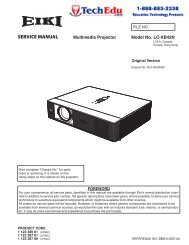
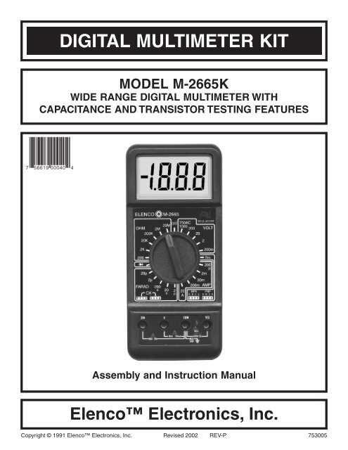
DIGITAL MULTIMETER KITMODEL M-2665KWIDE RANGE DIGITAL MULTIMETER WITHCAPACITANCE AND TRANSISTOR TESTING FEATURESAssembly and Instruction ManualElenco Electronics, Inc.Copyright © 1991 Elenco Electronics, Inc. Revised 2002 REV-P 753005
INTRODUCTIONAssembly of your M-2665 Digital Multimeter Kit willprove to be an exciting project and give muchsatisfaction and personal achievement. If you haveexperience in soldering and wiring technique, youshould have no problems. For the beginner, caremust be given to identifying the proper componentsand in good soldering habits. Above all, take yourtime and follow the easy step-by-step instructions.Remember, “An ounce of prevention is worth apound of cure”.The meter kit has been divided into a number ofsections to make the assembly easy and avoidmajor problems <strong>with</strong> the meter operation.Section A - Meter display circuit assembly.Section B - DC voltage and current circuitassembly.Section C - AC voltage and current circuitassembly.Section D - Resistance circuit assembly.Section E - Capacitance and transistor testingcircuit assembly.Section F - Final assembly.THEORY OF OPERATIONA block diagram of the M-2665K is shown in Figure 1.Operation centers around a custom LSI chip. This ICcontains a dual slope A/D converter display latchesdecoder and the display driver. A block diagram ofthe IC functions is shown in Figure 6. The inputvoltage, current or ohm signals are conditioned by thefunction and selector switches to produce and outputDC voltage between 0 and +199mV. If the inputsignal if 100VDC, it is reduced to 100mV DC byselecting a 1000:1 divider. Should the input be100VDC, then after the divider it is processed by theAC converter to produce 100mVDC. If current is to beread, it is converted to a DC voltage via internal shuntresistors. For resistance measurements, an internalvoltage source supplies the necessary 0-199mVvoltage to be fed to the IC input.V/WCOMMRangeSwitchesVWVoltageDividerOhmsConverterACConverterVWVACVAC/mA ACmAFunctionSwitchesDCAnalogDataA/DConverterandDisplayDrivermAmACurrentShuntsDecimalPointDisplayFigure 1 Simplified Block DiagramThe input of the 7106 IC is fed to an A/D (analog to<strong>digital</strong>) converter. Here the DC voltage amplitude ischanged into a <strong>digital</strong> format. The resulting signalsare processed in the decoders to light the appropriateLCD segment.Timing for the overall operation of the A/D converteris derived from an external oscillator whosefrequency is selected to be 40kHz. In the IC, this-1-frequency is divided by four before it clocks thedecade counters. It is further divided to form thethree convert-cycle phases. The final readout isclocked at about three readings per second.Digitized measurements data is presented to thedisplay as four decoded digits (seven segments) pluspolarity. Decimal point position on the display isdetermined by the selector switch setting.
A/D CONVERTERA simplified circuit diagram of the analog portion ofthe A/D converter is shown in Figure 2. Each of theswitches shown represent analog gates which areoperated by the <strong>digital</strong> section of the A/D converter.Basic timing for switch operation is keyed by anexternal oscillator. The conversion process iscontinuously repeated. A complete cycle is shownin Figure 2.Any given measurement cycle performed by the A/Dconverter can be divided into three consecutive timeperiods: autozero (AZ), integrate (INTEG) and read.Both autozero and integrate are fixed time periods.A counter determines the length of both timeperiods by providing an overflow at the end of every1,000 clock pulses. The read period is a variabletime, which is proportional to the unknown inputvoltage. The value of the voltage is determined bycounting the number of clock pulses that occurduring the read period.EXTERNALINPUTS+REF(FLYINGCAPACITOR)READBUFFERAMPCOMPARATORINTEGRATORAZAZTODIGITALCONTROLLOGICUNKNOWNINPUTVOLTAGE+INTEGINTEG.AZAZ INTEGREAD AZ+.20.15.10.050COUNTER OUTPUT0 10,000166.7mS500 1000 1500 20000Figure 2 Dual Slope A/D ConverterDuring autozero, a ground reference is applied as aninput to the A/D converter. Under ideal conditions theoutput of the comparator would also go to zero.However, input-offset-voltage errors accumulate in theamplifier loop, and appear at the comparator output asan error voltage. This error is impressed across the AZcapacitor where it is stored for the remainder of themeasurement cycle. The stored level is used to provideoffset voltage correction during the integrate and readperiods.The integrate period begins at the end of the autozeroperiod. As the period begins, the AZ switch opens andthe INTEG switch closes. This applies the unknowninput voltage to the input of the A/D converter. Thevoltage is buffered and passed on to the unknown inputvoltage to the input of the A/D converter. The voltage isbuffered and passed on to the integrator to determi<strong>net</strong>he charge rate (slope) on the INTEG capacitor. At theend of the fixed integrate period, the capacitor ischarged to a level proportional to the unknown inputvoltage. This voltage is translated to a <strong>digital</strong> indication-2-by discharging the capacitor at a fixed rate during theread period, and counting the number of clock pulsesthat occur before it returns to the original autozerolevel.As the read period begins, the INTEG switch opens andthe read switch closes. This applies a known referencevoltage to the input of the A/D converter. The polarityof this voltage is automatically selected to be oppositethat of unknown input voltage, thus causing the INTEGcapacitor to discharge as fixed rate (slope). When thecharge is equal to the initial starting point (autozerolevel), the read period is ended. Since the dischargeslope is fixed during the read period, the time requiredis proportional to the unknown input voltage.The autozero period and thus a new measurementcycle begins at the end of the read period. At the sametime, the counter is released for operation bytransferring its contents (previous measurement value)to a series of latches. This stored stat is then decodedand buffered before being used for driving the LCDdisplay.
VOLTAGE MEASUREMENTFigure 3 shows a simplified diagram of the voltagemeasurement function.The input divider resistors add up 10MW <strong>with</strong> eachstep being a division of 10. The divider outputshould be <strong>with</strong>ing –0.199 to +0.199V or the overloadindicator will function. If the AC function is selected,the divider output is AC coupled to a full waverectifier and the DC output is calibrated to equal therms level of the AC input.200mVVolts9M900k90k9k2V20V200V1kVDCACAC to DCConverterLow PassFilter100mVRef7106R1kCommonFigure 3 Simplified Voltage Measurement DiagramCURRENT MEASUREMENTFigure 4 shows a simplified diagram of the currentmeasurement positions.Internal shunt resistors convert the current tobetween –0.199 to +0.199V which is thenprocessed in the 7106 IC to light the appropriateLCD segments. If the current is AC in nature, theAC converter changes it to the equivalent DC value.200mAA200m20mA200mA20A9002mA10020mA200mA20A2mAACAC - DCConverterDCLowPassFilter100mVRef7106R9WCOM1W20AShunt.01WFigure 4 Simplified Current Measurement Diagram-3-
RESISTANCE MEASUREMENTSFigure 5 shows a simplified diagram of the resistance measurement function.100DCWLowPassFilterExternalResistor9009k90k900k9M20k2k 200200k2M20MVoltageSourceAC CAPReferenceVoltage7106RFigure 5 Simplified Resistance Measurement DiagramA simple series circuit is formed by the voltagesource, a reference resistor from the voltage divider(selected by <strong>range</strong> switches), and the externalunknown resistor. The ratio of the two resistors isequal to the ratio of their respective voltage drops.Therefore, since the value of one resistor is known,the value of the second can be determined by usingthe voltage drop across the known resistor as areference. This determination is made directly bythe A/D converter.Overall operation of the A/D converter during aresistance measurement is basically as describedearlier in this section, <strong>with</strong> one exception. Thereference voltage present during a voltagemeasurement is replaced by the voltage dropacross the reference resistor. This allows thevoltage across the unknown resistor to be readduring the read period. As before, the length of theread period is a direct indication of the value of theunknown.-4-
ASSEMBLYThe meter kit has been divided into a number ofsections to make the assembly easy and avoidmajor problems <strong>with</strong> the meter operation.OPEN ONLY THOSE COMPONENT BAGS THATARE CALLED FOR IN YOUR ASSEMBLYPROCEDURE. DO NOT OPEN ANY OTHERBAGS.Do not build more than one section of your meter ata time. Your instructor must approve the properoperation of the section you have built before youproceed to the next section. This procedure willminimize the problems you may have at thecompletion of the project.Your kit program is divided into Sections “A – F”.The small parts bags will be marked accordingly.The sections are listed below.Section A - Meter display circuit assembly.Section B - DC voltage and current circuitassembly.IMPORTANT CONSTRUCTION NOTES1. Wash your hands <strong>with</strong> soap and water before youassemble this kit. The high impedance areas onthe circuit board can be contaminated by saltand oil from your skin. If these areas becomecontaminated, your completed <strong>multimeter</strong> maynot meet the listed specifications. Handle thecircuit board only by its edges.2. Avoid any excessive accumulation of resin buildupwhenever you solder a connection.3. Take your time assembling the circuit board.Work at a slow pace. Remember that accuracyis far more important than speed.4. When you perform the steps in assembly, identifyeach respective component before you install it.Then position it over its outline on the top legendside of the PC board, unless otherwise indicated.5. Check for the proper polarity of ICs, diodes,electrolytic capacitors, battery snap and LCD.Section C - AC voltage and current circuitassembly.Section D - Resistance circuit assembly.Section E - Capacitance and transistor testingcircuit assembly.Section F - Final assembly.-6-
CONSTRUCTIONIntroductionThe most important factor in assembling your M-2665 Digital Multimeter Kit is good soldering techniques. Usingthe proper soldering iron is of prime importance. A small pencil type soldering iron of 25 - 40 watts isrecommended. The tip of the iron must be kept clean at all times and well tinned.Safety Procedures• Wear eye protection when soldering.• Locate soldering iron in an area where you do not have to go around it or reach over it.• Do not hold solder in your mouth. Solder contains lead and is a toxic substance. Wash your handsthoroughly after handling solder.• Be sure that there is adequate ventilation present.Assemble ComponentsIn all of the following assembly steps, the components must be installed on the top side of the PC board unlessotherwise indicated. The top legend shows where each component goes. The leads pass through thecorresponding holes in the board and are soldered on the foil side.Use only rosin core solder of 63/37 alloy.DO NOT USE ACID CORE SOLDER!What Good Soldering Looks LikeA good solder connection should be bright, shiny,smooth, and uniformly flowed over all surfaces.Types of Poor Soldering Connections1. Solder all components fromthe copper foil side only.Push the soldering iron tipagainst both the lead andthe circuit board foil.Soldering IronComponent LeadFoil1. Insufficient heat - thesolder will not flow onto thelead as shown.RosinCircuit BoardSoldering iron positionedincorrectly.2. Apply a small amount ofsolder to the iron tip. Thisallows the heat to leave theiron and onto the foil.Immediately apply solder tothe opposite side of theconnection, away from theiron. Allow the heatedcomponent and the circuitfoil to melt the solder.3. Allow the solder to flowaround the connection.Then, remove the solderand the iron and let theconnection cool. Thesolder should have flowedsmoothly and not lumparound the wire lead.4. Here is what a good solderconnection looks like.SolderFoilSolderFoilSoldering IronSoldering Iron2. Insufficient solder - let thesolder flow over theconnection until it iscovered. Use just enoughsolder to cover theconnection.3. Excessive solder - couldmake connections that youdid not intend to betweenadjacent foil areas orterminals.4. Solder bridges - occurwhen solder runs betweencircuit paths and creates ashort circuit. This is usuallycaused by using too muchsolder. To correct this,simply drag your solderingiron across the solderbridge as shown.SolderGapComponent LeadSolderSoldering IronFoilDrag-7-
RESISTOR READING EXERCISEBefore starting assembly of your <strong>digital</strong> <strong>multimeter</strong>project, you should be thoroughly familiar <strong>with</strong> the 5band color code system. Many of the resistorvalues will be identified by color bands and it is easyto mistake their value if you read the colors(1) yellow-black-black-black-brownincorrectly or read the value from the wrong end.Do the following exercise in resistor values. Placeyour answer in the box beneath the resistor.Answers are on the bottom of this page.(2) white-black-black-red-green(3) brown-red-violet-red-brown(4) green-black-green-brown-green(5) brown-black-black-black-brown(6) brown-green-gray-o<strong>range</strong>-brown(7) white-black-black-yellow-green(8) white-black-black-silver-green(9) brown-black-black-o<strong>range</strong>-green(10) o<strong>range</strong>-white-red-red-brown(11) gray-white-black-black-brown(12) brown-brown-black-red-brownAnswers to Resistor Reading Exercise: 1) 400W+1%; 2) 90kW+.5%; 3) 12.7kW+1%; 4) 5.05kW+.5%; 5) 100W+1%;6) 158kW+1%; 7) 9MW+.5%; 8) 9W+.5%; 9) 100kW+.5%; 10) 39.2kW+1%; 11) 890W+1%; 12) 11kW+1%;-9-
**SECTION AMeter Display CircuitPARTS LIST - SECTION AIf any parts are missing or damaged, see instructor or bookstore. DO NOT contact your place of purchase as they will notbe able to help you.Contact Elenco Electronics (address/phone/e-mail is at the back of this manual) for additional assistance, if needed.RESISTORSQty. Symbol Description Color Code Part #1 R24 56kW 5% 1/4W green-blue-o<strong>range</strong>-gold 1556001 R19 100kW 5% 1/4W brown-black-yellow-gold 1610001 R20 110kW 5% 1/4W brown-brown-yellow-gold 1611006 R16, 17, 18, 21, 22, 23 1MW 5% 1/4W brown-black-green-gold 171000Note: Resistor tolerance (last band) of 5-band resistors may be green instead of brown.CAPACITORSQty. Symbol Value Description Part #1 C2 100pF (101) Ceramic Capacitor 2210171 C3 .047mF (473) Mylar Capacitor 2447171 C4 .1mF (104) Mylar Capacitor 2510172 C5, C6 .22mF (224) Mylar Capacitor 252217SEMICONDUCTORSQty. Symbol Value Description Part #1 ZD 1N5232/1N752 Zener Diode 3152321 U2 4030/4070 Integrated Circuit 3340301 U1 7106R Integrated Circuit 337106RQty. Description Part #1 Liquid Crystal Display (LCD) 35114A1 Zebra 5000001 PC Board 516000A1 Solder Roll 5511351 Battery Snap (BAT) 5900981 Battery 5900091 LCD Window Plate 621002A1 Range Selector Knob 6220031 Bushing 624004* Parts installed on PC board already.MISCELLANEOUS**Qty. Description Part #1 LCD Stopper 6290051 LCD Housing 6290072 M2.3 x 6 Screw 6423601 M2.3 x 8 Screw 6424301 IC Socket 40-Pin 6640406 Slide Contact 6800161 Top Plate (A) 724001A2 Shims (see page 26) 780006ResistorPARTS IDENTIFICATIONIntegrated Circuit Top Plate (A) Liquid Crystal Display (LCD)DiodeCapacitorSocketBattery SnapLCD HousingLCD WindowPlateLCDLCD StopperCeramicMylarZebra-10-
ASSEMBLE THE FOLLOWING COMPONENTS TO THE PC BOARDIn all of the following steps the components must be installed on the top legend side of the PC board. Theboard is turned to solder the component leads on the selector switch side.Figure AAlign the notch on the socket (if any) <strong>with</strong> the notchmarked on the PC board. Solder the socket to the PCboard. Insert the IC into the socket <strong>with</strong> the notch asshown below. Note: If the IC is already inserted intothe socket, do not attempt to pull it out, as this willdamage the IC and socket. Instead, solder the socketto the PC board <strong>with</strong> the IC in it.Figure BLay resistor flat against thePC board.Figure CMount the diodes <strong>with</strong> theband in the correct directionas shown on the top legend.BandNotchU2 - 4030 IC or 4070No IC socket usedU1 - IC Socket 40-pinU1 - 7106R IC(see Figure A)R20 - 110kW 5% 1/4W Res.(brown-brown-yellow-gold)(see Figure B)C2 - 100pF (101) Ceramic Cap.(see Figure D)R21 - 1MW 5% 1/4W Res.R22 - 1MW 5% 1/4W Res.(brown-black-green-gold)(see Figure B)C3 - .047mF (473) Mylar Cap.(see Figure D)R23 - 1MW 5% 1/4W Res.(brown-black-green-gold)(see Figure B)C4 - .1mF (104) Mylar Cap.(may be marked 104)(see Figure D)R24 - 56kW 5% 1/4W Res.(green-blue-o<strong>range</strong>-gold)(see Figure B)NotchSolder the IC to the PC board<strong>with</strong> the notch in the directionshown on the top legend.C5 - .22mF (224) Mylar CapC6 - .22mF (224) Mylar Cap.(see Figure D)R16 - 1MW 5% 1/4W Res.R18 - 1MW 5% 1/4W Res.R17 - 1MW 5% 1/4W Res.(brown-black-green-gold)(see Figure B)R19 - 100kW 5% 1/4W Res.(brown-black-yellow-gold)(see Figure B)ZD - 1N5232 Diode(see Figure C)BAT - Battery SnapInsert both wires through thehole and mount the red wire tothe (+) hole and the black wireto the (–) hole. Solder thewires from the top legendside.Mount the capacitors <strong>with</strong> 1/4” ofspace between the body and thePC board. Bend cap over asshown.Figure D-11-
SECTION BDC Voltage & Current Circuit*PARTS LIST - SECTION BRESISTORSQty. Symbol Description Color Code Part #1 R13 1W .5% 1/2W brown-black-gold-green / OR brn-blk-blk-sil-grn 1110511 R12 9W .5% 1/4W white-black-black-silver-green 1190501 R6 100W .5% 1/4W brown-black-black-black-green 1310501 R5 900W .5% 1/4W white-black-black-black-green 1390501 R28 1.3kW 1% 1/4W brown-o<strong>range</strong>-black-brown-brown 1412301 R27 2kW 1% 1/4W red-black-black-brown-brown 1420301 R46 5.6kW 5% 1/4W green-blue-red-gold 1456001 R26 8.2kW 5% 1/4W gray-red-red-gold 1482001 R4 9kW .5% 1/4W white-black-black-brown-green 1490501 R25 39.2kW 1% 1/4W o<strong>range</strong>-white-red-red-brown 1539301 R3 90kW .5% 1/4W white-black-black-red-green 1590501 R2 900kW .5% 1/4W white-black-black-o<strong>range</strong>-green 1690501 R1 9MW .5% 1/2W white-black-black-yellow-green 1790511 VR1 200W / 220W Potentiometer 191320Note: Some resistors may not have a color coding, but they will have the value imprinted on them.Note: Resistor tolerance (last band) of 5-band resistors may be green instead of brown.CAPACITORSQty. Symbol Value Description Part #1 C1 22mF Electrolytic (Lytic) 272244SEMICONDUCTORSQty. Symbol Value Description Part #2 D1, D2 1N4001 or 1N4007 Diode 314001MISCELLANEOUSQty. Symbol Description Part #1 Shunt Wire M1.6 x 60 1000691 Fuse 2A 5330201 SW1 Slide Switch 5411041 Slide Switch Knob 6220042 Fuse Holder Clips 6630034 Input Socket 6640001 Test Lead Set RWTL14* Part installed on PC board already-13-
ASSEMBLE THE FOLLOWING COMPONENTS TO THE PC BOARDIn all of the following steps the components must be installed on the top legend side of the PC board. Theboard is turned to solder the component leads on the selector switch side.Figure EStand resistor on end asshown <strong>with</strong> the bodyinside the white circle.WhiteCircleFigure FLytics have a polarity marking onthem indicating the negative lead, theopposite lead is positive. The PCboard is marked to show the positive(+) lead position. Mount the capacitor<strong>with</strong> the positive (+) lead in the holemarked on the PC board. Bend thecapacitor over.+C1+R6 - 100W .5% 1/4W Res.(brown-blk-blk-blk-green)(see Figure E)R26 - 8.2kW 5% 1/4W Res.(gray-red-red-gold)(see Figure E)R5 - 900W .5% 1/4W Res.(white-blk-blk-blk-green)(see Figure E)R25 - 39.2kW 1% 1/4W Res.(o<strong>range</strong>-white-red-red-brown)(see Figure E)R4 - 9kW .5% 1/4W Res.(white-blk-blk-brown-green)(see Figure E)R3 - 90kW 1/4W .5% Res.(white-blk-blk-red-green)(see Figure E)R2 - 900kW .5% 1/4W Res.(white-blk-blk-o<strong>range</strong>-green)(see Figure E)R1 - 9MW .5% 1/2W Res.(white-blk-blk-yellow-green)(see Figure B)D1 - 1N4001 DiodeD2 - 1N4001 Diode(see Figure C)C1 - 22mF Lytic Capacitor(see Figure F)R27 - 2kW 1% 1/4W Res.(red-blk-blk-brown-brown)(see Figure E)R28 - 1.3kW 1% 1/4W Res.(brn-o<strong>range</strong>-blk-brn-brn)(see Figure E)R46 - 5.6kW 5% 1/4W Res.(green-blue-red-gold)(see Figure E)VR1 - 200WPotentiometerR12 - 9W 1/4W .5% Res.(white-blk-blk-silver-green)(see Figure B)R13 - 1W .5% 1/2W Res.(brown-black-gold-green)(see Figure B)Fuse Holder ClipsFuse 2AMount holders <strong>with</strong> the tabside as shown on the toplegend then insert fuse.ShuntPush into boardup to stopsTab-14-
PARTS LIST - SECTION ESECTION ECapacitance and Transistor Testing CircuitRESISTORSQty. Symbol Description Color Code Part #1 R7 98.8W 1% 1/4W white-gray-gray-gold-brown 1298301 R37 150W 5% 1/4W brown-green-brown-gold 1315001 R8 900W 1% 1/4W white-black-black-black-brown 1390301 R41 1.91kW 1% 1/4W brown-white-brown-brown-brown 1419301 R40 4.12kW 1% 1/4W yellow-brown-red-brown-brown 1441301 R9 9kW 1% 1/4W white-black-black-brown-brown 1490301 R38 10kW 1% 1/4W brown-black-black-red-brown 1510301 R43 11kW 1% 1/4W brown-brown-black-red-brown 1511302 R39, R42 39.2kW 1% 1/4W o<strong>range</strong>-white-red-red-brown 1539301 R44 76.8kW 1% 1/4W violet-blue-gray-red-brown 1576301 R10 90kW 1% 1/4W white-black-black-red-brown 1590301 R45 158kW 1% 1/4W brown-green-gray-o<strong>range</strong>-brown 1615302 R14, R15 240kW 5% 1/4W red-yellow-yellow-gold 162400OR red-yellow-black-o<strong>range</strong>-green1 R11 909kW 1% 1/4W white-black-white-o<strong>range</strong>-brown 1690601 VR2 200W / 220W Potentiometer 191320Note: Resistor tolerance (last band) of 5-band resistors may be green instead of brown.CAPACITORSQty. Symbol Value Description Part #4 C10 - C13 .01mF (103) Mylar 241017SEMICONDUCTORSQty. Symbol Value Description Part #1 U4 324 / 17324 Integrated Circuit 3303244 D3 - D6 1N4001 or 1N4007 Diode 3140011 D11 1N4148 Diode 314148MISCELLANEOUSQty. Symbol Description Part #2 hFE, CX 9-pin Socket 6640091 U4 IC Socket 14-pin 664014-18-
ASSEMBLE THE FOLLOWING COMPONENTS TO THE PC BOARDIn all of the following steps the components must be installed on the top legend side of the PC board. Theboard is turned to solder the component leads on the selector switch side.R44 - 76.8kW 1% 1/4W Res.(violet-blue-gray-red-brown)(see Figure E)R43 - 11kW 1% 1/4W Res.(brown-brown-blk-red-brn)(see Figure E)R42 - 39.2kW 1% 1/4W Res.(o<strong>range</strong>-white-red-red-brn)(see Figure E)R14 - 240kW 5% 1/4W Res.R15 - 240kW 5% 1/4W Res.(red-yellow-yellow-gold)(see Figure B)C12 - .01mF (103) Mylar Cap.C13 - .01mF (103) Mylar Cap.D3 - 1N4001 DiodeD4 - 1N4001 Diode(see Figure H)R45 - 158kW 1% 1/4W Res.(brown-grn-gray-o<strong>range</strong>-brn)(see Figure E)U4 - IC Socket 14-pinU4 - 324 Integrated CircuitAlign the notch on the socket (ifany) <strong>with</strong> the notch marked onthe PC board. Solder the socketto the PC board. Insert the ICinto the socket <strong>with</strong> the notch asshown below.NotchD11 - 1N4148 Diode(see Figure C)R7 - 98.8W 1% 1/4W Res.(wht-gray-gray-gold-brn)(see Figure E)R8 - 900W 1% 1/4W Res.(wht-blk-blk-blk-brn)(see Figure E)R9 - 9kW 1% 1/4W Res.(wht-blk-blk-brn-brn)(see Figure E)R10 - 90kW 1% 1/4W Res.(wht-blk-blk-red-brn)(see Figure E)R11 - 909kW 1% 1/4W Res.(wht-blk-wht-org-brn)(see Figure E)VR2 - 200WPotentiometerD5 - 1N4001 DiodeD6 - 1N4001 Diode(see Figure H)R39 - 39.2kW 1% 1/4W Res.(org-wht-red-red-brn)(see Figure E)R37 - 150W 5% 1/4W Res.(brn-grn-brn-gold)(see Figure E)C11 - .01mF (103) Mylar Cap.C10 - .01mF (103) Mylar Cap.R41 - 1.91kW 1% 1/4W Res.(brn-wht-brn-brn-brn)(see Figure E)R38 - 10kW 1% 1/4W Res.(brn-blk-blk-red-brn)(see Figure E)R40 - 4.12kW 1% 1/4W Res.(yel-brn-red-brn-brn)(see Figure E)-19-
Mount the two 9-pin component sockets to the PC board <strong>with</strong> the notch at the base of the socket in thedirection shown in Figure I. Solder the sockets in place from the top legend side.Component SocketNotchComponent SocketNotchTesting ProcedureConnect the 9V battery and test leads to the meter(red to VW and black to COM). Set the <strong>range</strong>selector knob to the diode scale and set SW1 in theDC Ohm position. Connect a diode to the test leads<strong>with</strong> the correct polarity (see figure below). TheFigure Imeter will <strong>range</strong> for 100 - 950. If the tests are notworking, check for cold solder joints and part values.Turn the meter off and remove the battery and testleads.COMVWDO NOT PROCEED TO SECTION E WITHOUT INSTRUCTOR’S APPROVAL.PARTS LIST - SECTION FSECTION FFinal AssemblyQty. Description Part # Qty. Description Part #1 Battery Cushion 620001 1 Shield Spring 6800081 Top Case 623101A 2 Knob Spring 6800091 Bottom Case w/Stand 623200A 1 Top Plate (B) 724000A3 Screw M2.3 x 6 642360 1 Shield 7800082 Screw M3 x 12 642367 1 Grease 7900042 Bearing 666001Note: The shield and battery cushion may be installed already.-20-
Top Plates(A)(B)Top CaseSpringsBearingsBallBearingSpringGreaseSelectorKnobSpringRange Selector KnobBatteryShield PlateBottom CaseFigure KBatteryCushionM3 x 12 ScrewsStand-22-
Testing Procedure SECTION C - AC voltageand current circuitMeasure an AC voltage <strong>with</strong> a known accuratemeter. Now measure the voltage <strong>with</strong> the kit meter.The meters should be the same voltage.Connect the kit meter and another meter of knownaccuracy in series. Set the meters in the 200mAposition. Construct a circuit for an AC current andmeasure the circuit current. Both meters shouldhave close to the same readings. If the meters donot agree, check the parts just added. Do not readjustVR1 this will change the voltage reading setin step 1. Check the 200m - 200mA scales. The 20Ascale requires, a circuit of 1 - 10 amps. If the testsare not working, check for cold solder joints and partvalues. DO NOT PROCEED TO SECTION FWITHOUT INSTRUCTORS APPROVAL.Testing Procedure SECTION FSet the meter in one of the farad scales. Make surethat SW1 is in the AC/Cap position. Measure a cap<strong>with</strong> another meter and then insert the same capinto the kit meters CX connectors. Adjust VR2 sothat the meter reads the same as the accurate one.This calibrates capacitance circuit of meter. Usingtwo or three different value capacitors, check eachscale. Compare the kit meter readings <strong>with</strong> anothermeter. Turn the meter off and remove the battery.Set the meter in the hFE scales. Place an NPNtransistor into the socket. Make sure that thetransistor is in correctly. Depending on the type oftransistor, the meter will <strong>range</strong> from 20 to 550.Place a PNP transistor into the PNP socket, the<strong>range</strong> will also be 20 to 550. If the tests are notworking, check for cold solder joints and part values.-23-
Amps Section1. 200mA scale not working:A. Check fuse.B. Measure across (A) terminal and (COM)terminal for 1W (set meter in 200mA).1. Lower or higher than 1W, Check R13.2. 20mA scale not working:A. Check fuse.B. Measure between (A) terminal and(COM) for 10W (set meter in 20mA).1. Lower or higher than 10W, check R12and R13.Capacitance Section1. Place .001mF cap in the socket and check pin 7and pin 8 of U4 <strong>with</strong> a scope (meter set to 2N).Pin 7 370Hz - 400Hz .12Vpp.hFE Section1. Check for shorts on socket pins.2. Measure across B terminal to COM terminal for251kW.A. Lower or higher than 251kW; Check R14and R15.Decimal Point Section1. Displays two decimal points.A. Shorted output on U2.2. No decimal points displayed.DiodeA. Check U2 325.1. Measure voltage across V OHM and COMterminal (set in diode mode) = 1.3V.A. Low voltage, check R26.Battery Low Indicator1. Not working.Pin 14 370Hz - 400Hz .3Vpp.A. Check ZD1, R19 and U2.A. No signal at pin 14.1. Check D3, D4 and shorts.B. No signal at pin 7 but present at pin 1.1. Check D5 and D6.-25-
REINSTALLATION OF THE RANGE SELECTOR KNOBIf you removed the <strong>range</strong> selector knob for troubleshooting,then follow the instructions below to reinstall it.Place the PC board over the <strong>range</strong> selector knob andfasten the knob to the PC board <strong>with</strong> a M2.3 x 8 screw.CAUTION: Do not overtighten the screw. The knobshould be snug, but not loose. Turn back the M2.3 x 8screw 1/2 turn. Slip the two shims under the knob (seeFigure L). If they do not slip in, turn back the screwanother 1/4 turn. Tighten the screw just enough so thatthe shims can be pulled out. You should now have theproper tension to hold the knob and contacts in place androtate the knob to the desired positions.Bottom View of Selector Knob& Slide ContactsSlide ContactShimFigure LShimUSING THE DIGITAL MULTIMETERFamiliarize yourself <strong>with</strong> your new <strong>digital</strong> meter bytaking readings of known resistances and voltages.You will find that the readings will not be as accurateon certain <strong>range</strong>s for a given measurement. Forexample, when measuring a low resistance on ahigh <strong>range</strong>, the reading will show a short 0.00.When measuring a high resistance on a low <strong>range</strong>,the reading will show infinity 1. Likewise, it isimportant to use the correct <strong>range</strong> when measuringvoltages.MEASUREDRANGE SETTINGRESISTANCE 200W 2kW 20kW 200kW 2MW 20MW* 00.1 .000 0.00 00.0 .000 0.00SHORT(LEADS TOUCHING)Table 1 shows an example of the readouts fordifferent values of resistance. Table 2 shows anexample of the readouts for 117VAC and 100VDC.The shaded area indicates the most accurate <strong>range</strong>.It must be remembered that the readings will shiftslightly when switching to a different <strong>range</strong>.INFINITY 1 . 1. 1 . 1 . 1. 1 .47W 52.1 .052 0.05 00.0 .000 0.00270W 1 . .267 0.26 00.2 .000 0.0010kW 1 . 1. 10.18 10.2 .010 0.0147kW 1 . 1. 1 . 52.7 .052 0.05470kW 1 . 1. 1 . 1 . .472 0.472.2MW 1 . 1. 1 . 1 . 1. 2.12* RESISTANCE OF TEST LEADSTable 1Table 2MEASUREDVOLTAGE 200mV 2V 20V 200V 1000V117VAC 1 . 1. 1 . 117.0 117100VDC 1 . 1. 1 . 100.0 100-26-
1. FEATURES• <strong>Wide</strong> measuring <strong>range</strong>s:34 <strong>range</strong>s for AC/DC Voltage and Current, Resistance, Capacitance, TR hFE,Diode Test.• 10MW Input Impedance• Big LCD for easy reading• Tilt Stand2. SPECIFICATIONS2-1 General SpecificationsDisplay 3 1/2 LCD 0.95” height, maximum reading of 1999.PolarityOver<strong>range</strong> IndicationLow Battery IndicationAutomatic “–” sign for negative polarity.Highest digit of “1” or “–1” is displayed.“BAT” lettering on the LCD readout.Operating Temperature 0 O C to 50 O C.less than 80% relative humidity up to 35 O C.less than 70% relative humidity from 35 O C to 50 O C.Storage Temperature–15 O C to 50 O CTemperature Coefficient 0 O C to 18 O C and 28 O C to 50 O C.less than 0.1 x applicable accuracy specification per degree C.Power 9V alkaline or carbon zinc battery (NEDA 1604).Battery Life (typical)DimensionsWeightAccessories100 hours <strong>with</strong> carbon zinc cells.200 hours <strong>with</strong> alkaline cells.3.47” (88mm) (W) x 7.52” (191mm) (L) x 1.42” (36mm) (H).Approximately 10.4oz. (300g.)Safety Test Lead 1 pair2-2 Measurement Ranges (Accuracy: 1 year 18 O C to 28 O C)DC VoltageRange Resolution Accuracy Maximum Input200mV 100mV +0.5% of rdg + 2dgt2V 1mV +0.5% of rdg + 2dgt20V 10mV +0.5% of rdg + 2dgt DC 1000V or peak AC200V 100mV +0.5% of rdg + 2dgt1000V 1V +0.5% of rdg + 2dgtNormal Mode Rejection Ratio: Greater than 46dB at 50Hz 60Hz (1k unbalance)-27-
AC VoltageRange Resolution Accuracy Maximum Input200mV 100mV +1.2% of rdg + 2dgt2V 1mV +1.2% of rdg + 2dgt20V 10mV +1.2% of rdg + 2dgt AC 750V maximum 50Hz - 400Hz200V 100mV +1.2% of rdg + 2dgt750V 1V +1.2% of rdg + 2dgtResistanceRange Resolution Accuracy Test Current Input Protection200W 0.1W +0.8% of rdg + 2dgt2kW 1W +0.8% of rdg + 2dgt20kW 10W +0.8% of rdg + 2dgt Approximately Protected By200kW 100W +0.8% of rdg + 2dgt 1.2mA PTC2MW 1kW +1.0% of rdg + 3dgt20MW 10kW +3.0% of rdg + 4dgtMaximum open circuit voltage: 2.8VDC CurrentRange Resolution Accuracy Protection200mA 100nA +0.5% of rdg + 2dgt2mA 1mA +0.5% of rdg + 2dgt Protected by20mA 10mA +0.5% of rdg + 2dgt 250V/2A Fuse200mA 100mA +0.5% of rdg + 2dgt20A 10mA +1.0% of rdg + 3dgtAC CurrentRange Resolution Accuracy Protection200mA 100nA +1.2% of rdg + 3dgt2mA 1mA +1.2% of rdg + 3dgt Protected by20mA 10mA +1.2% of rdg + 3dgt 250V/2A Fuse200mA 100mA +1.2% of rdg + 3dgt20A 10mA +3.0% of rdg + 3dgtCapacitanceRange Resolution Accuracy Protection2nF 1pF +3.0% of rdg + 3dgt2nF 10pF +3.0% of rdg + 3dgt200nF 100pF +3.0% of rdg + 3dgt Test frequency 400Hz+3.0% Test Voltage 120mV2mF 1nF +3.0% of rdg + 3dgt20mF 10nF +3.0% of rdg + 3dgt-28-
Transistor hFERange Test ConditionNPN 10mA 2.8VPNP 10mA 2.8VDiode TestMeasures forward resistance of a semiconductor junction in k Ohm at max. test current of 1.5mA.3. OPERATION3-1 Preparation and caution before measurement1. If the function must be switched during ameasurement, always remove the test leadsfrom the circuit being measured.2. If the unit is used near noise generatingequipment, be aware that the display maybecome unstable or indicate large errors.4. In order to prevent damage or injury to the unit,never fail to keep the maximum tolerable voltageand current, especially for the 20A current <strong>range</strong>.5. Carefully inspect the test lead. If damaged,discard and replace.3. Avoid using the unit in places <strong>with</strong> rapidtemperature variations.3-2 Panel DescriptionLCD DisplaySelector SwitchRange Selector KnobCapacitor Input SockethFE Input Socket20A Input Jack(200mA Max) A input JackVolt Ohm Input JackCommon Input Jack-29-
3-3 Method of Measurement(A) DC/AC Voltage Measurement1. Set the selector switch to “DC” or “AC”.2. Connect the red test lead to “V/W” input jack andthe black one to the “COM” jack.3. Set the <strong>range</strong> selector knob to the desired voltposition. If the magnitude of the voltage is notknown, set the <strong>range</strong> selector knob to thehighest <strong>range</strong> and reduce until a satisfactoryreading is obtained.4. Connect the test leads to the device or circuitbeing measured.5. Turn on the power to the device or circuit beingmeasured. The voltage value will appear on the<strong>digital</strong> display along <strong>with</strong> the voltage polarity.6. Turn off the power to the device or circuit beingtested and discharge all of the capacitors prior todisconnecting the test leads.(C) Resistance Measurement1. Set the selector switch to the “Ohm” position.2. Connect red test lead to the “V/W” input jack andthe black one to “COM”.3. Set the <strong>range</strong> selector knob to desired “Ohm”position.4. If the resistance being measured is connected toa circuit, turn off the power to the circuit beingtested and discharge all capacitors.5. Connect the test leads to the circuit beingmeasured. When measuring high resistance, besure not to contact adjacent point even ifinsulated, because some insulators have arelatively low insulation resistance, causing themeasured resistance to be lower than the actualresistance.6. Read resistance value on <strong>digital</strong> display.(B) DC/AC Current Measurement1. Set the selector switch to “DC” or “AC”.2. Connect the red test lead to the “A” input jack forcurrent measurement up to 200mA, and theblack one to “COM”.3. Set the <strong>range</strong> selector knob to the desired “Amp”current position.If the magnitude of current is not known, set therotary/function switch to the highest <strong>range</strong> andreduce until a satisfactory reading is obtained.4. Open the circuit to be measured, and connectthe test leads in series <strong>with</strong> the load in whichcurrent is to be measured.5. Read the current value on the <strong>digital</strong> display.6. Turn off all power to the circuit being tested anddischarge all of the capacitor prior todisconnecting the test lead.7. To measure in the 20A <strong>range</strong>, use the “20A” jackas the input jack. Be sure to measure <strong>with</strong>in 10seconds to avoid high-current hazard.-30-
(D) Diode Test1. Set the selector switch to the “Ohm” position.2. Connect the red test lead to “V/W” input jack andthe black one to the “COM” jack.3. Set the <strong>range</strong> selector knob to the “ ”position.4. If the semiconductor junction being measured isconnected to the circuit, turn off the power to thecircuit being tested and discharge all of thecapacitors.5. Connect the test leads to the device and readforward value on the <strong>digital</strong> display.6. If the <strong>digital</strong> reads over<strong>range</strong> (1), reverse thelead connections.The placement of the test leads when theforward reading is displayed indicates theorientation of the diode.The red lead is positive and the black lead isnegative.If over<strong>range</strong> (1) is displayed <strong>with</strong> both leadconnections, the junction is open.(F) Capacitance Measurement1. Set the <strong>range</strong> selector knob to the “FARAD”position.2. Set the <strong>range</strong> selector knob to the desiredcapacitance position.3. Short the leads of the capacitor to be testedtogether to insure that there is no charge on thecapacitor.4. Insert the capacitor leads into the capacitor testsocket. Note that there are two groups of holes.One lead must be inserted into one of group one,and the other lead must be inserted into one ofthe holes of group two.5. Read the capacitance value on the <strong>digital</strong>display.(E) Transistor hFE Measurement1. Set the selector switch to “DC”.2. The transistor must be out of circuit. Set therotary/function switch to the hFE position.3. Plug the emitter, base and collector leads of thetransistor into the correct holes in either the NPNof the PNP transistor test socket, whichever isappropriate for the transistor you are checking.4. Read the hFE (beta or DC current gain) on thedisplay.-31-
4. OPERATION MAINTENANCE4-1 Battery and Fuse ReplacementCAUTIONBEFORE ATTEMPTING BATTERY REMOVAL ORREPLACEMENT, DISCONNECT THE TESTLEADS FROM ANY ENERGIZED CIRCUITS TOAVOID SHOCK HAZARD.The fuse rarely needs replacement and blow almostalways as a result of operator error. To replace thebattery and fuse (2A/250V), remove the two screwsin the bottom of the case. Simply remove the oldbattery or fuse and replace <strong>with</strong> a new one.Remove the two phillips head screws. Carefullyremove the plastic back cover. With the instrumentoperating and set to the 200mV DC <strong>range</strong> (20mFcapacitance <strong>range</strong>), apply 190mV DC (10mF) froman accurate source. With a small screwdriverinserted into the semi-fixed resistor VR1 (VR2:Capacitance), carefully turn the variable resistoruntil the reading reads 190mV (10mF).NOTE: Be sure to proceed basic calibration by DC<strong>range</strong> first prior to capacitance.Be sure to observe the polarity when replacing thebattery.4-2 Calibration ProcedureIt is normally not necessary to recalibrate for longintervals. If needed, adjustment should be done<strong>with</strong> highly accurate standards (setter than 0.1%accuracy).5. SAFETY SYMBOLS!This marking adjacent to another marking or aterminal operating device indicates that theoperator must refer to an explanation in theoperating instructions to avoid damage to theequipment and/or to avoid personal injury.WARNINGCAUTION500V max.This WARNING sign denotes a hazard. It callsattention to a procedure, practice or the like, whichif not correctly performed or adhered to, could resultin personal injury.This CAUTION sign denotes a hazard. It callsattention to a procedure, practice or the like, whichif not correctly adhered to, could result in damage toor destruction of part or all of the instrument.This marking advises the user that the terminal(s)so marked must not be connected to a circuit pointat which the voltage, <strong>with</strong> respect to earth ground,exceeds (in this case) 500 volts.This symbol adjacent to one or more terminalsidentifies them as being associated <strong>with</strong> <strong>range</strong>s thatmay in normal use be subjected to particularlyhazardous voltages. For maximum safety, theinstrument and its test leads should not be handledwhen these terminals are energized.-32-
SCHEMATIC DIAGRAM-33-
QUIZ1. The function of the A/D converter is to . . .A. convert <strong>digital</strong> to analog.B. divide analog signal by 2.C. convert analog to <strong>digital</strong>.D. convert AC to DC.2. What type of divider <strong>net</strong>work is used for voltagemeasurements?A. Divide by 20.B. Capacitance.C. Divide by 5.D. Resistor.3. When the AC voltage is measured, it is first . . .A. divided down by 2.B. converted to DC.C. coupled to a halfwave rectifier.D. low voltage.4. When measuring current, the shunt resistorsconvert the current to . . .A. +0.190 to –0.190.B. –1.199 to +1.199.C. –0.099 to +0.099.D. –199 to +0.199.5. Which IC drives the LCD?A. 358.B. LM324.C. 7106R.D. 1N5232.6. Resistance measurements are made by . . .A. comparing voltage drops in the unknownresistor and a reference resistor.B. measuring the current in the unknownresistor.C. measuring the current in the referenceresistor.D. equalizing the voltage drop in the unknownand reference resistor.7. Measurement cycles performed by the A/Dconverter can be divided into what types of timeperiods?A. Long, short.B. Auto zero, integrate, read.C. Zero, read, interphase.D. Autozero, read, cycle phase.8. A resistor <strong>with</strong> band colors green-black-greenbrown-greenis what value?A. 50.5kW + 5%.B. 5.15kW + 10%.C. 5.05kW + .5%.D. 5.05kW + 1%.9. When checking a transistor, the selector knobshould be in the . . .A. farad position.B. ohm position.C. diode position.D. hFE position.10. Where do the leads need to be on the meterwhen measuring 450mA?A. A20, COM.B. V, COM.C. A, A20.D. A, COM.Answers: 1. C, 2. D, 3. B, 4. B, 5. C, 6. A, 7. B, 8. C, 9. D, 10. A-34-
Elenco Electronics, Inc.150 W. Carpenter AvenueWheeling, IL 60090(847) 541-3800http://www.elenco.come-mail: elenco@elenco.com