Downloads - Riello Burners
Downloads - Riello Burners Downloads - Riello Burners
- Page 3: TECHNICAL FEATURESTYPE - Boiler Mod
- Page 6: OIL LINESD5307min. 0.1 mHmax. 4 mH
- Page 9 and 10: THE BURNERS LEAVE THE FACTORY SET A
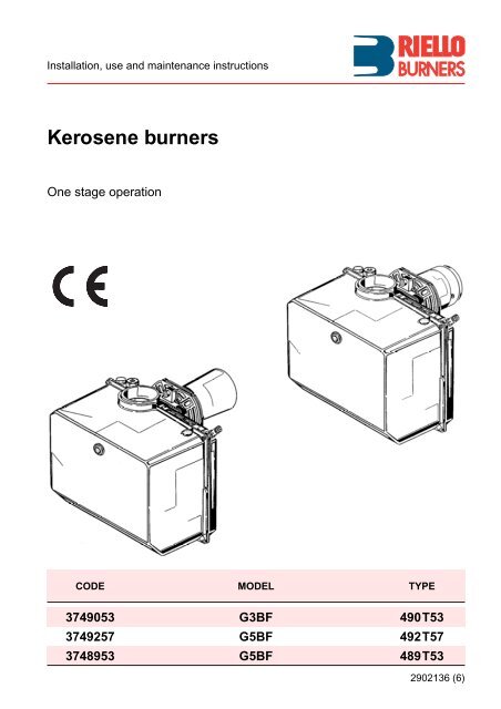
TECHNICAL FEATURESTYPE - Boiler Model 490 T53 – 50 / 70 492T57 – 70 / 90 489 T53 – 90 / 120Thermal power – output 19 – 35 kW 17 – 42 kW 28 – 60 kW(with air at 20°C)1.6 – 3 kg/h 1.5 – 3.5 kg/h 2.3 – 5 kg/hFuelkerosene, 28 sec.Electrical supply single phase, 230V ± 10% ~ 50HzMotorrun current 0.85A – 2850 rpm – 298 rad/sCapacitor4 mFIgnition transformer secondary, 8 kV – 16 mAPumpmaximum pressure 14 bar (203 psi)Absorbed electrical power 0.15 kW 0.16 kW 0.16 kW◆ Burner with CE marking in conformity with EEC directives: EMC89/336/EEC, Low Voltage 73/23/EEC,Machines 89/392/EEC and Efficiency 92/42/EEC.◆ The intake air temperature must not be over 70°C.◆ The burner meets protection level of IP 54, EN 60529.◆ Kit for two pipes system code 3000970490 T53 - 492T5711179Fig. 163582489 T5310124D54221 – Suction line2 – Gauge connection3 – Pump pressure regulator4 – Vacuum gauge connection5 – Air-damper6 – Regulating air-damper rod7 – Lock-out lamp and reset button8 – Flange with insulating gasket9 – Wiring loom fitting10 – Relief valve11 – Air socket from the outside12 – Combustion head adjustment screwD542321361
WORKING RANGE (as EN 267)Pressure in the combustionchamber – mbarD54250.80.60.40.2490 T5301.5 2 2.5 3 Fuel output - kg/h20 25 30 35 Thermal power - kWPressure in the combustionchamber – mbarD54260.80.60.40.20492 T571.5 2 2.5 3 3.5 Fuel output - kg/h20 25 30 35 40 Thermal power - kWPressure in the combustionchamber – mbar0.80.60.40.20489 T532 2.3 3 4 5 Fuel output - kg/hD5226 25 30 35 40 45 50 55 60 Thermal power - kW21363
OIL LINESD5307min. 0.1 mHmax. 4 mH = Difference of level.L = Max. length of the suction line.I.D.= Internal diameter of the oil pipes.Hmeters0.511.52L metersI. D.8 mm10204060I.D.10 mm204080100PRIMING THE PUMPLoosen the plug of the vacuum gauge (4, fig. 1, page 1)and wait until the fuel flows out.HD5308max. 4 mHmeters00.511.5233.5L metersI. D.8 mm353025201586I.D.10 mm10010010090703020AD5199HWARNINGThe pump is supplied for use with a one pipe system.For use on a two pipes system, it is necessary to screw theBY-PASS SCREW (A) supplied with kit code 3000970.The pump vacuum should not exceed a maximum of 0.4 bar (30 cm Hg). Beyond this limit gas is releasedfrom the oil. Oil lines must be completely airtight. The return line should terminate in the oil tankat the same level as the suction line; in this case a non-return valve is not required.Should however the return line arrives over the fuel level, the non-return valve is indispensable.This solution however is less safe than previous one, due to the possibility of leakage of the valve.PRIMING THE PUMP:Start the burner and wait for the priming. Should lock-out occur prior to the arrival of the fuel, await atleast 20 seconds before repeating the operation.WARNING: Before starting the burner make sure that the return pipe-line is not clogged: anyobstruction would cause the pump seals to break.WARNING■ Check periodically the flexible pipes conditions.Using kerosene, they have to be replaced at least every 2 years.■ A metal bowl filter with replaceable micronic filter must be fitted in the oil supply pipe.21364
COMBUSTION ADJUSTMENTIn conformity with Efficiency Directive 92/42/EEC the application of the burner on the boiler, adjustmentand testing must be carried out observing the instruction manual of the boiler, including verification of theCO and CO 2 concentration in the flue gases, their temperatures and the average temperature of the waterin the boiler.To suit the required appliance output, fit the nozzle then adjust the pump pressure, (the setting of the combustionhead for type 489 T53) and the air damper opening in accordance with the following schedule.TYPENozzle Pump pressure Burner Comb. head Air damperoutput adjustment adjustment1 2 3 4GPH Angle bar kg/h ± 4% Set-point Set-point490 T53492 T57489 T530.50 60° 8 1.5 2.50.60 60° 8 1.7 3.00.65 60° 8 1.9 3.30.75 60° 8 2.2 3.90.85 60° 8 2.5 4.21.00 60° 8 2.9 6.01.00 60° 9 3.0 8.0For 1.00 GPH nozzles it is advisable to use , if possible, full cones.0.50 60° 8 1.5 2.20.60 60° 8 1.7 2.40.65 60° 8 1.9 2.60.75 60° 8 2.2 3.00.85 60° 8 2.5 3.21.00 60° 8 2.9 3.91.10 60° 8 3.4 5.2For 1.00 - 1.10 GPH nozzles it is advisable to use , if possible, full cones.0.75 60° 8 2.2 0 2.80.85 60° 8 2.5 0.5 3.01.00 60° 8 2.9 1.5 3.21.10 60° 8 3.2 2.0 3.51.25 60° 8 3.7 3.0 4.01.35 60° 8 4.0 4.0 4.21.50 60° 8 4.4 5.0 4.91.50 60° 10 5.0 6.0 6.5The settings indicated in the schedule refer to the burner with its metal cover fitted and the combustionchamber with “zero” depression. These regulations are purely indicative. Each installation however,has its own unpredictable working conditions: actual nozzle output; positive or negative pressure inthe combustion-chamber, the need of excess air, etc. All these conditions may require a different airdampersetting.12NOZZLES RECOMMENDED: Monarch type R - NS ; Delavan type W - A - E - BSteinen type Q - H ; Danfoss type B - H - SAngle: 60° - in most cases.80° - in case of flame detachment, during ignitions at low temperatures.PRESSURE:8 bar : the pump leaves the factory set at this value.10 bar : maximum pressure for kerosene.21366
THE BURNERS LEAVE THE FACTORY SET AT THESE VALUESTYPENozzlePumpPressureComb. headadjustmentAir damperadjustmentbar Set-point Set-point490 T53 Danfoss 0.60 GPH - 80° H 8 – 3.8492 T57 Danfoss 0.75 GPH - 80° H 8 – 4.0489 T53 Danfoss 1.00 GPH - 80° H 8 2.5 3.93COMBUSTION HEAD SETTING (Only type 489 T53)This is done when fitting the nozzle, with the blast tube removed.It depends on the output of the burner and is carried out by rotating the regulating rod, till the terminalplane of the blast tube is level with the set-point, as indicated in the schedule.In the sketch below, the combustion head is set for an output of 1.25 GPH at 8 bar.The shutter is level with set-point 3, as required by the schedule at page 6.Terminal plane of the blast tube2 31265 3 1Regulating rodD5232Blast tubeShutterD5233Combustion head settings indicated in the schedule are valid for most cases.The setting of the fan output according to the installation should normally be done only through the airdamper. Should one subsequently want to retouch also the setting of the combustion head, with theburner running, operate on the rod (1) with a 6 mm spanner (2) as follows:TURN TO THE RIGHT : (sign +)In order to increase the volume of air entering the combustion chamber and thus diminishing its pressure.There is a reduction of CO 2 and the adhesion of the flame to the air diffuser disc improves. (Settingadvisable for ignitions at low temperatures).TURN TO THE LEFT : (sign –)In order to reduce the volume of air entering the combustion chamber and thus increasing its pressure.The CO 2 improves and the adhesion of the flame to the diffuser tends to reduce. (This setting is notadvisable for ignitions at low temperatures).In any case do not bring the combustion head setting more than one point away from that indicated inthe schedule. One set-point corresponds to 3 turns of the rod; a hole (3) at its end facilitates countingthe number of turns.21367
3AIR DAMPER ADJUSTMENTThe air-output setting can be carried out acting with the rod(2) on the screw (1) that makes the air-damper (3) turn.Further retouchs can be carried out without removing thecover but unscrewing the plug (A) as shown in the figure onthe below.21Turn to the right (sign +) to increase theair quantity in the combustion chamber,turn to the left (sign –) to decrease it.3D5141S7021ELECTRODE SETTINGAttention:Before assembling or removing thenozzle, loosen the screw (A) andmove the electrodes ahead.4 ± 0.3 mmWARNINGMEASURESMUST BE RESPECTEDD5230A2 – 2.5 mmBURNER START-UP CYCLEThermostatMotorIgnition transformerValveFlameLock-out lampNormal~ 12sLock-out, due to light-failure~ 12s ~ 5sD522921368


