Invacare ® Storm ³ Invacare ® Storm ³ Euro Invacare ® Storm ³ ...
Invacare ® Storm ³ Invacare ® Storm ³ Euro Invacare ® Storm ³ ...
Invacare ® Storm ³ Invacare ® Storm ³ Euro Invacare ® Storm ³ ...

Create successful ePaper yourself
Turn your PDF publications into a flip-book with our unique Google optimized e-Paper software.
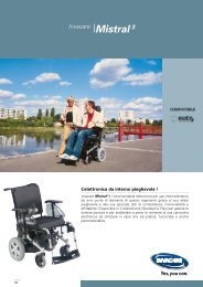
<strong>Invacare</strong> ® <strong>Storm</strong> ³<strong>Invacare</strong> ® <strong>Storm</strong> ³ <strong>Euro</strong><strong>Invacare</strong> ® <strong>Storm</strong> ³ VerticSERVICE INSTRUCTIONSEdition: 18.04.12
SERVICE MANUAL <strong>Invacare</strong> ® - STORM 3These instructions contain information about:Testing workRepair InstructionsThis manual is part of the instructions for use.Service addresses<strong>Invacare</strong> Austria GmbHHerzog Odilostrasse 101A-5310 MondseeAustria: +43 6232 5 53 50Fax: +43 6232 5 53 54@:info@invacare-austria.comWWW:www.invacare.at<strong>Invacare</strong> n.v.Autobaan 22B-8210 Loppem (Brugge)Belgium<strong>Invacare</strong> AGBenkenstraße 260CH-4108 WitterswilSwitzerland<strong>Invacare</strong> Aquatec GmbHAlemannenstraße 1088316 IsnyDeutschland<strong>Invacare</strong> A/SSdr. Ringvej 37DK-2605 BrøndbyDanmark<strong>Invacare</strong>® SAc/ Areny s/nPolígon Industrial de CelràE-17460 Celrà (Girona)ESPAÑA<strong>Invacare</strong>® Poirier SASRoute de St RochF-37230 FondettesFrance: +32 (0)50 83 10 10Fax: +32 (0)50 83 10 11@:belgium@invacare.comWWW:www.invacare.be: +41 (0)61487 70 80Fax: +41 (0)61487 70 81@:switzerland@invacare.comWWW:www.invacare.ch +49 (0)7562 70 00Fax +49 (0)7562 7 00 66@:info@invacare-aquatec.comWWW:www.invacare-aquatec.de (Kundeservice): +45 (0)36 90 00 00Fax (Kundeservice): +45 (0)36 90 00 01@:denmark@invacare.comWWW:www.invacare.dk: +34 (0)972 49 32 00Fax: +34 (0)972 49 32 20@:contactsp@invacare.comWWW:www.invacare.es: +33 (0)247 62 64 66Fax: +33 (0)247 42 12 24@:contactfr@invacare.comWWW:www.invacare.fr2
<strong>Invacare</strong> ® - STORM 3SERVICE MANUAL<strong>Invacare</strong>® LtdPencoed Technology ParkPencoedBridgend CF35 5HZUnited Kingdom<strong>Invacare</strong> Mecc San s.r.l.Via dei Pini, 62I - 36016 Thiene (VI)Italia<strong>Invacare</strong> Ireland Ltd.Unit 5 Seatown Business CampusSeatown Rd, SwordsCounty DublinIreland<strong>Invacare</strong>® ASGrensesvingen 9Postboks 6230EtterstadN-0603 OsloNorge<strong>Invacare</strong>® B.V.Celsiusstraat 46NL-6716 BZ EdeNederland<strong>Invacare</strong> LdaRua Estrada Velha, 949P-4465-784 Leça do BalioPortugal (Customer services): +44 (0)1656 77 62 22Fax (Customer services): +44 (0)1656 77 62 20@:uk@invacare.comWWW:www.invacare.co.uk: +39 0445 38 00 59Fax: +39 0445 38 00 34@:italia@invacare.comWWW:www.invacare.it: +353 18 10 70 84Fax: +353 18 10 70 85@:ireland@invacare.comWWW:www.invacare.ie (Kundeservice): +47 (0)22 57 95 00Fax (Kundeservice): +47 (0)22 57 95 01@:norway@invacare.com@:island@invacare.comWWW:www.invacare.no: +31 (0)318 69 57 57Fax: +31 (0)318 69 57 58@:nederland@invacare.com@:csede@invacare.comWWW:www.invacare.nl: +351 225 10 59 46: +351 225 10 59 47Fax: +351 225 10 57 39@:portugal@invacare.comWWW:www.invacare.pt3
SERVICE MANUAL <strong>Invacare</strong> ® - STORM 3Återförsäljare:<strong>Invacare</strong>® ABFagerstagatan 9S-163 91 SpångaSverige (Kundtjänst): +46 (0)8 761 70 90Fax (Kundtjänst): +46 (0)8 761 81 08@:sweden@invacare.com@:finland@invacare.comWWW:www.invacare.seTillverkare:<strong>Invacare</strong>® Deutschland GmbHKleiststraße 49D-32457 Porta WestfalicaDeutschlandMÖLNDAL: +46 (0)31 86 36 00Fax: +46 (0)31 86 36 06@:ginvacare@invacare.comLANDSKRONA: +46 (0)418 2 85 40Fax: +46 (0)418 1 80 89@:linvacare@invacare.comOSKARSHAMN: +46 (0)491 1 01 40Fax: +46 (0)491 1 01 80@:oinvacare@invacare.comEasterneuropeancountries<strong>Euro</strong>pean DistributorOrganisation (EDO)Kleiststraße 49D-32457 Porta WestfalicaDeutschland +49 (0)5731 75 45 40Fax +49 (0)5731 75 45 41@:edo@invacare.comWWW:www.invacare.de4
<strong>Invacare</strong> ® - STORM 3SERVICE MANUALContents1 INTRODUCTION 101.1 General information 101.2 Notes on transport 101.3 Definition and representation of information and safety information in thismanual 111.4 Hazard symbols and symbols used 121.5 Images in this manual 132 SAFETY AND FITTING INSTRUCTIONS 142.1 Before any inspection or repair work 142.2 Personal safety equipment 142.3 General safety information and information about fitting / removal 143 TIGHTENING TORQUES 174 TOOL LIST 185 LAYOUT OF MODULES AND COMPONENTS 196 SERVICE PLAN (1X ANNUALLY) 217 OPERATIONAL FAULTS 237.1 General 237.2 Fault causes 238 REMOTE CONTROL ERROR CODES 259 MODULE COMPOSITION / VARIATIONS 2710 FRAME / CHASSIS 2810.1 Frame / chassis (not <strong>Storm</strong>³ <strong>Euro</strong>) 2810.1.1 Service work to frame (chassis) 2910.2 Frame / Chassis (<strong>Storm</strong>³ <strong>Euro</strong>) 3010.2.1 Service work to frame (chassis) 315
SERVICE MANUAL <strong>Invacare</strong> ® - STORM 310.3 Lifter 3210.3.1 Replacing motor for electrical seat tilting 3310.3.2 Replacing the electrical lifter motor 3310.3.3 Replacing the gas pressure spring for lifter support 3410.4 Drive unit, disengage lever, support wheels 3510.4.1 Drive unit (conventional motors) 3510.4.2 Replacing drive unit, pressure spring 3710.4.3 Replacing carbon brushes 3810.4.4 Disengage lever (conventional Motors) 3910.4.5 Drive unit (GB Motors) 4110.4.6 Disengage lever (GB Motors) 4310.5 Replacing and calibrating a GB drive motor 4510.5.1 Replacing the motor 4510.5.2 Calibrating GB motors 5310.6 Wheel lock 5510.6.1 Replacing wheel lock / Bowden cable 5611 WHEELS 5711.1 Steering wheels / front wheels 3.00 – 6 / front wheel suspension 5711.1.1 Replacing castor wheel / front wheel 5911.1.2 Replacing wheel rim halves 5911.1.3 Repairing / replacing tyres or inner tube 6011.1.4 Replacing the wheel fork 6011.1.5 Replacing deep groove ball bearings 6111.2 Drive wheels 3.00 – 8 (conventional motors) 6211.2.1 Replacing the drive wheels (conventional motors) 6311.2.2 Replacing wheel rim halves 6311.2.3 Repairing / replacing tyres or inner tube 6411.2.4 Replacing wheel hubs, brake linings 6411.3 Drive wheels 3.00 – 8 (GB motors) 6511.3.1 Repairing / replacing tyres or inner tube (GB Motors) (procedure also applies toreplacing a rim) 6611.3.2 Calibrating GB motors 6812 BATTERIES, BATTERY CASE 7012.1.1 Replacing batteries 7112.1.2 Replacing the fuse strip 7213 LIGHTING 7313.1 Front headlight 7313.1.1 Replacing bulbs 7413.1.2 Replacing complete headlight 7413.1.3 Replacing headlight 7513.2 Back lights 7613.2.1 Replacing bulbs 7713.2.2 Replacing back light supports or back lights 776
<strong>Invacare</strong> ® - STORM 3SERVICE MANUAL14 REMOTE 7814.1 ACS remote REM24 SC 7814.1.1 Replacing joystick knob 7914.1.2 Replacing the tachometer holder or hand protector 7914.1.3 Replacing remote holder (height-adjustable, hinged) 7914.1.4 Replacing the remote 8014.2 Remote holder with many different operation capabilities 8114.2.1 Tray can be swivelled for operation 8114.2.2 Replacing the tray 8214.2.3 ACS operation for attendant (switchable) 8314.2.4 Replacing the ACS operation box for attendant (switchable) 8414.2.5 Replacing the ACS joystick (switchable) 8414.2.6 ACS chin control 8414.2.7 Replacing the ACS chin control (complete) 8614.2.8 Replacing the foam rubber ball over the joystick knob 8614.3 Troubleshooting the ACS control system 8714.3.1 Error codes 8814.4 Electronics 8914.4.1 ACS Electronics Holder assembly (conventional motors) 8914.4.2 ACS Electronics Holder assembly (GB motors) 9114.4.3 Layout of the equipment rack (rear part) 9314.4.4 Replacing the equipment rack 9314.4.5 Replacing electronic components 9314.5 Updating the driving program 9415 SEAT UNIT 9515.1 Seat unit <strong>Euro</strong> 9515.2 Standard seat complete 9515.2.1 Replacing the seat 9715.2.2 Replacing the seat plate 9715.3 Split seat plate 9815.4 Armrests and side panels 10015.4.1 Replacing armrest padding / changing its position 10115.4.2 Replacing the side panel 10215.4.3 Replacing the side panel plate 10215.4.4 Replacing the side panel mounting 10215.5 Replacing the safety belt 10315.6 Chest strap 10415.6.1 Replacing the chest strap 10415.6.2 Replacing the additional belt 10516 BACKREST ADJUSTMENT 10716.1 Standard / <strong>Euro</strong> (manual) 10716.1.1 Replacing the backrest tube 10816.1.2 Replace backrest adjustment (not for <strong>Euro</strong>) 1087
SERVICE MANUAL <strong>Invacare</strong> ® - STORM 316.2 Contour backrest (manual) 10916.2.1 Replacing the fitting attachment 11016.2.2 Replacing the backrest attachment and connecting tube 11016.3 Contour backrest (electrical) 11116.3.1 Replacing the backrest adjustment motor 11216.3.2 Replacing the angle sensor 11316.4 Flex backrest (manual) 11416.5 Headrest 11616.5.1 Replacing the headrest shell 11716.5.2 Replacing the headrest arms 11716.5.3 Replacing the headrest attachment 11717 FOOTRESTS 11817.1 Footrest support 11817.1.1 Replacing the footrest adapter (electrical / manual) 11917.2 "Standard 80" Footrest 12017.3 Footrest hanger (VARI F, 90°-65°) 12117.3.1 Replacing the interlock 12217.3.2 Replacing the footrest hanger, press cone 12217.4 Footrest hanger (VARI A, 80°) manually height-adjustable with angle adjustment12317.4.1 Replacing the interlock, angle adjustment 12417.5 Footrest hanger (ADM) with manual height adjustment 12517.5.1 Replacing the ADM adjustment 12717.6 Footrest hanger (ADE) with electrical height adjustment 12817.6.1 Replacing the footrest hanger, interlock, lift motor 13017.7 Replacing the calf support 13118 FOOTREST LOWER PART 13218.1 Angle-adjustable footrests 13218.1.1 Replacing the footplate 13318.1.2 Angle and depth-adjustable footplate 13418.1.3 Replacing the footplate 13418.1.4 Fixed footplate 13518.1.5 Replacing the footplate 13619 ACCESSORIES 13719.1 Kerb climber 13719.1.1 Replacing the kerb climber 13819.1.2 Replacing the kerb climber assy. 13819.1.3 Replacing the gas pressure springs 13819.2 Cane holder (standard) 13919.2.1 Replacing the cane holder 1408
<strong>Invacare</strong> ® - STORM 3SERVICE MANUAL20 WIRING DIAGRAMS 14120.1 <strong>Storm</strong>³ - maximum configuration 14120.2 Detailed diagram of the <strong>Storm</strong>³ with electrical seat tilt and backrest angleadjustment (only Flex- or Kontur Seat) 14221 REPLACING THE VERTICALIZER ACTUATOR 14322 ADJUSTING THE WHEELCHAIR TO THE USER'S SEATING POSTURE14522.1 Torques 14522.2 Adjusting the seat depth 14622.3 Legrest 14822.3.1 Setting the lower leg length of the legrest 14822.4 Changing the height of the backrest 14922.5 Restraining straps for the legs 15222.5.1 Opening and closing the restraining strap 15222.5.2 Adjusting the position of the release lever 15322.5.3 Adjusting the retaining bar and knee cushions 15422.6 Adjusting the armrests and the joystick box 15622.6.1 Adapting the height of the armrests 15622.6.2 Setting the angle of the swing-up armrest 15722.6.3 Setting the resistance of the swing-up armrest 15722.6.4 Adapting the remote to the length of the user’s arm 15822.6.5 Setting the height of the remote 15822.6.6 Setting the width of the side sections 15922.7 Adapting the height of the chest belt 16022.8 Adjusting the backrest 16122.9 Adjusting the headrest 16122.9.1 Adjusting the height 16122.9.2 Setting the position 16122.10 Adjustment of the stand-up angle 16222.11 Adjusting the table (option) 16422.11.1 Swivelling the table upward 16422.11.2 Adjusting the depth of the table 1649
SERVICE MANUAL <strong>Invacare</strong> ® - STORM 31 Introduction1.1 General information●●●●●●●●●●Service and maintenance work must be carried out taking this service manual intoaccount.It is imperative that you observe safety information.Information about operation or about general maintenance and care work on themobility aid should be taken from the operating manual.You can find information about ordering spare parts in the spare parts catalogue.Only use original <strong>Invacare</strong>® spare parts. The guarantee will become invalid if otherspare parts are used!We reserve the right to make any alterations on the grounds of technicalimprovements.The mobility aid may only be maintained and overhauled by qualified personnel.The minimum requirement for service technicians is suitable training, such as in thecycle or orthopaedic mechanics fields, or sufficiently long-term job experience.- Experience in the use of electrical measuring equipment (multimeters) is also arequirement.- Special <strong>Invacare</strong>® training is recommended.Alterations to the mobility aid which occur as a result of incorrectly or improperlyexecuted maintenance or overhaul work lead to the exclusion of all liability on theside of INVACARE.If you have any problems or questions please contact <strong>Invacare</strong>® Service.1.2 Notes on transport●●If the mobility aid has to be shipped back to the manufacturer for major repairs, youshould always use the original packaging for transport.Please attach a precise description of the fault.10
<strong>Invacare</strong> ® - STORM 3SERVICE MANUAL1.3 Definition and representation of information and safetyinformation in this manualDifferent types of information and signal words are used throughout this manual.HAZARD!The signal word "HAZARD!" refers to immediate hazards.● The following lines in italics refer to actions which serve to avoid such hazards.WARNING!The signal word "WARNING!" refers to possibly-occurring hazards which canlead to death or serious injuries if they are not avoided.● The following lines in italics refer to actions which serve to avoid such hazards.ATTENTION!The signal word " ATTENTION!" refers to possibly-occurring hazards which canlead to minor injuries and/or material damage if they are not avoided.● The following lines in italics refer to actions which serve to avoid such hazards.CAUTION!The signal word "CAUTION!" refers to hazards which could lead to materialdamage if they are not avoided.● The following lines in italics refer to actions which serve to avoid such hazards.NoteThe signal word "Note" is used to denote general information which simplifies thehandling of your product and refers to special functions.11
SERVICE MANUAL <strong>Invacare</strong> ® - STORM 31.4 Hazard symbols and symbols usedDifferent types of hazard symbols and symbols are used throughout this manual.General hazardsThis symbol warns you of general hazards!● Always follow the instructions to avoid injury to the user or damage to the product!BURN HAZARD!This symbol warns you of the danger of chemical burns, for example due to thedischarge of battery acids!● Always follow the instructions to avoid injury to the user or damage to the product!DANGER OF CRUSHING!This symbol warns you of crushing hazards due to inattentive working withheavy components.● Always follow the instructions to avoid injury to the user or damage to the product!EXPLOSION HAZARD!This symbol warns you of an explosion hazard, which can be caused byexcessive tyre pressure in a pneumatic tyre.● Always follow the instructions to avoid injury to the user or damage to the product!Wear safety shoesThe symbol refers to the requirement for wearing safety shoes.● Wear standardised safety shoes during all work.Wear eye protectionThis symbol refers to the requirement for wearing eye protection, for examplewhen working with batteries.● Wear eye protection when this symbol is shown.Wear safety glovesThis symbol refers to the requirement for wearing safety gloves, for examplewhen working with batteries.● Wear safety gloves when this symbol is shown.NoteThis symbol identifies general information which is intended to simplify working withyour product and which refers to special functions.Requirements:● This symbol identifies a list of various tools, components and items which you willneed in order to carry out certain work. Please do not attempt to carry out thework if you do not have the listed tools available.Always dispose used or damaged batteries correctlyThe symbol refers to information for the correct disposal of used or damagedbatteries.12
<strong>Invacare</strong> ® - STORM 3SERVICE MANUAL1.5 Images in this manualThe detailed images in this manual are given digits to identify various components.Component numbers in text and operational instructions always relate to the imagedirectly above.13
SERVICE MANUAL <strong>Invacare</strong> ® - STORM 32 Safety and fitting instructionsThese safety instructions are intended to prevent accidents at work, and it isimperative that they are observed.2.1 Before any inspection or repair workRead and observe this repair manual and the associated operating manual!Observe the minimum requirements for carrying out the work (see chapter entitled„General information)!2.2 Personal safety equipmentSafety shoesThe mobility device, and some of its components, are very heavy. These partscan result in injuries to the feet if they are allowed to drop.● Wear standardised safety shoes during all work.Eye protectionIt is possible that battery acid can be discharged when working on defectivebatteries or when handling batteries improperly.● Always wear eye protection when working on any defective or possibly defectivebatteries.Safety glovesIt is possible that battery acid can be discharged when working on defectivebatteries or when handling batteries improperly.● Always wear acid-proof safety gloves when working on any defective or possiblydefective batteries.2.3 General safety information and information about fitting /removalWARNING: Danger of crushing!Various components such as the drive unit, batteries, seat etc are very heavy.This results in injury hazards to your hands!● Please note the high weight of some components! This applies especially to theremoval of drive units, batteries and the seat.WARNING!Injury hazard if the vehicle starts moving unintentionally during repair work!● Switch the power supply off (ON/OFF key)!● Engage the drive!● Before raising the vehicle, secure the wheels by blocking them with wedges!14
<strong>Invacare</strong> ® - STORM 3SERVICE MANUALATTENTION!Fire and burn hazard due to electrical short-circuit!● The mobility device must be completely switched off before removal of voltagecarryingcomponents! To do this, remove the batteries.● Avoid short-circuiting the contacts when carrying out measurements on voltagecarryingcomponents!CAUTION!Danger of burns from hot surfaces on the motor!● Allow the motors to cool down before commencing work on them.ATTENTION!Injury hazard and danger of damage to vehicle due to improper or incompletemaintenance work!● Use only undamaged tools in good condition.● Some moving parts are mounted in sockets with PTFE coating (Teflon). Nevergrease these sockets!● Never use "normal" nuts instead of self-locking nuts.● Always use correctly-dimensioned washers and spacers● When reassembling, always replace any cable ties which were cut duringdismantling.● After completing your work / before renewed start-up of the mobility device, checkall connections for tight fitting.● After completing your work / before renewed start-up of the mobility device, checkall parts for correct locking.● Only operate the vehicle with the approved tyre pressures (see technical data).● Check all electrical components for correct function. Please note that incorrectpolarity can result in damage to the electronics.● Always carry out a trial run at the end of your work.CAUTION!Danger of injury and damage to property, if the maximum speed reduction on awheelchair with a lifter does not function correctly!The wheelchair’s control unit must reduce the maximum possible speed assoon as the lifter is raised.● Test the maximum speed reduction for correct function after any maintenance workor modifications to the wheelchair.NoteMark all current settings for the mobility aid (seat, armrests, backrest etc.), and theassociated cable connecting plugs, before dismantling. This makes reassemblyeasier.All plugs are fitted with mechanical safety devices which prevent release of theconnecting plugs during operation. To release the connecting plugs the safety devicesmust be pressed in. When reassembling ensure that these safety devices arecorrectly engaged.15
SERVICE MANUAL <strong>Invacare</strong> ® - STORM 3WARNING!Any changes to the drive program can affect the driving characteristics and thetipping stability of the vehicle!● Changes to the drive program may only be carried out by trained <strong>Invacare</strong>®specialist dealers!● <strong>Invacare</strong>® supplies all mobility aids with a standard drive program ex-works.<strong>Invacare</strong>® can only give a warranty for safe vehicle driving behaviour - especiallytipping stability - for this standard drive program!16
<strong>Invacare</strong> ® - STORM 3SERVICE MANUAL3 Tightening torquesThe tightening torques stated in the following list are based on the thread diameter forthe nuts and bolts for which no specific values have been determined. All valuesassume dry and de-greased threads.Thread M4 M5 M6 M8 M10 M12 M14 M16Tightening torquein Nm ±10%3 Nm 6 Nm 10 Nm 25 Nm 49 Nm 80 Nm 120 Nm 180 NmCAUTION!Damage can be caused to the mobility device due to improperly tightenedscrews, nuts or plastic connections.● Always tighten screws, nuts etc to the stated tightening torque.● Only tighten screws or nuts which are not listed here fingertight.17
SERVICE MANUAL <strong>Invacare</strong> ® - STORM 34 Tool listYou will need a standard tool set with at least the following:● set of open and ring spanners (6 – 24 mm)● set of Allen keys (1.5 - 10 mm)● torque wrench (commercial)● socket spanner set● set of screwdrivers (0.5 - 1.6 mm)● oblique pliers● flat-nosed pliers● circlip pliers● pointed pliers● cable lug pliers● wooden or plastic hammer● tyre repair kit (commercial)● tyre pressure indicator● valve removal tool● wheel bearing puller● Multimeter with probes and various cable clips● soldering iron 30 W● front wheel hub puller (available from INVACARE Service)● circlip pliers for star lock caps (commercially available, make Tigtemeyer)● pop riveting tool● stepped mandrel18
<strong>Invacare</strong> ® - STORM 3SERVICE MANUAL5 Layout of modules and componentsUnder the seat (standardmotors)1) Drive motor2) Disengaging mechanismUnder the seat (GB motors)1) Drive motor (behind the drivewheel)2) Disengaging mechanismUnder the rear cowling3) Power module4) CLAM (Combined Light andActuator Module) (onlyavailable if the wheelchair isequipped with electricadjustment options)5) Distributor circuit board forlighting19
SERVICE MANUAL <strong>Invacare</strong> ® - STORM 3Under the raised verticalizer mechanism(only available on the <strong>Storm</strong>3 Vertic)6) Control box of the verticalizer limit stop7) Actuator of the verticalizer20
<strong>Invacare</strong> ® - STORM 3SERVICE MANUAL6 Service plan (1x annually)CAUTION!Danger of injury and damage to property, if the maximum speed reduction on awheelchair with a lifter does not function correctly!The wheelchair’s control unit must reduce the maximum possible speed assoon as the lifter is raised.● Test the maximum speed reduction for correct function after any maintenance workor modifications to the wheelchair.Component Check Remedy Chapter:Chest belt ● Chest belt must be fitsnugly. Check Velcrostrip for correct function.Velcro strip may notopen by itself.●Replace if damaged or ifvelcro function isaffectedArmrests andside panels●Armrest damage andfastening●Tighten screws, replacepadding15.4●Side panel damage andfixing●Tighten screws, replaceside panels15.4Seat unit / seatangleadjustment●●CushionCheck seat angleadjustment● Replace covers /upholstery●Replace parts15Backrest unitmechanical●●Damage and seamsFixings●●Replace partsTighten screws16Backrest unitelectrical●●check cablingCheck function●Replace cable or motor ifnecessary16.3Frame (chassis)/ battery strap●Check fixings, weldedseams and battery strap●Tighten screws, replacecomponents10.1Wheelsuspension andwheels●●Check drive wheels fortight fit and side playCheck steering wheelsfor tight fit, float, sideplay and correct torque(15 Nm +/- 1.5 Nm)●●Adjust, replace wheelhubsReplace wheels, wheelfork or wheel bearings1111.111.1.4●Check steering wheelforks●Replace11.1.5●Check tyres●Fit new11.1.311.2.321
SERVICE MANUAL <strong>Invacare</strong> ® - STORM 3Component Check Remedy Chapter:Drive units,disengager●Check functions in driveand push modes●Replace motor ifnecessary10.4●Check disengager●Tighten screws / nuts,adjust or replace ifnecessary10.4.1Footrests ● Check welded seams,interlocking, screws,footplates● Tighten, replace 17Electricalfootrests●●Check cablingCheck contacts●Replace cable ifnecessary17.1.1●Check functionsLighting ● Check cabling● Check function●Replace bulbs or cablesif necessary13Batteries ● Damage to batteries /strip fuse, contactcorrosion●Replace batteries / stripfuse Clean contacts12.1.112.1.2●●Check contacts,terminalsCheck battery voltage●Tighten, replace● Charge batteries /replace-12.1.1Remote /electronics●Remote,status display blinking●Evaluate blinking code8●Fixing●Tighten, replace14.1.4●Cable, connecting plug●Replace-●Joystick function●Replace joystick14.1.1●Power supply●Replace cable,connector plug orconsole14.1.4Wheelchair ● Check all parts for soiling ● Clean seat -Verticalizermechanism(only availableon the <strong>Storm</strong>³Vertic)●●●Check welding seams fordamageCheck tight fit of thescrewed fixingsCheck correct function ofthe actuator●●●Replace verticalizermechanism if necessaryTighten screwed fixingsReplace actuator ifnecessary2122
<strong>Invacare</strong> ® - STORM 3SERVICE MANUAL7 Operational faults7.1 GeneralIf faults occur in drive mode or power supply proceed as follows:● First assess the fault causes described in Chapter 7.2.●●Check the status display on the remote and assess the error codes inaccordance with Chapter 8.Carry out the necessary testing / repairs. While doing this please note thereferences to the appropriate chapter in the manual or to the appropriatedocumentation.7.2 Fault causesWheelchair will notstartDrive motorsdisengagedengage motorschapt. 10.4.4Disengaging switch(right-hand motor)defectivereplace brakes /motorchapt. 10.3.2chapt. 10.4.1Delete status display onremotebatteriesdefectivereplace batterieschapt. 12.1.1completelydischarge batterypre-chargebatteriesOperatingmanualpower supplyinterruptedcheck batteryfuseschapt. 12.1.2check voltage atremotechapt. 8check voltage atbatterieschapt. 12.1.1Check plugconnections atmoduleschapt. 14.4Status displayblinking onwheelchairerror code 1-12assess error codechapt. 823
SERVICE MANUAL <strong>Invacare</strong> ® - STORM 3Wheelchair judders in drive modeDrive unitdefectivereplace drive unit /check carbonbrusheschapt. 10.4Cannot charge batteriesBatteries defectivereplace batterychapt. 12.1.1Charging device defectivereplace chargingdevicechapt 14.4Warning horn defectivereplace remotechapt. 14.1.4Lighting defectivecheck / replacecabling or bulbschapt. 13Electrical leg support defectivecheck / replacecabling or motorchapt. 17.6Contact pins in seat frame defective (legrestattachment)replace contact pinsManual backrest adjustment defectivecheck / replacegearbox, handwheel,handwheel shaft,armature shaftchapt. 16.1chapt. 16.2Electrical backrest adjustment defectivecheck / replacecabling, remote,motor / check limitswitchchapt. 16.3.1chapt. 16.3.2Wheelchair runs too slowlyRemote defectivereplace remotechapt. 14.1.4Power module defectivereplace powermodulechapt. 14.4Lifter not at bottom (2x blink)lower lifter / reedsensor defective /magnet missingchapt. 10.3(note)24
<strong>Invacare</strong> ® - STORM 3SERVICE MANUAL8 Remote control error codesBefore assessing the error codes, carry out the following test:● Turn the remote on and off several times. Wait approx. 5 seconds beforeswitching on.The test checks whether the error can be automatically rectified by the electronics,and if necessary deactivates the blinking status display at the remote. If this is not thecase, you can locate the fault using the blink codes as follows:●●●●turn the remote on and offcheck which blink code is showing by countingwait for the blink code pause (approx. 2-3 seconds)re-count the code.FLASHCODE MEANING SOLUTION Documentation1 Module defective ● Replace module See chapter "Electronics" on page89.2 Accessory error (forexample, short circuit in alight bulb)●Check accessoryconnections, checkaccessoriesSee chapter"Lighting" on page73.Lifter raisedBackrest not in drivingposition●●Lower the liftercompletelyPut backrest indriving position3 Fault in right-hand motor.Connectionloose/defective or motordefective.●Check plug-inconnections.See chapter "Driveunit, disengagelever, supportwheels" on page 35chapter "Replacingand calibrating aGB drive motor" onpage 45.4 Fault in left-hand motor.Connectionloose/defective or motordefective.●Check plug-inconnections.See chapter "Driveunit, disengagelever, supportwheels" on page 35chapter "Replacingand calibrating aGB drive motor" onpage 45.25
SERVICE MANUAL <strong>Invacare</strong> ® - STORM 3FLASHCODE MEANING SOLUTION Documentation5 Fault/brake fault on righthandmotor. Connectionloose/defective or motordefective.Right motor disengaged(GB-motors)Both motors disengaged(standard motors)6 Fault/brake fault on lefthandmotor. Connectionloose/defective or motordefective.Left motor disengaged(GB-motors)●●●●●Check plug-inconnections.Engage motor.Shut electronicsdown and thenswitch on again.Engage motors.Shut electronicsdown and thenswitch on again.Check plug-inconnections.Engage motor.Shut electronicsdown and thenswitch on again.See chapter "Driveunit, disengagelever, supportwheels" on page 35and chapter"Replacing andcalibrating a GBdrive motor" onpage 45.See chapter "Driveunit, disengagelever, supportwheels" on page 35chapter "Replacingand calibrating aGB drive motor" onpage 45.7 Battery dead ● Pre-charge battery See chapter"Batteries, batterycase" on page 70.8 Battery voltage too high ● Possibly turn onlighting9 or 10 Faulty data transmissionbetween modules11 Motors overloaded /overheated12 Module used hascompatibility problems●Check batterychargerSee chapter"Batteries, batterycase" on page 70.● Check modules See chapter"Electronics" onpage 89.●●Switch the remoteoff and back onagain, wait a shorttime if necessaryRemove incorrectmoduleSee chapter"Electronics" onpage 89.26
<strong>Invacare</strong> ® - STORM 3SERVICE MANUAL9 Module composition / variationsThe <strong>Storm</strong>³ can be supplied the following options from start of production:● Batteries (chapt. 12)• 70 Ah● Brake (chapt. 10.6)● Drive wheels / steering wheels (chapt. 11.1, 11.2)• 3.00 - 8 drive wheels (pneumatic, puncture-proof)• 3.00 - 6 castor wheels (pneumatic, puncture-proof)● Lighting (chapt. 13)● Remote and accessories (chapt. 14)• ACS REM24 SC• ACS operation for attendant (switchable)• ACS tray control• centre joystick swingaway• chin control• G80 I• remote holder height-adjustable / swingaway● Backrest elements (chapt. 16)• backrest adjustment manual• backrest adjustment electrical● Headrest (chapt. 16.5)● Legrests/footrests (chapt. 17, 18)• vari 90° - 65° (VARI F)• footrest hanger manually height-adjustable (VARI A)• footrest hanger with manual height adjustment (ADM)• footrest hanger with electrical height adjustment (ADE)• fixed footplates• angle-adjustable footplates• angle and depth-adjustable footplates• footplate● Kerb climber (chapt. 19.1)● Cane holder (chapt. 19.2)27
SERVICE MANUAL <strong>Invacare</strong> ® - STORM 310 Frame / Chassis10.1 Frame / chassis (not <strong>Storm</strong>³ <strong>Euro</strong>)POS QTY. ITEM NO./PCS. ITEM DESCRIPTION1 4 1418533 ANTI-TIP WHEEL KAMA 80 X 302 4 F00002 HEXAGON NUT M8 SELF-LOCKING3 4 D50170 MACHINE SCREW WITH ALLEN KEY HEAD M8 X 504 4 G10103 WASHER 8.4 X 25 X 25 4 1419233-0003 HEADED BUSH6 1 1419341CHASSIS WITH LIFTER & BATTERY CASE ASSY.GREEN6 1 14216816.1 1 1417949-1101060CHASSIS WITH LIFTER & BATTERY CASE ASSY.SILVERCHASSIS GREEN PREASSEMBLED6.1 1 1417949-9006 CHASSIS SILVER PREASSEMBLED6.2 1 1418527 LIFTING UNIT PREASSEMBLED6.3 1 1417955-9005 BATTERY FRAMES PREASSEMBLED7 4 1419254 ANGULAR BALL BEARING 7202B 2RS8 1 1422049-9005 FRONT FIXING LH9 1 1422050-9005 FRONT FIXING RH10 4 D60178 HEXAGON BOLT M8 X 1211 4 G00107 WASHER 8.4 X 17 X 1.612 1 1421022-9005 TAXI STRAP28
<strong>Invacare</strong> ® - STORM 3SERVICE MANUAL13 2 G00117 WASHER 10.5 X 21 X 214 2 D00094 HEX BOLT M10 X 5015 1 1419333 BACK LIGHT SUPPORT LH15 1 1421815LIGHT SUPPORT LH WITH LUGGAGE CARRIERCUTOUT16 1 1419334 BACK LIGHT SUPPORT RH16 1 142181417 2 1421650-9005 SIDE FIXING- 4 D90187LIGHT SUPPORT RH WITH LUGGAGE CARRIERCUTOUT- 4 G00115 WASHER 6.4 X 12.5 X 1.6CHEESE HEAD SCREW WITH ALLEN KEY HEAD M6X 2010.1.1 Service work to frame (chassis)NoteRepair work to the frame (chassis) is easier to carry out if the complete seat unit hasbeen dismantled beforehand (see page 97, chapt. 15.2.1).29
SERVICE MANUAL <strong>Invacare</strong> ® - STORM 310.2 Frame / Chassis (<strong>Storm</strong>³ <strong>Euro</strong>)ITEM Qty Art. no./pcs. Art. description- 1 1430125 CHASSIS "EURO" ASSY.1 4 1419254 ANGULAR BALL BEARING 7202B 2RS2 1 1417949-9006 CHASSIS SILVER PREASSEMBLED3 1 1430109 SPINDLE ASSY.3.1 1 F16004A.89 SPINDLE LH3.2 1 F16003A.89 SPINDLE RH3.3 1 1430110-0004 SPINDLE HOUSING3.4 1 F16006A-0004 KNURLED NUT3.5 2 F364012 BUSH RD. 18 X 3.9 X 224 12 F20110 HEX NUT M10 SELF-LOCKING5 1 1428501-9005 SEAT PLATE "EURO"6 16 G00117 WASHER 10.5 X 21 X 27 4 5824273 BOLT M10 X 208 1 1430302 BOLT M10 X 50 DIN 9129 1 1430303 BOLT M10 X 60 DIN 91210 4 1430307 BOLT M10 X 70 DIN 738011 4 1419325 BOLT M10 X 75 DIN 738012 2 1430304 SPACER 10.5 X 21 X 213 2 1430305 SPACER 10.5 X 21 X 614 2 1430137-9005 BULB HOLDER "EURO"15 2 1428920-9005 SEAT ATTACHMENT16 1 1417955-9005 BATTERY FRAMES PREASSEMBLED30
<strong>Invacare</strong> ® - STORM 3SERVICE MANUAL10.2.1 Service work to frame (chassis)NoteRepair work to the frame (chassis) is easier to carry out if the complete seat unit hasbeen dismantled beforehand (see page 97, chapt. 15.2.1).31
SERVICE MANUAL <strong>Invacare</strong> ® - STORM 310.3 LifterPOS QTY. ITEM ITEM DESCRIPTIONNO./PCS.- 1 1421764 LIFTER PREASSEMBLED1 1 1419237 GAS-FILLED SPRING2 1 1418526 MOTOR LA30.1L-50-24-0013 1 1419400 MOTOR LA30.1S-150-24-0024 1 1418527 LIFTER ASSY.5 4 F20110 HEX NUT M10 SELF-LOCKING6 4 G00117 WASHER 10.5 X 21 X 27 4 3908508 COUNTERSUNK SCREW WITH ALLEN KEY HEADM8*16 10.98 5 K32395 SELF-LOCKING WASHER 10 MM9 4 1419953 LINING10 3 1419941-0003 BOLT11 1 1419942-0003 BOLT12 1 1419943-0003 BOLT13 1 1418547-9005 BEARING PLATE LH14 1 1418544-9005 BEARING PLATE RHNoteRepair work to the lifter is easier to carry out if the complete seat unit has beendismantled beforehand (see page 97, chapt. 15.2.1).Disassembly/reassembly of the spindles from the manual seat tilter or lifter is the sameas described in the following chapters.32
<strong>Invacare</strong> ® - STORM 3SERVICE MANUAL10.3.1 Replacing motor for electrical seat tilting Raise lifter (see page 72, chapt. 12.1.2). Remove battery cover (see page 71, chapt. 12.1.1).Remove the connecting plugs from the CLAM.Loosen cable connector (multi-use).Lever off locking washer (1) with screwdriver.Drive out the bolt. Unscrew hexagon cap nut (2). Remove the Allen screw and spacer (3).Remove seat tilt motor and replace.10.3.2 Replacing the electrical lifter motorATTENTION: Danger of crushing!When the lifter motor is disassembled, the gas pressure spring pushes thesystem upwards. This results in injury hazards to your hands!● Pay attention to your hands, not to be crushed! Raise the lifter if necessary (see page 72, chapt. 12.1.2).Loosen the cable holder and withdraw the connectingplugs from the CLAM.Lever off locking washer (1) with screwdriver.Drive out the bolt.Lever off locking washer (2) with screwdriver.Drive out the bolt.Remove the lifter motor downwards to the left andreplace.Reassembling is done in reverse order.33
SERVICE MANUAL <strong>Invacare</strong> ® - STORM 310.3.3 Replacing the gas pressure spring for lifter supportThe image below shows the position of the gas pressure spring (1).The gas pressure spring is fitted to the bottom piston rod.Run the Lifter up if necessary.Lever the top SL fuse (1) off using ascrewdriver.Remove the bolts (2).Lever the bottom SL fuse (1) off using ascrewdriver.Remove the bolts (2).Remove gas pressure spring and replace.34
<strong>Invacare</strong> ® - STORM 3SERVICE MANUAL10.4 Drive unit, disengage lever, support wheels10.4.1 Drive unit (conventional motors)Pos Qty. Item No./Pcs. Item Description- 1 SP1421805 DRIVE UNIT 6 KM/H RH ASSY. (WITHOUT BRAKE)- 1 SP1421804 DRIVE UNIT 6 KM/H LH ASSY. (WITHOUT BRAKE)- 1 SP1421803 DRIVE UNIT 6 KM/H RH ASSY. (WITH BRAKE)- 1 SP1421802 DRIVE UNIT 6 KM/H LH ASSY. (WITH BRAKE)- 1 SP1421809 DRIVE UNIT 10 KM/H RH ASSY. (WITHOUT BRAKE)- 1 SP1421808 DRIVE UNIT 10 KM/H LH ASSY. (WITHOUT BRAKE)- 1 SP1421807 DRIVE UNIT 10 KM/H RH ASSY. (WITH BRAKE)- 1 SP1421806 DRIVE UNIT 10 KM/H LH ASSY. (WITH BRAKE)- 1 SP1421813 DRIVE UNIT 12 KM/H RH ASSY. (WITHOUT BRAKE)- 1 SP1421812 DRIVE UNIT 12 KM/H LH ASSY. (WITHOUT BRAKE)- 1 SP1421811 DRIVE UNIT 12 KM/H RH ASSY. (WITH BRAKE)35
SERVICE MANUAL <strong>Invacare</strong> ® - STORM 3- 1 SP1421810 DRIVE UNIT 12 KM/H LH ASSY. (WITH BRAKE)- 1 SP1423186 MOUNTING SET DRIVE UNIT ASSY.8 1 1418519 BOLT M12 X 100 DIN 799119 1 1418520-0003 NUT M121 2 M30985 BRAKE BLOCK SET 90 X 18 (ANELLI)2 1 1421654-0003 COUNTER-HOLDER RH2 1 1421653-0003 COUNTER-HOLDER LH- 1 SP1423443 MOUNTING SET WHEEL 3.00-8"3 1 F00108 HEXAGON NUT M12 X 1.5 SELF-LOCKING5 4 D60183 COUNTERSUNK SCREW WITH ALLEN KEY HEAD M8 X20 PB11 1 1415177 CAP WITH "INVACARE" LOGO15 1 G00104 WASHER 13 X 24 X 2.54 2 D08109 HEX BOLT M6 X 106 2 1419287 BOLT M8 X 35 PB DIN 9127 2 1419288 BOLT M8 X 65 PB DIN 9129 1 1415192 LINK BLOCK10 1 1415171 WHEEL HUB FOR BRAKE- 1 1415172 WHEEL HUB STD.14 2 1421760 SINTERED METAL BUSH16 4 G00110 WASHER 6.4 X 12.5 X 1.617 2 1423164-0002 WASHER 19 MM WITH RECESS FOR FEATHER KEY18 1 N23004 FEATHER KEY A 6 X 6 X 4020 2 F331060 HEXAGONAL SPACER21 1 1421761 AXLE22 1 SP1415066 BRAKE ANCHOR PLATE PREASSEMBLED22 1 SP1415067 BRAKE ANCHOR PLATE PREASSEMBLED- 1 SP1423441 SPRING SET "HARD"12 2 1418510 SPRING PLATE12 4 1418510 SPRING PLATE13 2 1420010 FITTING AID13 4 1420010 FITTING AID23 2 1422834 PRESSURE SPRING "HARD"- 1 SP1423442 SPRING SET "SOFT"23 2 1421841 PRESSURE SPRING SOFT24 1 1421722 DRIVE UNIT 6 KM/H RH24 1 1421721 DRIVE UNIT 6 KM/H LH24 1 1421725 DRIVE UNIT 10 KM/H RH24 1 1421724 DRIVE UNIT 10 KM/H LH24 1 1421727 DRIVE UNIT 12 KM/H RH36
<strong>Invacare</strong> ® - STORM 3SERVICE MANUAL24 1 1421726 DRIVE UNIT 12 KM/H LH- 1 Z131035 SPARE PART BRAKE KIT RH FOR DRIVE P01061/3(SCHMID)- 1 Z131034 SPARE PART BRAKE KIT LH FOR DRIVE P01062/4(SCHMID)- 1 P09292 BRAKE COVER FOR DRIVE (02 SCHMID)- 1 SP1423439 CARBON BRUSH SET SCHMID- 2 P09293 CARBON BRUSHES FOR DRIVE (02 SCHMID)- 1 F351007 ACS MOTOR PLUG ASSY.10.4.2 Replacing drive unit, pressure springRemove taxi strap if necessary by unscrewing all fourscrews. Remove battery cover (see page 71, chapt. 12.1.1).Remove the respective motor plug.Unscrew all plastic adjusting screws and dismantle thecomplete equipment rack (see page 93, chapt. 14.4.4). Dismantle disengage lever (see page 39, chapt. 10.4.4). Remove batteries (see page 71, chapt. 12.1.1).Dismantle the respective rear wheel (see page 63, chapt.11.2.1).Dismantle the respective bulb holder (see page 77, chapt.13.2.2).Pass a suitable screw through the diaphragm (1) topretension the spring (M8 x 120).Unscrew the hex nut (2) and drive out the Allen key.Remove the drive unit with the rocker block (3) downwardsand replace if necessary.Slacken the defective pressure spring (4) if necessary andreplace.37
SERVICE MANUAL <strong>Invacare</strong> ® - STORM 310.4.3 Replacing carbon brushesNoteWhen replacing carbon brushes, ensure that the spring located behind the plastic capdoes not get lost. Unscrew plastic cap (1). Lever the carbon brushes out with a screwdriver. Replace carbon brushes.Reassembling is done in reverse order.38
<strong>Invacare</strong> ® - STORM 3SERVICE MANUAL10.4.4 Disengage lever (conventional Motors)Pos Qty. Item No./Pcs. Item Description- 1 1420009 DISENGAGING MECHANISM ASSY.1 1 1419957-0003 BRAKE LEVER2 1 1419958-0003 BRAKE LEVER 23 1 1419972-0003 BRAKE LEVER 14 1 F00114 HEXAGON NUT M85 2 D70106 GRUB BOLT M6 X 66 1 1419961-0003 CLUTCH ROD7 2 G90091 LOCKING WASHER FOR NOMINAL DIAMETER 6 MM8 1 5816488 BALL SEAT9 1 5221280 HANDLE10 2 G10502 WASHER 20 X 7.9 X 111 1 5006742TENSION CLIP SMALLOnly on chairs that were manufactured beforeMarch 1st, 201112 2 1420014 PILOT SCREW13 1 1419956 BALL JOINTNOTE:Adjust the disengage lever after service work and check for correct functioning.39
SERVICE MANUAL <strong>Invacare</strong> ® - STORM 310.4.4.1 Replacing the disengage leverBoth motors must be engaged. The wheelchair must notbe able to be pushed.Open the safety lock and lever off the Springfix ball seat(3).Loosen both fixing screws (1 and 2) of the levers on themotors.Lever both levers off the motors.Loosen the Springfix ball seat lock nut when reassembling,and lever off the ball seat safety lock.Push both adjustment levers onto the respective shafts.The levers must be parallel to each other, thus showing inthe same direction.Put Loctite on both fixing screws and tight them.Screw on the lever with the handle (see illustration above)then screw on the left-hand lever.Both adjustment levers should lean to the right whenviewed in the direction of travel.Turn the ball seat (3) until it is engaged with the ball joint.Press on the ball seat and close the safety lock.Tighten the lock nut.10.4.4.2 Function check for disengage leverIf present, pull the latches (2) and keep them pulled. Expand lever (1).Release snap.Raise the lever as far as the stop. The wheelchair is nowdisengaged and can be pushed.Press the lever downwards.Place the release lever below the carbon brushes.Check that the snap is once again fully engaged.The wheelchair is now in drive mode and should not beable to be pushed.If the disengage does not work, it must be readjusted (seepage 40, chapt. 10.4.4.1).40
<strong>Invacare</strong> ® - STORM 3SERVICE MANUAL10.4.5 Drive unit (GB Motors)Item Qty Part-No. Part-Designation- - INFO8 ONLY FOR STORM³ TRUE TRACK- 1 1433534 DRIVE UNIT GEARLESS MOTORS CPL.2 1 SP1428929 SUPPORT WHEEL3 1 1430139 KNUCKLE JOINT4 1 1433561 MOTOR GEARLESS LH4 1 1433562 MOTOR GEARLESS RH5 2 N02188 BUSH BB 0806 DU6 3 F00103 HEX NUT M67 1 F00002 NYLOC NUT M88 4 D00102 AXLE BOLT M8 X 459 1 1430140-0002 PUSH BAR10 1 1418519 SCREW M12 X 100, DIN 799111 2 1432970 BOLT M8x50 DIN91212 2 1433559 SL-LOCK 8MM13 2 1429355 BUSH14 2 1421760 SINTERED METAL BUSH15 5 5829220 NORTH HOLE WASHER 8 MM16 6 G00107 WASHER 8,4 X 17 X 1,617 2 G10103 WASHER 8,4 X 25 X 218 1 1418520-0003 NUT M1219 1 1430138 ANGLE JOINT M6 R41
SERVICE MANUAL <strong>Invacare</strong> ® - STORM 3Item Qty Part-No. Part-Designation20 2 1429354 BOLT21 1 1421761 SHAFT22 1 1428928 SHOCK ABSORBER DV-22-16523 1 1428930-9005 CRANK RH- - INFO8 ONLY FOR STORM³ TRUE TRACK- 1 1422840-9005 CRANK LH- 1 SP1428930 CRANK RH CPL.23 1 1428930-9005 CRANK RH21 1 1421761 SHAFT14 2 1421760 SINTERED METAL BUSH- 1 SP1422840 CRANK LH CPL.- 1 1422840-9005 CRANK LH21 1 1421761 SHAFT14 2 1421760 SINTERED METAL BUSH- 1 SP1429557 ANTI-TIP HOLDER AND WHEEL CPL.1 1 1429557-9005 TIP WHEEL HOLDER2 1 1428929 ANTI-TIPPER5 2 N02188 BUSH BB 0806 DU7 1 F00002 NYLOC NUT M811 1 1432970 BOLT M8x50 DIN91212 2 1433559 SL-LOCK 8MM13 2 1429355 BUSH15 2 5829220 NORTH HOLE WASHER 8 MM16 2 G00107 WASHER 8,4 X 17 X 1,617 2 G10103 WASHER 8,4 X 25 X 220 2 1429354 BOLT42
<strong>Invacare</strong> ® - STORM 3SERVICE MANUAL10.4.6 Disengage lever (GB Motors)Item Qty Part-No. Part-Designation- - INFO8 ONLY FOR STORM³ TRUE TRACK- 1 SP1431810 DISENGAGER TRUE TRACK CPL.1 1 1430160-9005 ENGAGING LEVER2 1 1431813-0003 ROTARY SHAFT3 1 F20109 NYLOC NUT M64 1 1415042 SOCKET HEAD CAP SCREW M5 X 165 1 D50132 SOCKET HEAD CAP SCREW M6 X 166 4 D60111 COUNTERSUNK SOCKET HEAD SCREW M6 X 167 1 5824278 DIN 7380 M6x50 10.9 I-6Kt CHEESE HEAD SCREW8 1 1430163 CAP 1 FOR CLUTCH MECHANISM9 1 1430164 CAP 2 FOR CLUTCH MECHANISM10 1 1430162-0002 COMPRESSION SPRING11 2 1430406 BUSHING12 1 1430147 HANDLE KNOB13 3 H90993 CLIP 3,0 MM14 1 G00110 WASHER 6,4 X 12,5 X 1,615 2 G00115 WASHER 6,4 X 12,5 X 1,643
SERVICE MANUAL <strong>Invacare</strong> ® - STORM 3Item Qty Part-No. Part-Designation16 1 1431805-0002 CLAMP SIDE 117 1 1431806-0002 CLAMP SIDE 218 2 1430158-0003 BEARING PLATE ROCKER19 1 1430161-0002 BEARING TUBENoteAdjust the disengage lever after service work and check for correct functioning.44
<strong>Invacare</strong> ® - STORM 3SERVICE MANUAL10.5 Replacing and calibrating a GB drive motorThe next two sections describe how to replace a GB motor, and then calibrate the newone. We recommend reading through the instructions once before beginning work.NoteFirst check whether the vehicle is equipped with puncture-proof tyres orpneumatic tyres!Depending on whether the vehicle is equipped with puncture-proof tyres or pneumatictyres, the process of disassembly and re-assembly will be different! You canrecognise puncture-proof tyres by the fact that they do not have a valve!10.5.1 Replacing the motorWARNING: Danger of crushing!The mobility device is very heavy. Injury hazard to hands and feet!● You should seek help from a second person.Injury hazard caused by uncontrolled movement of the mobility device!● Switch the power supply off (ON/OFF key).● Engage the drive.● Before raising the vehicle, secure the wheels by blocking them with wedges.ATTENTION: Explosion hazard!If the wheelchair is fitted with pneumatic tyres, the wheel can explode if the airis not released from the tyre before removing the wheel!● Always release the air from the wheel before you remove it. Depress the smalltappet in the centre of the valve!WARNING: Uncontrolled movement!The wheelchair will drive erratically if the GB Motors are not calibrated afterbeing replaced!● Make sure to calibrate the GB Motors after replacing them!WARNING: Loss of a wheel!If the bolts which secure the wheel are not tightened firmly enough, or if thethreaded holes in the casing are damaged by being tightened too much, thewheel can come loose during travel!● Always position the nuts manually in their holes when fitting the drive wheels.● Never use electrical or pneumatic screwdrivers !● Tighten the Allen screws with a torque of 25 Nm !● The Nordlock washers must be fitted exactly as they were before removal !NoteIf motors become defective within their guarantee period, they will either be replacedor repaired on <strong>Invacare</strong>'s decision. This guarantee does not cover pay for workinghours. We also accept no liability for physical injuries or unauthorised repairs.<strong>Invacare</strong>'s sole obligation and its exclusive remedy during this guarantee is limited tosuch repair and/or replacement measures.45
SERVICE MANUAL <strong>Invacare</strong> ® - STORM 3Requirements:● Wooden block to prop up the vehicle● Allen key 6mm● Allen key 4mm● Small flat-bladed screwdriver● Circlip pliers● Loctite 243● 2x combination wrench 13mm● Hammer● Chisel● Torque wrench● One new hexagonal dome headed bolt, M8, 20mm long, 5mm key sizeAdditional parts and tools for working on puncture-proof tyresTyre lubrication (soap-based)3 screws M8 x 30 mm (for preliminary positioning of the rim during assembly)NotePay attention to small pieces, and the order in which the components are disassembled.Arrange them in an orderly fashion so they can easily be assembled again in the rightorder.● Prop up the wheelchair by liftingit up on the side that you want towork on and then placing thewooden block underneath thebattery box on that side.●Use the small flat-bladedscrewdriver to loosen thescrews that hold the motor cableconnection and disconnect thecable.46
<strong>Invacare</strong> ® - STORM 3SERVICE MANUAL10.5.1.1 Disassembling the tyre and rim on a vehicle with pneumatic tyresATTENTION: Explosion hazard!If the wheelchair is fitted with pneumatic tyres, the wheel can explode if the airis not released from the tyre before removing the wheel!● Always release the air from the wheel before you remove it. Depress the smalltappet in the centre of the valve!●●●●Unscrew valve cap.Depressurise tyre by pressing inthe pin in the valve (1).Unscrew 5 screws (2) using the6mm Allen key.Remove the wheel rim half withthe inner tube.10.5.1.2 Disassembling the rim and the tyre on a vehicle with puncture-proof tyresWARNING!Danger of damage to the motor if the screws are not loosened and removed in thecorrect sequence!● Make sure you loosen and remove the screws in the correct sequence!Screws 1 to 5 must be loosened andremoved in a particular sequence inrelation to each other. There is nopre-defined numbering for the screws.There is, for example, no screw withthe pre-defined number "1". For thisreason, you can start with any screw.This will then be "number 1". "Number2" is then the screw next to it in aclockwise direction, "3" is the nextand so on.● Loosen and remove screws 1and 3, using the 6mm Allen key.●●Loosen screws 2, 4 and 5 asingle turn each, one after theother, going from screw toscrew in a clockwise direction,until they have all beencompletely loosened andremoved..Remove the rim-half and thepuncture-proof inlay from thewheel.47
SERVICE MANUAL <strong>Invacare</strong> ® - STORM 310.5.1.3 Proceed with removing the motor●●Remove the battery cover.Loosen the screws that secure the electronics holder (1) (present on both sides;the picture shows the screw on the left side for orientation purposes) with thelarge flat-bladed screwdriver.● Remove the plastic pins (1)wiht a flat-bladed screwdriver(the lugage rack has beenremoved in this picture forbetter visibility)48
<strong>Invacare</strong> ® - STORM 3SERVICE MANUAL●Loosen the screws that holdthe battery pole connectorsand disconnect them from thebattery poles.●Loosen the battery fixationbelt.●Pull the batteries out.●Release the fixation clip of thedeclutching rod.49
SERVICE MANUAL <strong>Invacare</strong> ® - STORM 3WARNING! Danger of injury and danger of damage to the vehicle!Keep in mind the heavy weight of the GB motors during disassembly!●●Loosen and remove the fourfixation screws (1) of themotor.Remove the motor.●●Remove the folding spring boltof the declutching rod.Attach the declutching rod tothe new motor.●●The drive unit is re-assembled in the reverse order.Tighten the wheel screws to 25 Nm.10.5.1.4 Reassembling the rim and the tyre on a vehicle with pneumatic tyres●●●●●●●●●Re-position the inner-tube in the tyre.Re-fit the rim-half.Position the screws and tighten them a little.Fill the inner-tube with a little air.Tighten the screws that hold the rim.Check to make sure the tyre is fitted snugly to the rim.Pump up the tyre to 3 Bar air pressure.Check again to make sure the tyre fits rim correctly.Screw on the valve cap.50
<strong>Invacare</strong> ® - STORM 3SERVICE MANUAL10.5.1.5 Reassembling the rim and the tyre on a vehicle with puncture-proof tyres●To reassemble a tyre with apuncture-proof core, you willneed to coat the inner andouter edges of the tyre (1 and3) and the inner surface of thepuncture-proof inlay (2) withtyre lubrication.●Push the tyre with thepuncture-proof inlay onto themotor (rotor casing)●●●Position the rim-half in thetyre. The holes for the screwsin the rim-half and the ones inthe rotor casing need to bealigned with each other. It canbe helpful to align the notch inthe rim-half and the one in therotor casing where the valvewould usually be, using themas a positioning guide.Insert the three M8 x 30mmscrews at positions 1, 3 and 5and tighten them by hand.Tighten screws 1, 3 and 5 oneturn, one after the other, goingfrom screw to screw in aclockwise direction, until 8 Nmare attained. (if necessary,check this value with a torquewrench). This is necessary topull the rim up flush with therotor casing in a straightmanner, not crooked.51
SERVICE MANUAL <strong>Invacare</strong> ® - STORM 3●Position two of the original M8x 25 screws mm at positions 2and 4 and tighten them byhand (max. 8 Nm).●●●●Remove the temporary M8 x30 mm screw at Position 5:Re-position the original M8 x25 mm screw and tighten byhand (max. 8 Nm).Remove the temporary M8 x30 mm screw at Position 1:Re-position the original M8 x25 mm screw and tighten byhand (max. 8 Nm).Remove the temporary M8 x30 mm screw at Position 3:Re-position the original M8 x25 mm screw and tighten byhand (max. 8 Nm).Tighten all screws to 25 Nm.52
<strong>Invacare</strong> ® - STORM 3SERVICE MANUAL10.5.2 Calibrating GB motorsThe following sections explain the calibration process with the handheld programmingdevice.Injury hazard! The wheelchair starts to move in an uncontrolled manner if one orboth of the drive wheels is touching the ground during calibration!It is absolutely imperative to get BOTH drive wheels off the ground before calibrating,not just on one side!Requirements:● Dynamic DX HHP" handheld programming device●●Prop up the wheelchair with wooden blocks. The drive wheels must not betouching the floor or the work surface.Connect the programming device. Programming device displays:The programming deviceshows the following:DX HHp V1.20Select a language...GB D NL SView or editSystem?YES ? DIAG TECHTechnician modeEnter Password000EXIT D1 D2 D3Technician modeMaster JS ModuleJOYSTICK CALIBRATIONEXIT YES NEXT** MAIN MENU **View or edit GBPower Module ?NEXT YESGB ControllerTorqueXX %EXIT NEXT DOWN UPGB ControllerTremor DampingXX %EXIT NEXT DOWN UPYou should enter this:"GB""TECH"Enter code "592" with keys D1 to D3, then select"EXIT"."NEXT""YES""NEXT""NEXT"53
SERVICE MANUAL <strong>Invacare</strong> ® - STORM 3The programming deviceshows the following:GB ControllerSpeed ProgressionXX %EXIT NEXT DOWN UPGB ControllerTurn ProgressionXX %EXIT NEXT DOWN UPGB ControllerCalibrateMotors?EXIT NEXT YESGB MOTOR CALIBRATIONWheels will move!Drive wheels raised?EXIT YESGB MOTOR CALIBRATIONChair will drive!Are wheels raised?EXITYESGB MOTOR CALIBRATION-BEGIN- to start.Wheels will drive!EXIT BEGINGB MOTOR CALIBRATIONin progressPlease wait.You should enter this:"NEXT""NEXT""YES""YES" (if drive wheels have been raised)"YES" (if drive wheels have been raised)"BEGIN" (if drive wheels have been raised)No entry required. Wait till end of calibration.GB MOTOR CALIBRATIONSuccessful!"EXIT"EXIT●Separate the programming device from the wheelchair. Calibration is complete.54
<strong>Invacare</strong> ® - STORM 3SERVICE MANUAL10.6 Wheel lockPos Qty. Item No./Pcs. Item Description- 1 1422850 WHEEL LOCK RH ASSY.- 1 1422851 WHEEL LOCK LH ASSY.- 1 SP1423473 BOWDEN CABLE SET ASSY.1 1 M30973 BOWDEN CABLE SHEATH L=1130 MM2 1 M30974 BOWDEN CABLE SHEATH L=1470 MM3 2 L01995 END CAP FOR BOWDEN CABLE INNER4 4 M30047 END CAP FOR BOWDEN CABLE SHEATH10 1 M30972 BOWDEN CABLE INNER L=3200 MM12 2 M30055 CABLE CLAMP BOLT 6 MM5 4 5723905 BOLT M6 X 126 2 G00107 WASHER 6.4 X 18 X 1.67 A 17 b 18 11422894-9005 BRAKE BOX HOLDER RH1422895-9005 BRAKE BOX HOLDER LH1421720-0002 GROOVED SHEET9 4 M30050 REGULATING BOLT M6 X 2411 A 1 SPF331038 BRAKE RH PREASSEMBLED11 b 1 SPF331028 BRAKE LH PREASSEMBLED55
SERVICE MANUAL <strong>Invacare</strong> ® - STORM 310.6.1 Replacing wheel lock / Bowden cable●●●●●●●Dismantle the drive wheel on the side where the brakelever is(see page 63, chapt. 11.2.1).Loosen the clamping screw (3) on the brake anchor plate.Cut off the Bowden cable inner end cap (4) with obliquepliers.Dismantle the Bowden cable inner and put out of the brakehousing (remove spring).Unscrew both Phillips screws (1) out of the brake housing.Remove the brake housing.When reassembling, thread the Bowden cable inner sothat it is fed into the Bowden cable sheath centrally overthe roller.● Thread the Bowden cable inner in the clamping screw (3)through the spring (2).●●●Pretension the clamping lever.Press on the end cap (4) and crimp in place with theoblique pliers.Adjust the brakes by loosening the lock nut (5) and theregulating screw (6) on the brake housing.56
<strong>Invacare</strong> ® - STORM 3SERVICE MANUAL11 Wheels11.1 Steering wheels / front wheels 3.00 – 6 / front wheelsuspensionPos Qty. Item No./Pcs. Item Description- 1 1422928 FRONT WHEEL SUSPENSION ASSY.- 1 SP1423178 MOUNTING SET FRONT WHEEL FORK1 1 1421687 SLIDER SL 422 1 F00108 HEXAGON NUT M12 X 1.5 SELF-LOCKING3 1 G40102 SPRING WASHER 24 X 13 X 1.2 SHAPE A4 1 G00104 WASHER 13 X 24 X 2.55 1 G00105 WASHER 17 X 30 X 36 1 1418054 NUT M16 X 1.5 ISO 40357 1 1415177 CAP WITH "INVACARE" LOGO- 1 SP1423179 MOUNTING SET SPLASH PROTECTION LH8 1 1419245 SPLASH PROTECTION LH9 4 D90188 SELF-TAPPING SCREW WITH CHEESE HEAD 4.2 X 13- 1 SP1423180 MOUNTING SET SPLASH PROTECTION RH10 1 1419246 SPLASH PROTECTION RH9 4 D90188 SELF-TAPPING SCREW WITH CHEESE HEAD 4.2 X 1311 1 SP1422771 WHEEL FORK LH12 1 SP1422772 WHEEL FORK RH57
SERVICE MANUAL <strong>Invacare</strong> ® - STORM 3Figure 2- 2 SP1418531 WHEEL 3.00-6" PNEUMATIC; GREY ASSY.- 2 SP1419256 WHEEL 3.00-6" PNEUMATIC; BLACK ASSY.- 2 SP1422932 WHEEL 3.00-6" PUNCTURE-PROOF; GREY ASSY.- 2 SP1422933 WHEEL 3.00-6" PUNCTURE-PROOF; BLACK ASSY.- 1 SP1423181 MOUNTING SET WHEEL RIM 6" ASSY.1 1 1418524-0307 RIM RING 6" EXTERNAL2 1 1418523-0307 RIM RING 6" INTERNAL3 5 D50117 MACHINE SCREW WITH ALLEN KEY HEAD M6 X 35- 1 SP1423182 BEARING SET WHEEL RIM 6" ASSY.4 2 1417943 DEEP GROOVE BALL BEARING 6004-2SRSR5 1 1415178-0002 SPACER LINING6 1 1415175 INNER TUBE 3.00 X 6 90° TR 877 1 1418532 TYRE 3.00-6", GREY7 1 1419226 TYRE 3.00-6", BLACK- 2 SP1418534 WHEEL 3.00-8" PNEUMATIC; GREY ASSY.- 2 SP1419258 WHEEL 3.00-8" PNEUMATIC; BLACK ASSY.- 2 SP1421829 WHEEL 3.00-8" PUNCTURE-PROOF; GREY ASSY.- 2 SP1421831 WHEEL 3.00-8" PUNCTURE-PROOF; BLACK ASSY.- 2 SP1421801 WHEEL 3.00-8" TRELLEBORG; GREY ASSY.- 2 SP1421833 WHEEL 3.00-8" TRELLEBORG PUNCTURE-PROOF;GREY ASSY.- 1 M12016 INNER TUBE 3.00-8" WITH VALVE TR 87-90/90°- 1 1415173 TYRE 3.00-8", GREY- 1 1419257 TYRE 3.00-8", BLACK- 1 M11968 TYRE 3.00-8" STOLLE; GREY- 5 D50120 MACHINE SCREW WITH ALLEN KEY HEAD M6 X 40- 4 1419329-0307 RIM RING 8" INTERNAL- 1 1418522-0307 RIM RING 8" EXTERNAL- 1 1419340 MAGNET RUBBER- 1 P30497 CIRCULAR MAGNET 6 X 25Lay the vehicle down on its side on a relatively firm underlay, or place wooden blocksunder the frame so that the castor wheels are not loaded.58
<strong>Invacare</strong> ® - STORM 3SERVICE MANUAL11.1.1 Replacing castor wheel / front wheelWARNING!Danger of accident or injury if a wheel falls off during travel due to incorrectreassembly!● Secure the wheel bolt nuts during reassembling using products such as VibratiteVC3 or Loctite 243●Lever off cap (1) with screwdriver.● Unscrew nut (2).●●●Remove washer.Remove wheel.When reassembling, secure the nut using Loctite (e.g.243).11.1.2 Replacing wheel rim halvesNotePneumatic tyres have black valve caps. Puncture-protected tyres have red valve capsIn case of pneumatic tyres:ATTENTION: Explosion hazard!If the wheelchair is fitted with pneumatic tyres, the wheel can explode if the air isnot released from the tyre before removing the wheel!● Always release the air from the wheel before you remove it. Depress the smalltappet in the centre of the valve!In case of puncture protected tyres:CAUTION!Material damage hazard. The valve can become blocked by the punctureprotection gel and be unusable!● During the following work you should always hold the valve up so that the punctureprotection gel cannot enter the valve.●●●Remove the front wheel (see above).Unscrew all Allen screws (1) and remove both wheel rimhalves from the tyre.Remove wheel rim halves and replace.59
SERVICE MANUAL <strong>Invacare</strong> ® - STORM 311.1.3 Repairing / replacing tyres or inner tube● Remove the front wheel (see page 59, chapt. 11.1.1).● Unscrew all Allen screws (1).●●Remove the tyre with inner tube from the wheel rim halves.Repair inner tube and replace, or insert new.Reassembling is done in reverse order.NoteIf the old inner tube is repaired and re-used, and has become wet during repair, you can makereplacement easier by sprinkling the inner tube with a little talcum powder.●●●●●●●●Insert the wheel rim halves from outside into the tyre.Pump up the tyres a little.Insert the Allen screw once again, and screw the wheel rims together tightly.Check that the tyre is seated correctly once again.Pump the tyre up to the prescribed pressure.Check that the tyre is seated correctly once again.Screw the valve cap back on.Refit the wheel.11.1.4 Replacing the wheel forkCAUTION!Incorrect reassembly can damage the bearings or cause the steering wheels to fall out!● The single-row angular ball bearings are not the same on either side! For this reason theymay only be fitted with the correct side toward the outside (visible)!● Follow the fitting manual correctly!●●●●●Remove the front wheel.Lever the plastic cap off with a screwdriver.Unscrew hexagon cap nut.Remove washer and spring washer.Remove the front wheel with wheel fork downwards.60
<strong>Invacare</strong> ® - STORM 3SERVICE MANUALIMPORTANT ASSEMBLY INFORMATION!The illustrations show the wide border of the running ring outside(A) and the narrow border on the inside (B).The bearings always need to be fitted so that the narrow edgesare facing each other (inside)! The steering head bolts and nutsmust always be pressing against the wide outside edges!Otherwise, the bearings will be pressed apart by the pressure ofthe bolt.The steering wheels should be able to turn freely after fitting, butthe bearings should have no play.●●●First tighten the bolts to 20 Nm +/- 2 Nm.Loosen the nuts a little.Then retighten to 15 Nm +/- 1.5 Nm11.1.5 Replacing deep groove ball bearings● Remove the front wheel (see page 59, chapt. 11.1.1).●●Lever the plastic cap (1) off with a screwdriver.Unscrew hexagon cap nut (2). When reassembling, securethe nut using Loctite (e.g. 243).● Remove the washer (3).●●Carefully tap the deep groove ball bearing (4) out.Place the spacer bushes (5) between the bearings andpress in new deep groove ball bearings using a drill guide.Reassembling is done in reverse order.61
SERVICE MANUAL <strong>Invacare</strong> ® - STORM 311.2 Drive wheels 3.00 – 8 (conventional motors)Pos Qty. Item No./Pcs. Item Description- 2 SP1418534 WHEEL 3.00-8" PNEUMATIC; GREY ASSY.- 2 SP1419258 WHEEL 3.00-8" PNEUMATIC; BLACK ASSY.- 2 SP1421829 WHEEL 3.00-8" PUNCTURE-PROOF; GREY ASSY.- 2 SP1421831 WHEEL 3.00-8" PUNCTURE-PROOF; BLACK ASSY.- 2 SP1421801 WHEEL 3.00-8" TRELLEBORG; GREY ASSY.- 2 SP1421833 WHEEL 3.00-8" TRELLEBORG PUNCTURE-PROOF;GREY ASSY.- 1 SP1423184 MOUNTING SET WHEEL RIM 8" ASSY.1 1 1418522-0307 RIM RING 8" EXTERNAL2 4 1419329-0307 RIM RING 8" INTERNAL3 5 D50120 MACHINE SCREW WITH ALLEN KEY HEAD M6 X 40- 1 SP1423185 MOUNTING SET TACHO DRIVE ASSY.4 1 1419340 MAGNET RUBBER5 1 P30497 CIRCULAR MAGNET 6 X 256 1 M12016 INNER TUBE 3.00-8" WITH VALVE TR 87-90/90°7 1 1415173 TYRE 3.00-8", GREY7 1 1419257 TYRE 3.00-8", BLACK- 1 M11968 TYRE 3.00-8" STOLLE; GREY62
<strong>Invacare</strong> ® - STORM 3SERVICE MANUAL11.2.1 Replacing the drive wheels (conventional motors)Lay the vehicle down on its side on a firm surface, or place wooden blocks under theframe so that there is no weight on the castor wheels.Only use original tyres, see spare parts catalogue!● Unscrew all Allen screws (1).●●Remove the drive wheel from the wheel hub and replace.When reassembling the drive wheel Allen keys, tightenthem to 30 Nm and secure using Loctite 243 or a similarproduct.Caution: do not loosen the central nut!NotePneumatic tyres have black valve caps. Puncture-protected tyres have red valve capsIn case of pneumatic tyres:ATTENTION: Explosion hazard!If the wheelchair is fitted with pneumatic tyres, the wheel can explode if the airis not released from the tyre before removing the wheel!● Always release the air from the wheel before you remove it. Depress the smalltappet in the centre of the valve!In case of puncture protected tyres:CAUTION!Material damage hazard. The valve can become blocked by the punctureprotection gel and be unusable!● During the following work you should always hold the valve up so that the punctureprotection gel cannot enter the valve.11.2.2 Replacing wheel rim halves●●●Remove the drive wheel (see above).Unscrew all Allen screws (2) and remove both wheel rimhalves from the tyre.Remove wheel rim halves and replace.63
SERVICE MANUAL <strong>Invacare</strong> ® - STORM 311.2.3 Repairing / replacing tyres or inner tube● Remove the drive wheel (see above).● Unscrew all Allen screws (2).● Remove the tyre with inner tube from the wheel rim halves.● Repair inner tube or tyre and replace, or insert new.NoteIf the old inner tube is repaired and re-used, and has become wet during repair, youcan make replacement easier by sprinkling the inner tube with a little talcum powder.●●●●●●Insert the wheel rim halves from outside into the tyre.Pump up the tyres a little.Insert the Allen screw once again, and screw the wheel rims together tightly.Check that the tyre is seated correctly once again.Pump the tyre up to the prescribed pressure.Refit the wheel.11.2.4 Replacing wheel hubs, brake linings● Dismantle drive wheel (see page 63, chapt. 11.2.1).● Unscrew hex nut (2) and remove washer.● When reassembling, tighten the nut to a maximum of 60Nm and secure it with Loctite (e.g. 243).● Remove the wheel hub (1) and replace. Ensure that thefeather key is seated correctly.● Slacken the torsion spring (3) behind this and remove it.● Pull off the brake linings (4) and replace.Reassembling is done in reverse order.64
<strong>Invacare</strong> ® - STORM 3SERVICE MANUAL11.3 Drive wheels 3.00 – 8 (GB motors)Item Qty Part-No. Part-Designation- - INFO8 ONLY FOR STORM³ TRUE TRACK- 1 1433537 REAR WHEEL FOR GEARLESS MOTORS1 1 M12016 INNER TUBE 3.00-8 WITH VALVE TR 87-90/902 1 1415173 COVER 3.00-8'', GREY2 1 1419257 COVER 3.00-8'', BLACK2 1 M11968 TYRE 3.00X8", STOLLE, (TRELLEBORG), GREY3 5 5723604 SCREW M8 X 254 1 1429347-0307 REAR WHEEL RIM OUTER5 1 1433532 INNER TUBE PROTECTIVE FILM65
SERVICE MANUAL <strong>Invacare</strong> ® - STORM 311.3.1 Repairing / replacing tyres or inner tube (GB Motors) (procedurealso applies to replacing a rim)NotePneumatic tyres have black valve caps. Puncture-protected tyres have red valvecapsIn case of pneumatic tyres:ATTENTION: Explosion hazard!If the wheelchair is fitted with pneumatic tyres, the wheel can explode if the airis not released from the tyre before removing the wheel!● Always release the air from the wheel before you remove it. Depress the smalltappet in the centre of the valve!In case of puncture protected tyres:CAUTION!Material damage hazard. The valve can become blocked by the punctureprotection gel and be unusable!● During the following work you should always hold the valve up so that thepuncture protection gel cannot enter the valve.WARNING: Loss of a wheel!If the bolts which secure the wheel are not tightened firmly enough, or if thethreaded holes in the casing are damaged by being tightened too much, thewheel can come loose during travel!● Always position the nuts manually in their holes when fitting the drive wheels.● Never use electrical or pneumatic screwdrivers !● Tighten the Allen screws with a torque of 25 Nm !● The Nordlock washers must be fitted exactly as they were before removal !WARNING: Uncontrolled movement!The wheelchair will drive erratically if the GB Motors are not calibrated afterbeing replaced!● Make sure to calibrate the GB Motors after replacing them!NoteIf motors become defective within their guarantee period, they will either be replacedor repaired on <strong>Invacare</strong>'s decision. This guarantee does not cover pay for workinghours. We also accept no liability for physical injuries or unauthorised repairs.<strong>Invacare</strong>'s sole obligation and its exclusive remedy during this guarantee is limited tosuch repair and/or replacement measures.Requirements:● Open-ended spanner 6 mm.● Torque wrench● Repair kit for tyre repair or a new inner tube.● Talcum powder● Screw blocker Loctite (e.g. Loctite 243)66
<strong>Invacare</strong> ® - STORM 3SERVICE MANUALDisassembly● Jack up the vehicle (place wooden blocksunder frame).●●Unscrew valve cap.Deflate the tyre by pressing the pin in thevalve (1).● Unscrew 5 cylinder head screws (2).●●Remove the wheel rim half.Remove the inner tube from the tyre.NoteIf the old inner tube is repaired and re-used, and has become wet during repair, youcan make replacement easier by sprinkling the inner tube with a little talcum powder.NoteEnsure that the tyre is replaced on the same side and in the same travel direction asit was previously mounted.67
SERVICE MANUAL <strong>Invacare</strong> ® - STORM 311.3.2 Calibrating GB motorsThe following sections explain the calibration process with the handheld programmingdevice.WARNING: Risk of accidents!Hazards to workers, surroundings and mobility device!● Do not leave the mobility device unattended during the following procedure!● Make sure that BOTH drive wheels are off the ground before calibrating.● Secure the area.Requirements:● "Dynamic DX HHP" handheld programming deviceCalibrating the motors:● Support the wheelchair with wooden blocks. The drive wheels must not betouching the floor or the work surface.●Connect the programming device. Programming device displays:The programming deviceshows the following:DX HHp V1.20Select a language...GB D NL SView or editSystem?YES ? DIAG TECHTechnician modeEnter Password000EXIT D1 D2 D3Technician modeMaster JS ModuleJOYSTICK CALIBRATIONEXIT YES NEXT** MAIN MENU **View or edit GBPower Module ?NEXT YESGB ControllerTorqueXX %EXIT NEXT DOWN UPYou should enter this:"GB""TECH"Enter code "592" with keys D1 to D3, then select"EXIT"."NEXT""YES""NEXT"68
<strong>Invacare</strong> ® - STORM 3SERVICE MANUALThe programming deviceshows the following:GB ControllerTremor DampingXX %EXIT NEXT DOWN UPGB ControllerSpeed ProgressionXX %EXIT NEXT DOWN UPGB ControllerTurn ProgressionXX %EXIT NEXT DOWN UPGB ControllerCalibrateMotors?EXIT NEXT YESGB MOTOR CALIBRATIONWheels will move!Drive wheels raised?EXIT YESGB MOTOR CALIBRATIONChair will drive!Are wheels raised?EXITYESGB MOTOR CALIBRATION-BEGIN- to start.Wheels will drive!EXIT BEGINGB MOTOR CALIBRATIONin progressPlease wait.You should enter this:"NEXT""NEXT""NEXT""YES""YES" (if drive wheels have been raised)"YES" (if drive wheels have been raised)"BEGIN" (if drive wheels have been raised)No entry required. Wait till end of calibration.GB MOTOR CALIBRATIONSuccessful!"EXIT"EXIT●Separate the programming device from the wheelchair. Calibration is complete.69
SERVICE MANUAL <strong>Invacare</strong> ® - STORM 312 Batteries, battery casePos Qty. Item No./Pcs. Item Description- 1 1421846 BATTERY ASSY.1 1 0572-06266 INVACARE LOGO2 1 F384070 VELCRO BAND CUT 25 X 250 MM3 1 1419330 BATTERY COVER "SILVER"3 1 1421737 BATTERY COVER "GREEN"4 2 P50016 BATTERY 12V/70 AH- 1 SP1423696 BATTERY CHARGER 24V/8A WITH CONTINENTALMAINS CABLE ASSY.- 1 SP1423697BATTERY CHARGER 24V/8A WITH MAINS CABLE UKASSY.- 1 P51981 BATTERY CHARGER 8A WITH XLR PLUG- 1 P21079 MAINS CABLE GCB-0401 CONTINENTAL- 1 P51981 BATTERY CHARGER 8A WITH XLR PLUG- 1 P21079 MAINS CABLE GCB-0403 CONTINENTAL- 1 1421655 BATTERY STRAP- 4 P52996 BATTERY TERMINAL COVER- 3 F384057 BATTERY INSERTATTENTION!Injury hazard and possible material damages if batteries are handledimproperly!● The installation of new batteries may only be carried out by authorisedspecialists.● Observe the warning information on the batteries.● Only use battery versions stated in the specifications.70
<strong>Invacare</strong> ® - STORM 3SERVICE MANUALATTENTION!Fire and burns hazard if battery terminal is bypassed!● Please take great care to ensure that the battery terminals are never shortcircuitedwith tools or mechanical mobility device parts!● Ensure that the battery terminal caps have been replaced if you are not workingon the battery terminals.ATTENTION: Danger of crushing!The batteries are extremely heavy. This results in injury hazards to yourhands.● Bear in mind that the batteries are sometimes very heavy!● Please handle the batteries with care.WARNING: BURN HAZARD!Injury hazard due to discharged acid.● Always wear acid-proof protective gloves when handling batteries.● Always wear protective goggles when handling batteries.What to do if acid is discharged:● Always take clothing which has been soiled by or dipped in acid off immediately!● Rinse any areas of your skin which has come into contact with battery acid offimmediately with plenty of water!If contact with eyes is made:● Rinse the affected eye under running water for several minutes! You should alsoconsult an eye specialist immediately afterwards!12.1.1 Replacing batteries●●Raise the lifter (see following information if electronics orlifter motor is defective).Remove battery cover.●●●●●●●●●Pull all connecting plugs out of the modules.Unscrew the equipment rack (1) and remove.Push the battery terminal caps back.Loosen battery terminal clamps with spanner.Open the battery strap.Tilt the rear battery forwards and remove.Push the lighting cabling to one side and remove theinsert.Remove the front battery.After fitting new batteries, stow the lighting cablingbetween the two batteries.71
SERVICE MANUAL <strong>Invacare</strong> ® - STORM 312.1.2 Replacing the fuse stripCAUTION: Fire hazard!A short circuit can cause extremely high currents which can result in sparkformation and fire!● Always use an original strip fuse with the approved amperage.● If the main fuse has blown, first rectify the cause before fitting a new one.CAUTION: Fire hazard!Fitting the incorrect strip fuse causes afire hazard!● Only fix the strip fuses in the sequenceshown in the image on the right!● Tighten the nuts with 3.3 or 3.5 Nm!Until 03.20041. Fuse2. Fuse compartment3. Washer4. Nut M5After 03.20041. Fuse2. Fuse compartment3. Nut DIN 6923●●●Remove battery cover.Raise the lifter (see following information).Pull all necessary connecting plugs out of the modules inorder to access the fuse holder.● Open the fuse strip holder (1).● Loosen the hex nuts and replace the strip fuse (2).Reassembling is done in reverse order.NoteIf the electronics are defective, connect an external power source, or remove the locking washersand bolts from the seat tilting mechanism and then remove the lifter motor. The seat tiltingmechanism and lifter can then be manually operated (see page 33, chapt. 3210.3).72
<strong>Invacare</strong> ® - STORM 3SERVICE MANUAL13 Lighting13.1 Front headlightPos Qty. Item No./Pcs. Item Description--11LIGHTING UNIT 24V FRONT FOLDAWAY ASSY.LIGHTING UNIT 12V TÜV FRONT FOLDAWAY ASSY.11111420413SP 1420431FRONT HEADLIGHT LH 24V ASSY.FRONT HEADLIGHT LH 12V ASSY.22111420412SP 1420412FRONT HEADLIGHT RH 24V ASSY.FRONT HEADLIGHT RH 24V ASSY.3 1 1420020 HEADLIGHT HOUSING4 1 1420019 REFLECTOR GLASS551114192711423457LIGHTBULB 24V/21W; YELLOWLIGHTBULB 12V/21W; YELLOW6611P311081423458BULB 24V/10WBULB 12V/10W- 1 SP1423188 SWIVEL MECHANISM LH ASSY.7 1 1421772 HEADLIGHT ATTACHMENT LH8 1 1422837 STOP LH9 4 D36112 CHEESE HEAD SELF-TAPPING SCREW WITH PHILLIPS73
SERVICE MANUAL <strong>Invacare</strong> ® - STORM 3HEAD 4.8 X 1610 4 1421762 BOLT M5 X 12 DIN 7500C11 4 1421782-0003 SWIVEL ROD12 8 1421785 RETAINING RING DIN 471 FST 413 2 1421790 TENSION SPRING14 8 1422890 WASHER 5.3 DIN 12513.1.1 Replacing bulbs●●●●Unscrew the Phillips screw (1) on the rear of the headlighthousing.Remove the reflector glass.Remove the reflector.Replace the bulb.13.1.2 Replacing complete headlight●●●Pull the headlight cable (1) below the seat out of thelighting distributor board.Unscrew the Phillips screw (2) from the frame.Remove headlight and replace.Reassembling is done in reverse order.74
<strong>Invacare</strong> ® - STORM 3SERVICE MANUAL13.1.3 Replacing headlight●●●Pull the headlight cable below the seat out of the lightingdistributor board.Unscrew the Phillips screw (1) out of the headlightattachment.Remove headlight and replace.Reassembling is done in reverse order.Check lighting for correct functioning.CAUTION:After a new headlight has been fitted, it must be adjusted to suit road conditions.● Adjust the headlight so that the street is lighted well without dazzling anyone.75
SERVICE MANUAL <strong>Invacare</strong> ® - STORM 313.2 Back lightsPos Qty. Item No./Pcs. Item Description1 2 1419935 BACK LIGHT 24V ASSY.6 1 P31191 BULB 24V/5W (SOFITTE)7 1 1419271 LIGHTBULB 24V/21W; YELLOW1 2 SP1419935 BACK LIGHT 12V ASSY.6 1 1423459 BULB 12V/5W (SOFITTE)7 1 1423457 BULB 12V/21W, YELLOW2 2 1419274 REFLECTOR RED3 1 1419333 BACK LIGHT SUPPORT LH3 1 1419334 BACK LIGHT SUPPORT RH4 3 1419337 SCREW-IN RIVET5 1 1419331 LIGHTING HOUSING CLEAR LH5 1 1419332 LIGHTING HOUSING CLEAR RH5 1 1421738 LIGHTING HOUSING SILVER LH5 1 1421739 LIGHTING HOUSING SILVER RH76
<strong>Invacare</strong> ® - STORM 3SERVICE MANUAL13.2.1 Replacing bulbs●Raise the lifter (if batteries or lifter are defective see page72, chapt. 12.1.2)● Remove battery cover (1) (see page 71, chapt. 12.1.1).●●●Unscrew the lamp glass (2) from inside and remove.Unscrew the black light cap (3 and remove).Replace the bulb13.2.2 Replacing back light supports or back lights● Raise the lifter (if batteries or lifter are defective see page72, chapt. 12.1.2).● Remove taxi strap (1) if necessary by unscrewing all fourscrews.● Remove battery cover (see page 71, chapt. 12.1.1).● Pull the back light cable below the seat out of the lightingdistributor board.● Unscrew the equipment rack (see page 93, chapt. 14.4.4).● Unscrew the back light support (2).● Replace complete back light supports or back lights.Reassembling is done in reverse order.Check lighting for correct functioning.77
SERVICE MANUAL <strong>Invacare</strong> ® - STORM 314 Remote14.1 ACS remote REM24 SCPos Qty. Item No./Pcs. Item Description- 1 SP1422877 REMOTE HOLDER RH FOLDING & HV ASSY. (REM 24SC)- 1 SP1422878 REMOTE HOLDER LH FOLDING & HV ASSY. (REM 24SC)- 1 SP1423434 MOUNTING SET REMOTE HOLDER HV & FOLDING1 4 D10124COUNTERSUNK SCREW WITH PHILLIPS HEAD M4 X102 1 D70188 GRUB SCREW WITH ALLEN KEY & POINT M6 X 83 1 1421793-0303 ADAPTER FOR ACS REMOTE HOLDER SWINGAWAY4 1 1421795 ACS REMOTE HOLDER SWINGAWAY RH4 1 1421796 ACS REMOTE HOLDER SWINGAWAY LH78
<strong>Invacare</strong> ® - STORM 3SERVICE MANUAL14.1.1 Replacing joystick knob●Pull the joystick knob off upwards and replace.14.1.2 Replacing the tachometer holder or hand protector● Unscrew cheese head screws (1).● Remove tachometer holder or hand protector and replace.14.1.3 Replacing remote holder (height-adjustable, hinged)●●●●Loosen wing nut (1) on remote.Pull the remote out upwards.Loosen wing nut (2) on remote holder.Pull the remote holder out downwards.79
SERVICE MANUAL <strong>Invacare</strong> ® - STORM 314.1.4 Replacing the remote●●If possible, use the Wizard Software to save the driveprograms.Pull out the BUS cable (1) "remote – battery – drive unit“on the remote.● Unscrew Machine screws (2).●Remove remote.Reassembling is done in reverse order.Functional check:A functional check must be carried out after any service work on the remote.WARNING:Danger of injury due to improperly assembling or swapped connection plugs!● Do not reverse the connection plug between drive units and power module.● Check correct function of the drive units.80
<strong>Invacare</strong> ® - STORM 3SERVICE MANUAL14.2 Remote holder with many different operation capabilities14.2.1 Tray can be swivelled for operationPos Qty. Item No./Pcs. Item Description1 1 SP1422952 TRAY SWINGAWAY FOR REM. LH CPL.1 1 SP1422953 TRAY SWINGAWAY FOR REM. RH CPL.1.1 1 Z177017 TRAY WITH CUT OUT LH; TRANSPARENT1.1 1 Z177016 TRAY WITH CUT OUT RH; TRANSPARENT1.1.1 1 SPZ177011 TRAY HOLDER ASSY.1.2 1 Z177024.00 GUIDE FOR TRAY / CENTRE JOYSTICK; CHROMED1.3 1 Z17270A.00 SWIVEL ARM; CHROMED1.4 1 Z17150A.00 SWIVEL ARM EXTENSION; CHROMED1.5 1 Z17160A.00 TRAY ATTACHMENT; CHROMED1.6 1 L01055 SLIDER E 15*151.7 4 G00104 WASHER 13 X 24 X 2.51.8 4 Z17032A LINING RD. 19 X 3.5 X 251.9 2 F20106 HEXAGON NUT M12 SELF-LOCKING1.10 2 L01037 COVER CAP SKS 12 FOR NUT M121.11 1 L31001 WING NUT M6 X 1081
SERVICE MANUAL <strong>Invacare</strong> ® - STORM 31.12 1 L01008 SLIDER SL 221.13 4 D20127 COUNTERSUNK BOLT WITH PHILLIPS HEAD M6 X 201.14 4 G00110 WASHER 6.4 X 12.5 X 1.61.15 4 F60106 HEXAGON CAP NUT M6 SELF-LOCKING14.2.2 Replacing the tray●●●Unscrew the Phillips screw (1) out of the tray attachment.Remove tray and replace.After fitting the new tray, remove the protective film.Reassembling is done in reverse order.82
<strong>Invacare</strong> ® - STORM 3SERVICE MANUAL14.2.3 ACS operation for attendant (switchable)Pos Qty. Item No./Pcs. Item Description1 1 6001425 ACS OPERATION FOR ATTENDANT SWITCHABLE1.1 1 Z183001A BELLOWS FOR ACS JOYSTICK; BLACK1.2 1 P10304 ACS JOYSTICK FOR STD REMOTE1.3 1 P41105 SOCKET FOR BUS CABLE1.4 1 GME61927 FIXING CLASP FOR ACS BUS PLUG1.5 1 P40120 DRIVE LEVER KNOB FOR ACS REM. ATT.SWITCHABLE83
SERVICE MANUAL <strong>Invacare</strong> ® - STORM 314.2.4 Replacing the ACS operation box for attendant (switchable)● Remove the BUS connector plug (1) .● Unscrew the hex nuts (2).● Remove operation box and replace.(view from below)14.2.5 Replacing the ACS joystick (switchable)● Unscrew the square socket screws (1).● Pull the joystick out and withdraw the connector plug.● Remove joystick and replace.Reassembling is done in reverse order.14.2.6 ACS chin control84
<strong>Invacare</strong> ® - STORM 3SERVICE MANUALPos Qty. Item No./Pcs. Item Description2 1 SP1422801 ACS CHIN CONTR. LH CPL.2 1 SP1422802 ACS CHIN CONTR. RH CPL.2.1 1 Z183242 HOUSING BOTTOM SHELL LH FOR ACS CHIN CONTR.FOLDING2.1 1 Z183241 HOUSING BOTTOM SHELL RH FOR ACS CHIN CONTR.FOLDING2.2 1 F383019 HOUSING TOP SHELL FOR ACS CHIN CONTR. GREY2.3 1 F383061.99 PLATE FOR ACS CHIN CONTR.2.4 1 F383018.99 CLAMPING PLATE FOR ACS CHIN CONTR.2.5 1 D50132 MACHINE SCREW WITH ALLEN KEY HEAD M6 X 162.6 1 P30499 HORN F/YMB 24 (DIGISOUND)2.7 1 Z183048 CLAMP FOR HORN2.8 2 D26197 SELF-TAPPING SCREW WITH PHILLIPS HEAD 2.9 X 252.9 1 GCN0528 SOCKET FOR ACS CHARGER2.10 1 P41108 SOCKET FOR ACS BUS CABLE2.11 2 GME61927 FIXING CLASP FOR ACS BUS PLUG2.12 1 T95099 O-RING 14-3 MM2.13 1 P41104 SOCKET FOR PROGRAMMING DEVICE2.14 1 P10475 LABEL SET FOR ACS CHIN CONTR.2.15 1 Z183243 SWITCH JOYSTICK FOR ACS CHIN CONTR. LH2.16 1 Z183244 SWITCH JOYSTICK FOR ACS CHIN CONTR. RH2.17 1 P10304 ACS JOYSTICK FOR STD REMOTE2.18 1 F383021 PCB HOLDER FOR ACS CHIN CONTR.2.19 1 GSM9881 DISPLAY PCB FOR ACS CHIN CONTR.2.20 1 P10279 MICROPROCESSOR PCB UCM-S (SERVO VERSION)2.21 2 Z183229 SPARE PART JOYSTICK KNOB2.22 1 Z183265 FOAM RUBBER BALL WITH INSERT ASSY.2.23 1 Z183001A BELLOWS FOR ACS JOYSTICK; BLACK2.24 8 D40196 MACHINE BOLT WITH PHILLIPS HEAD 5 X 222.25 8 F00113 HEX NUT M2.5 SELF-LOCKING2.26 4 D40197 MACHINE BOLT WITH PHILLIPS HEAD M6 X 202.27 8 F00101 HEX NUT M385
SERVICE MANUAL <strong>Invacare</strong> ® - STORM 314.2.7 Replacing the ACS chin control (complete)●●●Pull the BUS cable (2) out of the ACS chin control.Unscrew the Allen screw (1) out of the clamping plate.Remove the complete ACS chin control and replace.14.2.8 Replacing the foam rubber ball over the joystick knob●Pull the rubber ball over the joystick knob off upwards andreplace.Reassembling is done in reverse order.86
<strong>Invacare</strong> ® - STORM 3SERVICE MANUAL14.3 Troubleshooting the ACS control systemWheelchair becomes slower or does not run.Check Possible cause: Immediate measure: Further measure(s):Status display onremote gone out?●Power supplyinterrupted●Check plugconnection atremote●Talk to yourdealer.●Battery fusedefective.●Check batteryfuse.●Replace batteryfuse.●●Battery fullydischarged.● Charge battery ● See batterycharger instructionmanual.● Battery defective ● Replace battery. ● Talk to yourdealer.Remote status displayblinking?● Various errors. ● Check error code. ● See batterycharger instructionmanual.Red LEDs in battery charger display and status display are blinking, drive mode displayshows horizontal bar.Check Possible cause: Immediate measure: Further measure(s):●Batterydischarged ordefective.●Charge or replacebattery.●See batterychargerinstructionmanual.87
SERVICE MANUAL <strong>Invacare</strong> ® - STORM 314.3.1 Error codesThe ACS electronic system is capable of carrying out a self-test and of rectifying some errorsautomatically. In this case the status display will stop blinking. To do this switch the remote onand off several times. Wait approx. 5 seconds each time before switching the remote on again.If the error is not corrected by this process, localise the error using the blink codes listed below.Joystick box status display blink codesBlink code: Meaning: Immediate measure: Further measure(s):1 x blink Module defective. - ● Talk to yourdealer.2 x blink Accessory error (e.g.bulb short-circuit)●●Check accessorypart connectionsCheck accessorypartsLifter raised. ● Lower liftercompletely.●-Talk to yourdealer.3 x blink Fault in right-handmotor. Connectionloose/defective.4 x blink Fault in left-handmotor. Connectionloose/defective ormotor defective.5 x blink Fault/brake fault onright-hand motor.Connectionloose/defective ormotor defective.Microswitch defective.6 x blink Fault/brake fault onleft-hand motor.Connectionloose/defective ormotor defective.7 x blink Battery fullydischarged.8 x blink Battery voltage toohigh.●●●●Check plugconnections.Check plugconnections.Check plugconnections.Checkmicroswitch.Motors disengaged ● Engage motorsturn the remoteon and off9 or 10 x blink Incorrect datatransmission betweenmodules.●●●Check plugconnections.Pre-chargebatterySwitch light on ifnecessary.●●●-●●●Talk to yourdealer.Talk to yourdealer.Talk to yourdealer.Talk to yourdealer.Talk to yourdealer.Talk to yourdealer.- ● Talk to yourdealer.88
<strong>Invacare</strong> ® - STORM 3SERVICE MANUAL11 x blink Motors overloaded. ● Turn remote onand off12 x blink Compatibilityproblems betweenmodules.●Remove incorrectmodule.-●Talk to yourdealer.14.4 Electronics14.4.1 ACS Electronics Holder assembly (conventional motors)Pos Qty. Item No./Pcs. Item Description- 1 1418529 ACS ELECTRONICS HOLDER ASSY.1 1 6001423 ACS ELECTRONICS DX-PMB AS (60A - 6 KM/H)1 1 P10064 ACS ELECTRONICS DX-PM2 (80A - 10 / 12 KM/H)2 1 1419369 STRIP FUSE ASSY.2.1 1 P12191 STRIP FUSE 50A3 1 1415004 LIGHTING PCB (CENTRAL DISTRIBUTOR)4 2 P11195 CHANGEOVER RELAY WITH BRACKET 24V/10-20A5 4 D08102 HEX BOLT M5 X 166 4 D60177 COUNTERSUNK SCREW WITH ALLEN KEY HEAD M5 X89
SERVICE MANUAL <strong>Invacare</strong> ® - STORM 37 2 D08103 HEX BOLT M5 X 208 1 1418528 EQUIPMENT RACK16- 1 SP1423191 MOUNTING SET ACS ELECTRONICS HOLDER9 8 1422052 GETO WELL NUT M510 4 1419337 SCREW-IN RIVET11 1 SP1422053 ACS BUS DISTRIBUTOR ASSY.11.1 2 D36112 CHEESE HEAD SELF-TAPPING SCREW WITH PHILLIPSHEAD 4.8 X 1611.2 1 P10072 ACS BUS T-ADAPTER (DISTRIBUTOR)12 1 6001825 ACS LIGHTING MODULE 24V STD.12 1 P10080 ACS LIGHTING MODULE 12V (TÜV).12 1 P10081 ACS-CLAM (LIGHT-MOTOR MODULE COMBINED)13 1 GSM63003 ACS BUS CABLE L=300 MM- 1 1419370 BATTERY CABLE- 1 1419983 BATTERY CABLE (TÜV VERSION)- 1 1419390 CLAM WIRING HARNESS ACTUATORS; LIGHT- 1 1421728 CLAM WIRING HARNESS LIGHT; LIFTER; LEGREST.;SEAT TILT.- 1 1421729 CLAM WIRING HARNESS LIGHT; EL. ADJUSTMENT- 1 1421730 CLAM WIRING HARNESS LIGHT; LEG SUPPORTS;SEAT TILT.90
<strong>Invacare</strong> ® - STORM 3SERVICE MANUAL14.4.2 ACS Electronics Holder assembly (GB motors)91
SERVICE MANUAL <strong>Invacare</strong> ® - STORM 3Item Qty Part-No. Part-Designation- - INFO8 ONLY FOR STORM³ TRUE TRACK- 1 1434437ELECTRONICS HOLDER F. STORM³ TRUE TRACKCPL.1 1 1430150 ACS POWER MODUL DX-GB 100A2 1 1432561 STRIP FUSE HOLDER M. 80 A FUSE3 1 1415004 CENTRAL LIGHT DISTRIBUTOR MAINBOARD4 3 P11195 RELAY SWITCH 24V/10-20A5 2 D30110 CROSS HEAD SCREW M4 X 166 5 D10108 COUNTERSUNK CROSS HEAD SCREW M5 X 207 2 D30108 CROSS HEAD SCREW M5 X 208 2 1426350 BOLT M6x4 DIN923 BLACK GALVANISED9 3 5723976 COUNTERSUNK SCREW M5 X 1210 1 1418528 DEVICE SUPPORT11 2 1432557 GETO WELL NUT M412 7 1422052 GETO WELL NUT M513 4 1422888 CABLE BINDER 5,0x225 SCHWARZ14 2 1426351 NYLON MOULDED CRAMP15 2 G00111 WASHER 5,3 X 10 X 116 1 1430145-0003 FIXING FOR POWER MODULE17 1 1430146-9005 STABILISOR18 1 1422053 ACS DISTRIBUTOR19 1 1433734 STRIP FUSE 80A (ONLY TRUE TRACK!)20 1 P10081ACS-CLAM (LIGHTING/ACTUATOR MODULECOMBINED)92
<strong>Invacare</strong> ® - STORM 3SERVICE MANUAL14.4.3 Layout of the equipment rack (rear part)14.4.4 Replacing the equipment rack● Raise lifter (see page 72, chapt. 12.1.2).● Remove battery cover (see page 71, chapt. 12.1.1).● Squeeze the connector plugs together and pull out ofmodules.● Unscrew the plastic adjustment screw (1) from theequipment rack.● Unscrew the power module (1), CLAM (2), lighting module(3), relay (4), strip fuse holder (5), lighting distributor strip(6) and ACS BUS distributor (7) from the rear side of theequipment rack (see illustration below).●●Pull out the Geto Well nuts and check (replace defectivenuts if necessary).Remove equipment rack and replace.14.4.5 Replacing electronic components●●●Dismantle equipment rack (see above).Pull all connecting plugs out of the modules.Unscrew and replace power module (1), CLAM (2), lightingmodule (3), relay (4), strip fuse holder (5), lightingdistributor strip (6) and ACS BUS distributor (7) from therear side of the equipment rack.Reassembling is done in reverse order.93
SERVICE MANUAL <strong>Invacare</strong> ® - STORM 314.5 Updating the driving programThe driving programs for electric wheelchairs are continually updated and improved by<strong>Invacare</strong>®. For this reason, you should check whether the version number is still up todate each time a wheelchair comes in for repairs, and also during regular inspections.If a newer version is available, the driving program must be updated. The procedurefor updating the driving program is described in the user manual of the Wizardsoftware.NoteThe electronic system is supplied with a standard drive program. If the driving program has beencustomised, you have to perform this customisation again, after installing the new drivingprogram.WARNING: Every alteration to the drive program can influence vehicle handling and thetipping stability of the wheelchair!● Alterations to the drive program must only be carried out by trained <strong>Invacare</strong>®-dealers!● <strong>Invacare</strong>® can only assume a warranty for the safe vehicle handling of the wheelchair – inparticular tipping stability - for unaltered standard drive programs!Pre-requisites:● Dynamic® Wizard software● User manual for the Wizard software● For further information on other requirements - such as the minimum system configuration ofthe PC to be used for programming, necessary programming cables - see the user manual ofthe Wizard software. You find the latest version of the user manual in the download area onhttp://www.dynamiccontrols.com/.94
<strong>Invacare</strong> ® - STORM 3SERVICE MANUAL15 Seat unitThe seat unit settings can be individually matched to the user. These settings should thereforebe retained when carrying out service work.15.1 Seat unit <strong>Euro</strong>The seat unit for the <strong>Storm</strong>³ <strong>Euro</strong> is shown on the exploded drawing for the chassis on page 30.15.2 Standard seat completePos Qty. Item No./Pcs. Item Description- 1 1422060 SEAT (SINGLE-PART) ASSY.1 1 1419999-9005 SEAT PLATE2 2 U21087 HOOKED BELT CUT 38 X 400 MM3 2 P31298 REFLECTOR; YELLOW- 1 SP1423205 FIXING KIT SEAT (SINGLE PART VERS.)4 10 F20109 HEXAGON NUT M6 SELF-LOCKING5 2 5824273 BOLT M10 X 206 4 5824263 BOLT M6 X 507 6 D60096 COUNTERSUNK SCREW WITH ALLEN KEY HEAD M6 X45 10.98 4 D70187 GRUB SCREW WITH ALLEN KEY & CUP POINT M8 X 1095
SERVICE MANUAL <strong>Invacare</strong> ® - STORM 39 1 1421701-9005 SUPPORT BRACKET LH, SB 4310 1 1421700-9005 SUPPORT BRACKET RH, SB 4311 10 G00115 WASHER 6.4 X 12.5 X 1.612 1 1420460 SEAT CUSHION ST=41 CM12 1 1420461 SEAT CUSHION ST=46 CM12 1 1420462 SEAT CUSHION ST=51 CMNoteSeat adjustments such as seat angle, seat depth, backrest angle and distancebetween armrests should be individually adjusted to suit the user. These settingsshould therefore be retained when carrying out service work.96
<strong>Invacare</strong> ® - STORM 3SERVICE MANUAL15.2.1 Replacing the seat●●●●Remove seat and backrest cushions (legrests ifnecessary).Raise lifter.Pull the BUS cable out of the remote.If a wheel lock is fitted, remove the side panel.● Unscrew the hex nuts (1).●Remove seat unit and replace.Reassembling is done in reverse order.15.2.2 Replacing the seat plate●●●●Remove the seat and backrest cushions.Raise lifter.Pull the BUS cable out of the remote.Unscrew the foot rest adapter (1) (see page 119, chapt.17.1.1).● Unscrew the side panel mounting (2) (see page 102,chapt. 15.4.4).● Unscrew the fitting attachment (3).● Unscrew the hex nuts (4).● Remove seat plate and replace.Reassembling is done in reverse order.NoteWhen reassembling the new seat plate, you to use the same holes. Since the seatplate can be moved by ±2 cm, which changes the wheelchair centre of gravity, youshould carry out a centre of gravity test on a sloping surface after refitting.97
SERVICE MANUAL <strong>Invacare</strong> ® - STORM 315.3 Split seat plateNoteService work for both seat units is identical except for the transverse support (Pos. 10.14) (see page 97, chapt. 15.2.1).Pos Qty. Item No./Pcs. Item Description- 1 1422064 SEAT SPLIT SB 43 ASSY.- 1 1422065 SEAT SPLIT SB 48 ASSY.1 1 1420458-9005 SEAT PLATE LH ASSY.2 1 1420457-9005 SEAT PLATE RH ASSY.3 2 U21087 HOOKED BELT CUT 38 X 400 MM4 2 5816479 DURALOCK SJ 35525 1 5314532 SEAT PLATE 410 X 520 MM5 1 5314533 SEAT PLATE 460 X 520 MM6 1 1421701-9005 SUPPORT BRACKET LH, SB 437 1 1421700-9005 SUPPORT BRACKET RH, SB 436 1 1421705-9005 SUPPORT BRACKET LH, SB 487 1 1421706-9005 SUPPORT BRACKET LH, SB 48- 1 SP1423206 MOUNTING SET SEAT (SPLIT)8 12 F20109 HEXAGON NUT M6 SELF-LOCKING9 2 5824273 BOLT M10 X 2010 4 D60111 COUNTERSUNK SCREW WITH ALLEN KEY HEAD M6 X1611 4 5824263 BOLT M6 X 5012 6 D60096 COUNTERSUNK SCREW WITH ALLEN KEY HEAD M6 X98
<strong>Invacare</strong> ® - STORM 3SERVICE MANUAL45 10.913 4 D70187 GRUB SCREW WITH ALLEN KEY & CUP POINT M8 X 1014 1 1421699-9005 ANGLE BRACE***CHECK PIC15 10 G00115 WASHER 6.4 X 12.5 X 1.616 1 1420496-9005 SUPPORT PLATE17 1 1422071 SEAT CUSHION CONTOUR SB 43 GREY17 1 1422072 SEAT CUSHION CONTOUR SB 43 BLACK17 1 5314525 SEAT CUSHION FLEX GREY, 55 X 44 X 717 1 1422530 SEAT CUSHION FLEX SB 43 BLUE17 1 1422531 SEAT CUSHION SB 43 VIC AIR17 1 1422073 SEAT CUSHION CONTOUR SB 48 GREY17 1 1422074 SEAT CUSHION CONTOUR SB 48 BLACK17 1 5314526 SEAT CUSHION FLEX GREY, 55 X 49 X 717 1 1422532 SEAT CUSHION FLEX SB 48 BLUE99
SERVICE MANUAL <strong>Invacare</strong> ® - STORM 315.4 Armrests and side panelsPos Qty. Item No./Pcs. Item Description- 1 SP1421692 ARMREST RH ASSY. 340 MM- 1 SP1421694 ARMREST LH ASSY. 340 MM- 1 SP1421693 ARMREST RH ASSY. 380 MM- 1 SP1421695 ARMREST LH ASSY. 380 MM1 1 1421716-9005 ARMREST RH ASSY.1 1 1421717-9005 ARM SUPPORT LH ASSY.2 1 D171010A ARMREST PADDING RH; BLACK2 1 D171009A ARMREST PADDING LH; BLACK3 1 1421689 "STOP" LABEL- 1 SP1423221 SIDE PANEL PLATE 340 MM RH ASSY.- 1 SP1423702 SIDE PANEL PLATE 340 MM LH ASSY.- 1 SP1423703 SIDE PANEL PLATE 380 MM LH ASSY.- 1 SP1423701 SIDE PANEL PLATE 380 MM RH ASSY.4 1 1415027 CLAMPING LEVER M6 X 25100
<strong>Invacare</strong> ® - STORM 3SERVICE MANUAL5 1 1422096-9005 SIDE PANEL ADJUSTER RH ASSY. 250-340 MM5 1 1422095-9005 SIDE PANEL ADJUSTER LH ASSY. 250-340 MM6 1 L31001 WING NUT M6 X 107 2 D10108COUNTERSUNK SCREW WITH PHILLIPS HEAD M5 X208 2 DG90101 COUNTERSUNK BOLT M5 X 169 2 D60111 COUNTERSUNK SCREW WITH ALLEN KEY HEAD M6 X1610 2 Z173189.99 NUT M6 SP-1411 1 1421714-9005 SIDE PANEL MOUNTING12 2 L01008 SLIDER SL 2213 2 0572-02152 CIRCULAR WASHER SHAPE B; BLACK14 1 1420471 SIDE PANEL PLATE15 1 1422092-0002 CONNECTORS16 1 1421720-0002 GROOVED SHEET17 2 5824352 GRUB SCREW M6 X 6 DIN 91618 a 1 1422089-9005 SIDE PANEL MOUNTING RH18 a 1 1422097-9005 SIDE PANEL MOUNTING LH18 b 1 1422115-9005 SIDE PANEL MOUNTING LH SHORT (FOR SB 380 MM)18 b 1 1422114-9005 SIDE PANEL MOUNTING RH SHORT (FOR SB 380 MM)15.4.1 Replacing armrest padding / changing its position●●●●●●●●●Push the height-adjustable / swingaway remote holderback as far as possible.Unscrew the front screw.Swivel the holder plate approx. 45° outwards.Remove the height-adjustable / swingaway remote holder.Move to hold a plate inwards and to the rear, then fix firstwith the back screw.Swivel the holder plate approx. 45° outwards.Insert the height-adjustable / swingaway remote holder.Align the holder plate over the fixing hole.Insert the front screw.101
SERVICE MANUAL <strong>Invacare</strong> ® - STORM 315.4.2 Replacing the side panel● loosen clamping lever (1).● Pull the side panel out upwards and replace.15.4.3 Replacing the side panel plate● Unscrew the Phillips screw (1).● Remove side panel plate and replace.Reassembling is done in reverse order.15.4.4 Replacing the side panel mounting● Remove side panel (see page 102, chapt. 15.4.2).● Loosen Allen screw (1).● Withdraw side panel mounting and replace.Reassembling is done in reverse order.102
<strong>Invacare</strong> ® - STORM 3SERVICE MANUAL15.5 Replacing the safety beltRequirements:● 10 mm socket spanner● 4 mm Allen keyDismantling the safety belt:● Remove the plastic cap (5).●●●Loosen the bolt (3) and the associated nut (in the figure this is covered) with a4 mm Allen key and a 10 mm socket spanner.Remove the nut incl. the washer.Remove the screw incl. the safety belt, the washer (2) and the washer arrangedbehind.NoteAnother nut is fixed between the two washers (2) and (4) as a spacer so that the belt mountingcan rotate freely.● Replace the safety belt (1).Refitting the safety belt:● Refit the parts in reverse order.103
SERVICE MANUAL <strong>Invacare</strong> ® - STORM 315.6 Chest strap15.6.1 Replacing the chest strapRequirements:● 5 mm Allen wrench104
<strong>Invacare</strong> ® - STORM 3SERVICE MANUALUninstalling the chest strap:● Loosen and remove the hexagon socket head screws (1) together with thewashers.● Remove the mounting plate (2) of the additional belt (3).●Remove the chest strap (4). Pay attention to the insert (5) while doing this.Installing the chest strap:● Place the insert into the chest strap.●●●●Position the mounting plate of the additional belt.Install the hexagon socket head screws with the washers. These have to gothrough the holes provided in the components, and are screwed into the slidingblock (6).Set the height of the chest strap approximately to the desired height and tightenthe Allen screws.Set the exact height of the chest strap later together with the user, seeChapter 22.7.15.6.2 Replacing the additional beltRequirements:● 13 mm socket wrenchUninstalling the additional belt:● Loosen and remove the box nut (5) together with the washer (4).●Remove the attachment bracket (3) of the additional belt.NoteIt is not necessary to remove the nut (2) and the washers (1). These are mounted as spacers sothat the belt attachment bracket can rotate freely.105
SERVICE MANUAL <strong>Invacare</strong> ® - STORM 3Installing the additional belt:● Assemble the parts in reverse order.106
<strong>Invacare</strong> ® - STORM 3SERVICE MANUAL16 Backrest adjustmentThe backrest settings can be matched to the individual user requirements. These settingsshould therefore be retained when carrying out service work.16.1 Standard / <strong>Euro</strong> (manual)Pos Qty. Item No./Pcs. Item Description- 1 1422061 BACKREST STD.- 1 SP 1423208 MOUNTING SET BACKREST STD. ASSY.1 6 F20109 HEXAGON NUT M6 SELF-LOCKING2 2 F00002 HEXAGON NUT M8 SELF-LOCKING3 6 D60111 COUNTERSUNK SCREW WITH ALLEN KEY HEAD M6 X164 2 D08111 HEXAGON BOLT M8 X 355 1 1419997-9005 BACKREST ADJUSTMENT LH6 1 1419994-9005 BACKREST ADJUSTMENT RH7 6 G00115 WASHER 6.4 X 12.5 X 1.68 4 G00107 WASHER 8.4 X 17 X 1.69 2 H11036A.99 LINING RD. 12 X 1.8 X 2310 2 1420444 CLAMP SCREW GRIP M8 ASSY.107
SERVICE MANUAL <strong>Invacare</strong> ® - STORM 311 1 1419996-9005 BACKREST TUBE 480 MM STD.11 1 1420465-9005 BACKREST TUBE 540 MM STD.12 1 1422062 BACKREST BELT 480 MM12 1 1422063 BACKREST BELT 540 MM- 1 1422845 SEAT BELT WITH SNAP FASTENING ASSY.- 1 1422869 SEAT BELT WITH VELCRO FASTENING ASSY.- 1 1422848 H BELT- 2 SELF-TAPPING SCREW WITH PHILLIPS HEAD 4.8 X 22- 2 PLASTIC ROSETTE16.1.1 Replacing the backrest tube●●●Remove backrest belt.Unscrew the handwheel (1) and hex bolt (2) on both sides.Pull the backrest tube out upwards and replace.Reassembling is done in reverse order.16.1.2 Replace backrest adjustment (not for <strong>Euro</strong>)● Remove backrest tube (see page 108, chapt. 16.1.1).● Unscrew hex nut (1).● Remove the Allen screw from above.● Remove backrest adjustment and replace.Reassembling is done in reverse order.108
<strong>Invacare</strong> ® - STORM 3SERVICE MANUAL16.2 Contour backrest (manual)Pos Qty. Item No./Pcs. Item Description- 1 1422067 BACKREST ADJUSTMENT MANUAL SB 48 ASSY.- 1 1422066 BACKREST ADJUSTMENT MANUAL SB 43 ASSY.1 1 1422112-9005 BACKREST ATTACHMENT 480 MM1 1 1419992-9005 BACKREST ATTACHMENT 480 MM2 1 1420483 HANDWHEEL3 2 1421696 REFLECTOR PERFORATED; YELLOW4 2 5729029 RETAINING RING5 2 D30110 MACHINE BOLT WITH PHILLIPS HEAD M4 X 166 4 F60107 HEXAGON CAP NUT M6 SELF-LOCKING7 4 F00002 HEXAGON NUT M8 SELF-LOCKING8 4 D60111 COUNTERSUNK SCREW WITH ALLEN KEY HEAD M6 X169 8 5824259 BOLT M8 X 20109
SERVICE MANUAL <strong>Invacare</strong> ® - STORM 310 1 G00103 WASHER 4.3 X 9 X 0.811 8 G00107 WASHER 8.4 X 17 X 1.612 1 G10103 WASHER 8.4 X 25 X 213 1 1420488-0002 ARMATURE SHAFT14 2 1419980 SEAT COVER15 1 1421713-0003 HANDWHEEL SHAFT16 1 1420491 CONNECTING TUBE 480 MM16 1 142049 CONNECTING TUBE 430 MM17 1 1420476-9005 FITTING ATTACHMENT RH18 1 1420477-9005 FITTING ATTACHMENT LH16.2.1 Replacing the fitting attachment● Unscrew Allen screw (1) and nut.● Unscrew Allen screws (2).● Remove fitting attachment and replace.16.2.2 Replacing the backrest attachment and connecting tube● Loosen the clamping lever (6) and remove the backresttube.● Unscrew the reflector (1).● Unscrew the handwheel (2).● Pull the handwheel shaft or armature shaft out to the side.● Unscrew the seat fittings (3).● Remove the backrest attachment (4) or connecting tube(5) and replace.Reassembling is done in reverse order.110
<strong>Invacare</strong> ® - STORM 3SERVICE MANUAL16.3 Contour backrest (electrical)Pos Qty. Item No./Pcs. Item Description- 1 SP1422068 BACKREST ADJUSTMENT ELECTRICAL SB 43 ASSY.- 1 SP1422069 BACKREST ADJUSTMENT ELECTRICAL SB 48 ASSY.1 1 1420475 GEARED MOTOR GMPG2 1 1420482 REFLECTOR3 1 1419992-9005 BACKREST ATTACHMENT 430 MM3 1 1422112-9005 BACKREST ATTACHMENT 480 MM4 1 1422887 LIMIT SWITCH5 1 1420497-0003 MICROSWITCH PLATE6 2 5729071 FIBREGLASS WASHER7 2 D36111CHEESE HEAD SELF-TAPPING SCREW WITH PHILLIPSHEAD 2.9 X 168 1 1421696 REFLECTOR PERFORATED; YELLOW9 2 5729029 RETAINING RING111
SERVICE MANUAL <strong>Invacare</strong> ® - STORM 3- 1 SP1423212 ANGULAR SENSOR ASSY.10 1 ANGULAR SENSOR11 1 1420999-0003 ANGULAR SENSOR PLATE12 1 D30110 MACHINE BOLT WITH PHILLIPS HEAD M4 X 1613 6 F60107 HEXAGON CAP NUT M6 SELF-LOCKING14 2 F20104 HEXAGON NUT M6 SELF-LOCKING15 4 F00002 HEXAGON NUT M8 SELF-LOCKING16 4 D6011117 8 5824259 BOLT M8 X 2018 1 1420998 MOTOR CAPCOUNTERSUNK SCREW WITH ALLEN KEY HEAD M6 X1619 1 1420490 CONNECTING TUBE 430 MM19 1 1420491 CONNECTING TUBE 480 MM20 1 1420477-9005 FITTING ATTACHMENT LH20 1 G00103 WASHER 4.3 X 9 X 0.821 2 G00115 WASHER 6.4 X 12.5 X 1.622 4 G00110 WASHER 6.4 X 12.5 X 1.623 4 G00107 WASHER 8.4 X 17 X 1.625 1 1420487-0002 MOTOR SHAFT26 1 1420488-0002 ARMATURE SHAFT- 1 SP1423215 SEAT FITTINGS ASSY. (PAIR)27 2 1419980 SEAT COVER28 1 1421708-9005 FITTING ATTACHMENT RH16.3.1 Replacing the backrest adjustment motor● Unscrew the motor cap, open the tension relief andremove the cable.● Unscrew the hex nuts (1).● Pull both flat plugs (red) out of the motor.● Remove the motor from the fitting attachment.● Remove motor and replace.Reassembling is done in reverse order.112
<strong>Invacare</strong> ® - STORM 3SERVICE MANUAL16.3.2 Replacing the angle sensor● Raise lifter (see page 72, chapt. 12.1.2).●●●●●●Unscrew the motor cap, open the tension relief andremove the cable.Cut off all cable binders on the angular sensor cable.Pull the connector plug out of the angular sensorunderneath the seat.Bend up the metal tab.Pull the angular sensor out upwards.When reassembling the new angular sensor, ensure thatthe notch is located on the left (see arrow).Reassembling is done in reverse order.Test:Set the seat tilter to 0° using a spirit level. Lean the backrest back until the angularsensor stops automatically at 45° (please check using protractor!)113
SERVICE MANUAL <strong>Invacare</strong> ® - STORM 316.4 Flex backrest (manual)NoteService work is identical that required for the contour backrest apart from a fewcomponents (see page 109, chapt. 16.2).Pos Qty. Item No./Pcs. Item Description- 1 SP1422126- 1 SP1422124- 1 SP1422125BACKREST FLEX SB 39 WITHOUT UPHOLSTERYASSY.BACKREST FLEX SB 43 WITHOUT UPHOLSTERYASSY.BACKREST FLEX SB 48 WITHOUT UPHOLSTERYASSY.1 4 5824372 GRUB SCREW DIN 916-M10 X 122 4 1421702 SPACER3 4 5253525 BACKREST RAIL SUPPORT4 16 1421704 BOLT 5 X 45 DIN 75055 1 1422108 BACKREST PLATE SB 395 1 1422107 BACKREST PLATE SB 435 1 1422106 BACKREST PLATE SB 48- 1 SP1423220 GUIDE BUSH ASSY. (PAIR)6 2 1421698-0003 GUIDE BUSH7 4 5253088 FIXING BLOCK8 1 5253057 PUSH BAR SB 398 1 5253058 PUSH BAR SB 43/48114
<strong>Invacare</strong> ® - STORM 3SERVICE MANUAL9 2 5252204 BACKREST BAR10 1 1422537 BACKREST CUSHION SB 43 VIC AIR10 1 5252507-TR04 BACKREST CUSHION VINYL GREY, SB 4410 1 1422535 BACKREST CUSHION SB 43; BLUE10 1 5252508-TR04 BACKREST CUSHION VINYL GREY, SB 4910 1 1422536 BACKREST CUSHION SB 48; BLUE11 1 1422846 SEAT BELT WITH SNAP FASTENING ASSY.12 1 1422870 SEAT BELT WITH VELCRO FASTENING ASSY.13 1 1422847 H BELT115
SERVICE MANUAL <strong>Invacare</strong> ® - STORM 316.5 HeadrestPos Qty. Item No./Pcs. Item Description- 1 SP1422923 HEADREST CONTOUR BLUE ASSY.1 1 1422867 HEADREST UPHOLSTERY CONTOUR BLUE- 1 SP1422924 HEADREST CONTOUR GREY ASSY.1 1 1422866 HEADREST UPHOLSTERY CONTOUR GREY- 1 SP1422925 HEADREST CONTOUR BLACK ASSY.1 1 1422865 HEADREST UPHOLSTERY CONTOUR BLACK- 1 SP1422926 HEADREST FLEX BLUE ASSY.1 1 1422544 HEADREST UPHOLSTERY FLEX BLUE- 1 SP1423163 HEADREST FLEX GREY ASSY.1 1 5253011-TR04 HEADREST GREY2 4 D30197 MACHINE BOLT WITH PHILLIPS HEAD M5 X 123 1 5255497 HEADREST HOLDER4 1 1422914HEADREST HOLDER FOR STD. SEATING SYSTEMASSY.5 1 1422547 HEADREST HOLDER FOR CONTOUR/FLEX SEATINGSYSTEM ASSY.116
<strong>Invacare</strong> ® - STORM 3SERVICE MANUAL16.5.1 Replacing the headrest shell●●●Lever the plastic caps (1) off with a screwdriver.Unscrew the Phillips screws beneath this.Remove the headrest shell and replace.16.5.2 Replacing the headrest arms● Remove headrest shell (see page 117, chapt. 16.5.1).● Loosen the hand screw (1) on the headrest attachment.● Pull the headrest arm out and replace.16.5.3 Replacing the headrest attachment● Loosen the hand screw (1).● Pull the headrest out.● Lever the plastic caps (2) off with a screwdriver.● Unscrew the Phillips screws beneath this.● Remove the headrest attachment and replace.Reassembling is done in reverse order.117
SERVICE MANUAL <strong>Invacare</strong> ® - STORM 317 FootrestsThe service work described in the following chapter relates to both the right-hand and left-handfootrest hanger. The footrest hanger settings can be individually matched to the user. Thesesettings should therefore be retained when carrying out service work.17.1 Footrest supportPos Qty. Item No./Pcs. Item Description- 1 SP1422825 FOOTREST SUPPORT LH FOR ELECTRICALLEGRESTS- 1 SP1422826 FOOTREST SUPPORT RH FOR ELECTRICALLEGRESTS- 1 SP1417917 FOOTREST SUPPORT LH- 1 SP1417918 FOOTREST SUPPORT RH1 1 1422057 BOLT M6 X 40 DIN 9334 2 3908508 COUNTERSUNK SCREW WITH ALLEN KEY HEADM8*16 10.95 1 1419716 ENCLOSURE LH- 1 1419717 ENCLOSURE RH118
<strong>Invacare</strong> ® - STORM 3SERVICE MANUAL2 1 Z173201.79 FOOTREST ADAPTER7 3 H90993 PINE TREE CLIP FOR HOLE DIAMETER 3.0 MM8 1 1417921-0003 INSERT3 1 1417934-0003 SPACER WASHER9 1 1415097LEGREST CONTACT WITH CONNECTION CABLE 700MM10 1 1417920-0303 LEGREST ATTACHMENT LH- 1 1422056-0303 LEGREST ATTACHMENT RH12 1 D90188 SELF-TAPPING SCREW WITH CHEESE HEAD 4.2 X 1317.1.1 Replacing the footrest adapter (electrical / manual)● Remove legrests.● Cut all the cable binders off the footrest adapter cable(only for electrical footrest adapter).● Pull the footrest adapter plug out beneath the seat(only forelectrical footrest adapter).● Unscrew the grub screw (1).● Withdraw footrest adapter and replace.Reassembling is done in reverse order.119
SERVICE MANUAL <strong>Invacare</strong> ® - STORM 317.2 "Standard 80" FootrestItem Qty. Art no / Pcs Description- 1 1430117 LEGRESTS "STORM 3 EURO" ASSY. (PAIR)1 1 1430115 LEGRESTS "STORM 3 EURO" RH ASSY.1.1 1 B273002 FOOTREST UPPER PART STD. 80 RE ASSY.; RAL 5025PEARL1.2 1 B273009 FOOTREST LOWER PART STD. 80 RE ASSY.2 1 1430116 LEGRESTS "STORM 3 EURO" LH ASSY.2.1 1 B273003 FOOTREST UPPER PART STD. 80 LI ASSY.; RAL 5025PEARL2.2 1 B273010 FOOTREST LOWER PART STD. 80° LI ASSY.120
<strong>Invacare</strong> ® - STORM 3SERVICE MANUAL17.3 Footrest hanger (VARI F, 90°-65°)Pos Qty. Item No./Pcs. Item Description--11SP1422563SP1422564FOOTREST HANGERT RH (90°-65°) ASSY.FOOTREST HANGER LH (90°-65°) ASSY.1 3 F20111 HEXAGON NUT M5 SELF-LOCKING2 1 F00002 HEXAGON NUT M8 SELF-LOCKING3 3 D50050 MACHINE SCREW WITH ALLEN KEY HEAD M5 X 254 1 D50051 MACHINE SCREW WITH ALLEN KEY HEAD M6 X 165 1 D50052 MACHINE SCREW WITH ALLEN KEY HEAD M8 X 406 1 Z173189.99 NUT M6 SP-147 1 Z173181 LEG SUPPORT SHELL LH8 1 Z173182 LEG SUPPORT SHELL RH9 1 Z173185-9005 FOOTREST UPPER PART RH (90-65°)- 1 SP1423193 MOUNTING SET RELEASE LEVER10 1 Z173184.99 PLUNGER ROD11 1 Z173183 RELEASE BUTTON121
SERVICE MANUAL <strong>Invacare</strong> ® - STORM 312 1 Z173177 CLASP LEVER13 2 Z173188 PRESSURE CONE14 1 J10096 STRAIGHT PIN RD. 5 X 32; DIN-715 3 J10097 STRAIGHT PIN RD. 8 X 40; DIN-716 1 Z173178 TENSION SPRING17.3.1 Replacing the interlockAlways compare the position numbers with theappropriate drawings!● Unscrew cylinder head screw (5), hex nut (2).●Unscrew cylinder-head screw (3) and hex nut(1).● Remove footrest hanger shell (8).●●Replace the plunger rod (10), release button(11), locking lever (12) or tension spring (16).Replace footrest hanger shells (7. 8) ifnecessary.17.3.2 Replacing the footrest hanger, press cone● Open the footrest hanger shells (see page 122, chapt.17.3.1).● Withdraw straight pins (15).● Remove pressure cone (2x 13).● Replace the footrest hanger (9) or cone (13).Reassembling is done in reverse order.122
<strong>Invacare</strong> ® - STORM 3SERVICE MANUAL17.4 Footrest hanger (VARI A, 80°) manually height-adjustablewith angle adjustmentPos Qty. Item No./Pcs. Item Description- 1 SP1422566 FOOTREST HANGER RH MANUAL HEIGHT-ADJUSTABLE. ASSY.- 1 SP1422565 FOOTREST HANGER LH MANUAL HEIGHT-ADJUSTABLE. ASSY.1 1 L32906 CLAMPING LEVER M62 1 L10024 WING NUT M6 X 163 3 F20111 HEXAGON NUT M5 SELF-LOCKING4 3 D50050 MACHINE SCREW WITH ALLEN KEY HEAD M5 X 255 1 Z173189.99 NUT M6 SP-146 1 Z174131.89 NUT M6 SW-137 1 Z173194 LEG SUPPORT SHELL RH8 1 Z173181 LEG SUPPORT SHELL LH9 1 SPZ174163 CALF SUPPORT ASSY.10 1 Z173203-9005 FOOTREST HANGER RH MANUAL HEIGHT-ADJUSTABLE.123
SERVICE MANUAL <strong>Invacare</strong> ® - STORM 3- 1 SP1423194 MOUNTING SET RELEASE LEVER FOR BST MAN. HV11 1 Z174132.99 CLAMP CONE12 1 Z173184.99 PLUNGER ROD13 3 Z173206.80 CLAMP BLOCK14 1 Z173183 RELEASE BUTTON15 1 Z173177 CLASP LEVER16 1 J10096 STRAIGHT PIN RD. 5 X 32; DIN-717 3 J10097 STRAIGHT PIN RD. 8 X 40; DIN-718 1 Z173178 TENSION SPRING19 1 Z174133.99 BEARING PLATE17.4.1 Replacing the interlock, angle adjustmentAlways compare the position numbers with the appropriatedrawings!● Unscrew clamping lever (1) and hex nuts (6).● Unscrew cylinder-head screw (4) and hex nut (3).● Remove footrest hanger shell (7).● Replace the plunger rod (12), release button (14), lockinglever (15) or tension spring (18).● Replace footrest hanger shells (7. 8) if necessary.● Remove bearing plate (19).● Withdraw straight pins (17).● Pull out clamp cone (11), if necessary knock out carefully.● Remove clamping blocks (3x 13).● When reassembling, ensure that the clamp blocks (3x 13)and the clamp cone (11) are in the right position.● Only screw the clamping lever (1) in so far that the footsupport is securely locked in place when the clampinglever is activated, and so that it can be set at an anglewhen the clamping lever is opened.Reassembling is done in reverse order.124
<strong>Invacare</strong> ® - STORM 3SERVICE MANUAL17.5 Footrest hanger (ADM) with manual height adjustmentPos Qty. Item No./Pcs. Item Description- 1 SP1422567 FOOTREST HANGER RH 80° MANUAL HEIGHT-ADJUSTABLE ASSY.- 1 SP1422568 FOOTREST HANGER LH 80° MANUAL HEIGHT-ADJUSTABLE ASSY.1 3 F20111 HEXAGON NUT M5 SELF-LOCKING2 2 F00002 HEXAGON NUT M8 SELF-LOCKING3 3 D50050 MACHINE SCREW WITH ALLEN KEY HEAD M5 X 254 1 D50047 MACHINE SCREW WITH ALLEN KEY HEAD M6 X 125 2 D50051 MACHINE SCREW WITH ALLEN KEY HEAD M6 X 166 2 D50052 MACHINE SCREW WITH ALLEN KEY HEAD M8 X 407 1 Z174139 ADP BLANK8 3 Z173189.99 NUT M6 SP-14- 1 SP1423195 MOUNTING SET RELEASE LEVER FOR BST 80° MAN.HV125
SERVICE MANUAL <strong>Invacare</strong> ® - STORM 39 1 Z174113.99 LOCKING ROD10 1 Z174112 RELEASE LEVER (AD)11 1 Z173177 CLASP LEVER12 1 Z174134 SLIDING CYLINDER13 1 J10093 STRAIGHT PIN RD. 8 X 30. DIN-714 3 J10094 STRAIGHT PIN RD. 8 X 36. DIN-715 1 Z173178 TENSION SPRING16 1 N12196 PRESSURE SPRING17 1 Z174135.89 MOTOR RECEPTACLE18 1 Z174111 LEG SUPPORT SHELL (AD) LH19 1 Z174110 LEG SUPPORT SHELL (AD) RH20 1 Z174162 KNEE CUSHION (ADM) LH21 1 Z174172 KNEE CUSHION (ADM) RH22 1 SPZ174130 ADM ADJUSTMENT ASSY.23 1 Z173207-9005 FOOTREST HANGER RH 80° MANUAL HEIGHT-ADJUSTABLE24 1 SPZ174164 CALF PLATE PREASSEMBLED126
<strong>Invacare</strong> ® - STORM 3SERVICE MANUAL17.5.1 Replacing the ADM adjustmentAlways compare the position numbers with theappropriate drawings!● Unscrew cylinder head screw (6).● Unscrew cylinder-head screw (6) and hex nut (2).● Unscrew cylinder-head screw (3) and hex nut (2).● Remove hanger shell (11).● Remove ADM adjustment (22).●●Replace the plunger rod (9), release button (12), lockinglever (13) or tension spring (17).Replace footrest hanger shells (10. 11) if necessary.●●●Pull the plunger rod (1) out downwards.While doing this, ensure that the pressure spring (2) is notlost.The individual parts can now be replaced.Reassembling is done in reverse order.127
SERVICE MANUAL <strong>Invacare</strong> ® - STORM 317.6 Footrest hanger (ADE) with electrical height adjustmentPos Qty. Item No./Pcs. Item Description- 1 SP1422569 FOOTREST HANGER RH ELECTRICAL HEIGHT-ADJUSTABLE ASSY.- 1 SP1422570 FOOTREST HANGER LH ELECTRICAL HEIGHT-ADJUSTABLE. ASSY.1 1 SPZ151006 LIFT MOTOR WITH PCB PREASSEMBLED2 2 P22414 CABLE BINDER L=142 MM3 3 F20111 HEXAGON NUT M5 SELF-LOCKING4 2 F00002 HEXAGON NUT M8 SELF-LOCKING5 3 D50050 MACHINE SCREW WITH ALLEN KEY HEAD M5 X 256 1 D50047 MACHINE SCREW WITH ALLEN KEY HEAD M6 X 127 1 D50051 MACHINE SCREW WITH ALLEN KEY HEAD M6 X 168 1 D08120 HEXAGON BOLT M6 X 16128
<strong>Invacare</strong> ® - STORM 3SERVICE MANUAL9 2 D50052 MACHINE SCREW WITH ALLEN KEY HEAD M8 X 4010 3 Z173189.99 NUT M6 SP-14- 1 SP1423201 MOUNTING SET RELEASE LEVER FOR BSTELECTRICAL HV11 1 Z174113.99 LOCKING ROD12 1 Z174137.99 PINTLES13 1 Z174112 RELEASE LEVER (AD)14 1 Z173177 CLASP LEVER15 1 Z174134 SLIDING CYLINDER16 3 J10094 STRAIGHT PIN RD. 8 X 36. DIN-717 1 Z173178 TENSION SPRING18 1 N12196 PRESSURE SPRING19 1 Z174111 LEG SUPPORT SHELL (AD) LH20 1 Z174110 LEG SUPPORT SHELL (AD) RH21 1 Z174174 PROTECTOR BOTTOM22 1 Z174175 PROTECTOR TOP23 1 Z174135.89 MOTOR RECEPTACLE24 1 4000665 SPACER LINING25 1 Z174162 KNEE CUSHION (ADM) LH26 1 Z174172 KNEE CUSHION (ADM) RH27 1 Z173205-9005 FOOTREST UPPER PART ADP28 1 SPZ174164 CALF PLATE PREASSEMBLED129
SERVICE MANUAL <strong>Invacare</strong> ® - STORM 317.6.1 Replacing the footrest hanger, interlock, lift motorAlways compare the position numbers with the appropriatedrawings!● Unscrew cylinder head screw (9).● Unscrew cylinder head screw (5 ).● Remove right-hand footrest hanger shell (14).●The locking lever (18), tension spring (21), release lever(17) or lock bar (11) can now be replaced.Reassembling is done in reverse order.● Unscrew cylinder head screws (6. 7) and hex bolt (8).● Cut off cable binders.● Pull nut (10) out of the tube profile.● Pull protector (15. 16) out of the tube profile.● Lift motor (1) can be replaced.●●●●●●Ensure that the contacts are correctly located withreassembling.Plug the cable into the corresponding recesses (seediagram left).Push protector (15. 16) into the tube profile.Fit leg support.Fix cable with cable binder.Check leg support for correct functioning.A = Brown, B = Blue●If the travel direction is incorrect, the legrest contact (1) inthe footrest adapter can be turned through 180°.Reassembling is done in reverse order.130
<strong>Invacare</strong> ® - STORM 3SERVICE MANUAL17.7 Replacing the calf supportNoteInformation about calf support replacement applies to all footrest variations.● Unscrew the Phillips screws (4).●Remove the calf support (9) and replace.Reassembling is done in reverse order.131
SERVICE MANUAL <strong>Invacare</strong> ® - STORM 318 Footrest lower partThe footrest lower part disassembly/reassembly described in the following chapter appliesequally to the right hand and left-hand footrest lower parts. The footrest lower part settings canbe individually matched to the user. These settings should therefore be retained when carryingout service work.18.1 Angle-adjustable footrestsPos Qty. Item No./Pcs. Item Description- 1 SP1421664 FOOTREST LOWER PART ANGLE-ADJ. RH CPL.- 1 SP1421665 FOOTREST LOWER PART ANGLE-ADJ. LH CPL.- 1 SP1423203 FOOTPLATE TUBE ANGLE-ADJUSTABLE RH ASSY.- 1 SP1423204 FOOTPLATE TUBE ANGLE-ADJUSTABLE LH ASSY.1 2 D50049 MACHINE SCREW WITH ALLEN KEY HEAD M6 X 202 2 G10105 WASHER 6.4 DIN 90213 2 F00103 HEXAGON NUT M64 1 Z174147.79 FOOTPLATE RECEPTACLE5 1 1419715-0001 FOOTPLATE TUBE ANGLE-ADJUSTABLE RH- 1 1419714-0001 FOOTPLATE TUBE ANGLE-ADJUSTABLE LH- 1 SP1423202 HEEL STRAP CPL.132
<strong>Invacare</strong> ® - STORM 3SERVICE MANUAL6 1 0029-40516 BOLT M6 X 607 2 F00103 HEXAGON NUT M68 1 B273011 HEEL BAND9 1 0572-04449 FOOTPLATE RH; BLACK- 1 0572-04435 FOOTPLATE LH; BLACK10 1 D50114 MACHINE SCREW WITH ALLEN KEY HEAD M6 X 5011 1 F20109 HEXAGON NUT M6 SELF-LOCKING18.1.1 Replacing the footplate● Unscrew the Allen screw (1).● Remove the footplate and heel strap if necessary andreplace.Reassembling is done in reverse order.133
SERVICE MANUAL <strong>Invacare</strong> ® - STORM 318.1.2 Angle and depth-adjustable footplatePos Qty. Item No./Pcs. Item Description- 1 SP1419344 FOOTPLATE LH ANGLE AND DEPTH-ADJUSTABLEASSY.- 1 SP1419345 FOOTPLATE RH ANGLE AND DEPTH-ADJUSTABLEASSY.1 1 D90183 CHEESE HEAD SCREW WITH ALLEN KEY HEAD M6 X452 1 1421657-0003 TOOTHED WASHER3 1 5314672 SOCKET4 1 5106376 FOOTPLATE ADAPT / SPIREA ANGLE ADJ.5 1 1419320-0001 HEXAGONAL INSERT LH5 1 1419320-0001 HEXAGONAL INSERT RH18.1.3 Replacing the footplate● Unscrew the Allen screw (1).● Replace footplate.Reassembling is done in reverse order.134
<strong>Invacare</strong> ® - STORM 3SERVICE MANUAL18.1.4 Fixed footplatePos Qty. Item No./Pcs. Item Description- 1 SP1421662 FOOTREST LOWER PART RH ASSY.- 1 SP1421663 FOOTREST LOWER PART LH ASSY.1 1 F20109 HEXAGON NUT M6 SELF-LOCKING2 1 D50114 MACHINE SCREW WITH ALLEN KEY HEAD M6 X 503 2 0572-02152 CIRCULAR WASHER SHAPE B; BLACK4 1 0572-04449 FOOTPLATE RH; BLACK- 1 0572-04435 FOOTPLATE LH; BLACK5 1 1419931-0001 FOOTPLATE TUBE- 1 SP1423202 HEEL STRAP CPL.6 1 0029-40516 BOLT M6 X 607 2 F00103 HEXAGON NUT M68 1 B273011 HEEL BAND135
SERVICE MANUAL <strong>Invacare</strong> ® - STORM 318.1.5 Replacing the footplate● Unscrew the Allen screw (1).● Remove the footplate and circular washers (2).●●Replace footplate.When reassembling the footplate, ensure that the circularwasher is in the right position (2) (radius towards inside).Reassembling is done in reverse order.136
<strong>Invacare</strong> ® - STORM 3SERVICE MANUAL19 Accessories19.1 Kerb climberPos Qty. Item No./Pcs. Item Description- 1 SP1418452 KERB CLIMBER ASSY.1 1 1418451-7021 KERB CLIMBER ATTACHMENT2 1 N10499 GAS-FILLED SPRING3 1 F20106 HEXAGON NUT M12 SELF-LOCKING4 2 N02201 BUSH BB 1517 DU5 1 F60106 HEXAGON CAP NUT M6 SELF-LOCKING6 1 F60107 HEXAGON CAP NUT M6 SELF-LOCKING7 1 D50094 MACHINE SCREW WITH ALLEN KEY HEAD M6 X 1008 1 D50117 MACHINE SCREW WITH ALLEN KEY HEAD M6 X 359 1 D50122 MACHINE SCREW WITH ALLEN KEY HEAD M6 X 4510 4 D60178 HEXAGON BOLT M8 X 1211 1 B11037B CONTACT SHOE12 1 L01039 CAP COVER F 38 X 2013 1 G00104 WASHER 13 X 24 X 2.514 2 G00115 WASHER 6.4 X 12.5 X 1.615 2 G00110 WASHER 6.4 X 12.5 X 1.616 4 G00107 WASHER 8.4 X 17 X 1.617 1 F310060 SPACER LINING18 1 F310062.P28 KERB CLIMBER; BLACK MATT (EN-200 J)137
SERVICE MANUAL <strong>Invacare</strong> ® - STORM 319.1.1 Replacing the kerb climber● Lever the plastic cap (1) off with a screwdriver.● Hold the hex nut (2) below this secure.● Unscrew the Allen screw (3).● Remove the kerb climber and replace.19.1.2 Replacing the kerb climber assy.● Unscrew all four hex bolts (1).● Remove the kerb climber attachment and replace.19.1.3 Replacing the gas pressure springs●●●Hold the hex nut (1) secure and unscrew the Allen screw(2).Hold the hex nut (3) secure and unscrew the Allen screw(4).Remove the gas pressure spring and replace.Reassembling is done in reverse order.138
<strong>Invacare</strong> ® - STORM 3SERVICE MANUAL19.2 Cane holder (standard)Pos Qty. Item No./Pcs. Item Description- 1 SP1422844 CANE HOLDER STD. ASSY.1 2 1423187 ADHESIVE TAPE2 2 1423176 SKIFFY NAIL3 1 1423158 SPEED CLIP4 1 1420493 BELT5 2 F60107 HEXAGON CAP NUT M6 SELF-LOCKING6 1 F20111 HEXAGON NUT M5 SELF-LOCKING7 2 F00002 HEXAGON NUT M8 SELF-LOCKING8 1 D50050 MACHINE SCREW WITH ALLEN KEY HEAD M5 X 259 1 D00199 HEXAGON BOLT M8 X 4010 2 D90187 CHEESE HEAD SCREW WITH ALLEN KEY HEAD M6 X2011 1 5007160 CANE HOLDER SHELL 117 X 6112 1 G10106 WASHER 5.3 X 15 X 1.613 2 1422890 WASHER 5.3 DIN 12514 4 G00115 WASHER 6.4 X 12.5 X 1.6139
SERVICE MANUAL <strong>Invacare</strong> ® - STORM 315 4 G00107 WASHER 8.4 X 17 X 1.616 1 1422941-0003 LINING17 1 1422935-9005 CANE HOLDER PLATE19.2.1 Replacing the cane holder● Unscrew the Phillips screw (1).● Remove the Velcro band and replace.● Unscrew Allen screws (2).● Remove the cane holder or cane holder shell and replace.Reassembling is done in reverse order.140
<strong>Invacare</strong> ® - STORM 3SERVICE MANUAL20 Wiring diagrams20.1 <strong>Storm</strong>³ - maximum configuration141
SERVICE MANUAL <strong>Invacare</strong> ® - STORM 320.2 Detailed diagram of the <strong>Storm</strong>³ with electrical seat tilt andbackrest angle adjustment (only Flex- or Kontur Seat)142
<strong>Invacare</strong> ® - STORM 3SERVICE MANUAL21 Replacing the verticalizer actuatorRequirements:● Screwdriver, flat, width of edge approx. 6 mm●Raise the actuator. The actuatorretaining pins are to be found at (1) and(2).●●●Remove the battery cover.Cut through the cable tie (A).Remove the actuator cable connectorfrom the electronic system.●●●Arrange for a second person to supportthe verticalizer.Remove the security lock locking deviceof the upper retaining pin (1).Remove the retaining pin.143
SERVICE MANUAL <strong>Invacare</strong> ® - STORM 3●●Remove the security lock locking deviceof the lower retaining pin (2).The actuator retaining pins are to befound at (1) and (2).●●●●●Pull out the actuator.Insert the new actuator.Re-apply the retaining pins and security lock locking devices.Secure the actuator cable using new cable ties.Check all functions of the verticalizer.144
<strong>Invacare</strong> ® - STORM 3SERVICE MANUAL22 Adjusting the wheelchair to the user's seatingpostureThe alignment of the verticalizer and the seat position of the user should be carriedout in the following order:Seat depthLower leg lengthBack heightKnee cushion distance to shinKnee cushion heightDistance between the knee cushionsArmrest heightArmrest angleChest belt heightBackrest angleHeadrestStand-up angle22.1 TorquesPlease note the following torques for all adjustment and maintenance work duringwhich it is necessary to loosen and re-tighten screws or nuts:Thread diameter M5 M6 M8 M10 M12 M16Fastening torque (Nm) 3.4-4.9 5.9-7.8 14-19 25-34 44-61 115-155Fastening torque (mkp) 0.35-0.80 0.60-0.80 1.4-1.9 2.6-3.5 4.5-6.2 11.5-16145
SERVICE MANUAL <strong>Invacare</strong> ® - STORM 322.2 Adjusting the seat depthTo optimally adjust the wheelchair to the user's needs, it is advisable to have the seatdepth adjusted individually by an authorised <strong>Invacare</strong>® dealer.There are perforated rails under the seat for adjusting the seat depth. This results inthe following seat depths: 38, 40, 42, 44 and 46 cm. The electric wheelchair is set atthe max. seat depth of 46 cm when supplied.WARNING! Danger of crushing!Injury hazards to your hands when working underneath the raised seat unit.● Ensure that the seat can not be lowered during work● Switch off the electric wheelchair.CAUTION!Possible material damages. If the seat depth is not adjusted properly, there isdanger of the verticalizer being destroyed!● The lower and upper perforated rails of the parallelogramm must be adjusted in ananalog fashion towards each other. In the event of diversity in adjustment theverticalizer is destroyed upon operation due to the change in geometry.What should be observed when adjusting the seat depth?If the seat depth adjustment is too short, the forces on the body whilst standing up aretoo great. If the seat depth adjustment is too long, the user can “collapse“ whilststanding up.Requirements:● 4 mm Allen key● 6 mm Allen key● 13 mm open-ended spannerThe picture on the right shows theposition of the seat plate guide screws(1) and the fastening screws of theperforated rails (2).146
<strong>Invacare</strong> ® - STORM 3SERVICE MANUAL●●●●Loosen the seat plate guide screw(1).Loosen the fastening screws of theperforated rails (2) using an Allenkey and an open-ended spannerand pull out.Adjust the perforated rails to thedesired seat depth.Screw the screws back in andtighten using an Allen key and anopen-ended spanner.147
SERVICE MANUAL <strong>Invacare</strong> ® - STORM 322.3 Legrest22.3.1 Setting the lower leg length of the legrestThe adjustment range of the calf length depends on the seat height!Depending on the model, the calf length has two possible adjustment ranges(measured including the seat cushion):36...45 cm41...50 cmWhat should be observed when adjusting the lower leg length?When adjusting the lower leg length, please make sure that the legrests areindividually adjusted to correctly fit the length of the user's legs. The thighs must beresting on the seat cushion.Requirements:● 5 mm Allen key●●●Loosen the screws (1) using theAllen key.Set the foot plate to the desiredheight.Re-tighten the screws.148
<strong>Invacare</strong> ® - STORM 3SERVICE MANUAL22.4 Changing the height of the backrestBy cutting off a segment of the backrest sling (underneath the backrest cushion), theheight of the backrest can be permanently shortened once by 5 cm.Requirements:● Allen key 3 mm● Scissors●Remove seat cushion.●Remove backrest cushion.●To change the height of thebackrest, first the covers (A) on theends of the backrest support tubesneed to be loosened.149
SERVICE MANUAL <strong>Invacare</strong> ® - STORM 3● Loosen and remove the screws (1)that hold the covers, using the 3mm Allen key.● Turn each cover so that the gap (1)is pointing towards the front,positioned directly over the end ofthe fixation rod of the backrestsling.●Pull the backrest sling up throughthe opening.●Using the scissors, cut the lastsegment of the backrest sling off,as shown in the illustration.150
<strong>Invacare</strong> ® - STORM 3SERVICE MANUAL●Push the backrest sling and, ifnecessary, the fixation rod backdown into the backrest frame.●Re-position the screws (1) in thecovers on the ends of the backrestframe tubes and tighten with theAllen key.151
SERVICE MANUAL <strong>Invacare</strong> ® - STORM 322.5 Restraining straps for the legs22.5.1 Opening and closing the restraining strap●●●Flip lever (1) over. The restraining bar is released.Open the restraining strap (2) to the front.If necessary, loosen the locking lever on the otherside and remove the entire strap.The restraining strap is re-fitted in the reverse order andclosed.152
<strong>Invacare</strong> ® - STORM 3SERVICE MANUAL22.5.2 Adjusting the position of the release leverATTENTION: Danger of injury!There is danger of injury for the driver, in case one of the fixation boltsloosens or falls out, as a result of incorrect assembly!● The lower nut on the fixation bolt must always be tightened to 15 Nm after allassembly work!Requirements:● Open-end spanner 13 mm● Torque spanner 13 mm●●●Loosen the fixation nut (1) of therelease lever.Adjust the lever to the desiredposition.Re-tighten the nut to 15 Nm.153
SERVICE MANUAL <strong>Invacare</strong> ® - STORM 322.5.3 Adjusting the retaining bar and knee cushions22.5.3.1 Setting the depth of the restraining strapRequirements:● 5 mm Allen keyWhat should be observed when adjusting the distance of the knee cushion tothe shin?If the distance of the knee cushion to the shin is too small, great pressure is assertedon the legs when standing up. If the distance is too large, the user can “collapse”whilst standing up.The holes in the inner and outer tubesare spaced differently. The manypossible combinations of holes providethe ability to finely adjust the retainingbar.●●●Use the screw wrench to loosenthe Allen screws (1) and remove.Set the desired knee strap position(choose hole pattern combinationinner tube/outer tube).Replace the screws and tighten.154
<strong>Invacare</strong> ® - STORM 3SERVICE MANUAL22.5.3.2 Adjusting the height of the knee cushionsRequirements:● Crosstip screwdriverATTENTION: Danger of injury!There is danger of injury for the driver, in case of incorrect assembly of the kneecushions!● The knee pads should not press directly on the knees! The upper edge of the kneepads should be positioned just below the upper end of the shin bone!●Remove the knee cushionupholstery.●Loosen the screws (1) using thecrosstip screwdriver and remove.●●Move the knee cushions to thedesired position.Re-insert the screws and tighten.155
SERVICE MANUAL <strong>Invacare</strong> ® - STORM 322.5.3.3 Setting the width of the knee cushionsRequirements:● 4 mm Allen key●●●Use the screw wrench to loosenthe Allen screws (1).Set the desired knee cushionposition.Re-tighten the screws.22.6 Adjusting the armrests and the joystick box22.6.1 Adapting the height of the armrestsRequirements:● 5 mm Allen key● Loosen the eight Allen screws (1)(only the four on the right side areto be seen in the picture).●●Adjust the height of the armrests.Re-tighten the screws.156
<strong>Invacare</strong> ® - STORM 3SERVICE MANUAL22.6.2 Setting the angle of the swing-up armrestRequirements:● 5 mm Allen key● 13 mm open-ended spannerCAUTION!Damage to the wheelchair may result if the height of armrests is unevenlyadjusted!● Adjust the armrests only horizontal and parallel to each other. Never adjust higheron one side and lower on the other!●Use the open-endedspanner to loosen thecounternut (1).● Adjust the Allen screw (2)until the desired settingangle of the armrest hasbeen achieved.●Re-tighten the counternut(1).22.6.3 Setting the resistance of the swing-up armrestThe swing-up armrest is prevented from lowering under its own weight by the pre-setresistance.Requirements:● 5 mm Allen key● Adjust the Allen screw (1)until the desired resistanceof the armrest has beenachieved.157
SERVICE MANUAL <strong>Invacare</strong> ® - STORM 322.6.4 Adapting the remote to the length of the user’s arm● Loosen the wing screw (1).●●Set the remote to the desiredlength by pushing forward orbackward.Re-tighten the screw.22.6.5 Setting the height of the remote● Loosen the wing screw (1).● Set the remote to the desiredheight.● Re-tighten the screw.158
<strong>Invacare</strong> ® - STORM 3SERVICE MANUAL22.6.6 Setting the width of the side sectionsThe distance between the side sections can be adjusted by 5.5 cm on both sides (11cm in total).Requirements:● Allen key 8 mmWhere to find the adjustment screwsThe picture shows the position of thescrews (1) (underneath the seatframe, hidden in the picture), thatallow an adjustment to the width ofthe side sections.Doing the adjustment● Loosen the screw (1).●●●●Set the side section in thedesired position.Re-tighten the screw.Check the firm fit of the sidesection.Repeat the process for thesecond side section.159
SERVICE MANUAL <strong>Invacare</strong> ® - STORM 322.7 Adapting the height of the chest beltRequirements:● 5 mm Allen keyWARNING: Risk of falling if the chest strap is not closed!● Make sure that the Velcro strips on the chest strap cover each other completely!● Always secure the chest strap with the additional belt (with the latch), before thechair is raised up.What should be observed when adjusting the height of the chest belt?The height of the chest belt depends on the stability of the upper part of the body.The lesser the stability, the higher the belt adjustment.● Loosen the Allen screws (1).● Adjust the height of the belt.● Re-tighten the screws.160
<strong>Invacare</strong> ® - STORM 3SERVICE MANUAL22.8 Adjusting the backrestThe inclination of the electrically adjustable backrest is continuously adjustablebetween +6° and +22°. The actuator is controlled via the remote.22.9 Adjusting the headrest22.9.1 Adjusting the height● Loosen the hand wheel (1).●●Move the headrest to the desiredheight.Re-tighten the hand wheel.22.9.2 Setting the position●●●Loosen the release handle (1,2 or3).Move the headrest to the desiredposition.Re-tighten the release handle.161
SERVICE MANUAL <strong>Invacare</strong> ® - STORM 322.10 Adjustment of the stand-up angleRequirements:● Screwdriver, flat, width of edge approx. 6 mmCAUTION:Danger of material damage. The Verticalizer could be destroyed if the positionof the upper shut-off switches is changed!● Never modify the position of the upper shut-off switches!The control box (1) for the limit stop ofthe verticalizer is to be found under theseat.●Raise the verticalizer.●Use the screwdriver to carefullyrelease the rubber cover at theupper end of the control box andremove.162
<strong>Invacare</strong> ® - STORM 3SERVICE MANUALThere are three limit switches in thecontrol box, two at the upper end andone at the lower end. The lower limitswitch (1) is the one used to adjust thestand-up angle. Never change theposition of the upper shut-off switches!●●●●●●Use the screwdriver to loosen thefastening screw on the limit switch(1).Slide the limit switch upward ordownward.Upward = actuator is shut downearlier when standing up, user iserected to a lesser degree.Downward = actuator is shut downlater when standing up, user iserected to a greater degree.Re-tighten the fastening screw.Re-position the rubber cover andpress carefully into the grooveusing the screwdriver.163
SERVICE MANUAL <strong>Invacare</strong> ® - STORM 322.11 Adjusting the table (option)22.11.1 Swivelling the table upwardWARNING: Danger of crushing!Danger of injury to the hands if accidentally folding down the table. The tabledoes not lock and is not fixed when it is folded up.● Do not leave the table in the folded position. Wave off the table, only to bottom.● Release the quick release fastener (1).●Open the table out to the front.●●Raise the armrest slightly.Swivel the table top downward andlower in a downward direction togetherwith the armrest.22.11.2 Adjusting the depth of the tableRequirements:● 5 mm Allen key●●●Use the Allen key to loosen the screws(1, on both sides).Adjust the table to the desired depth.Re-tighten the screws.164