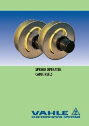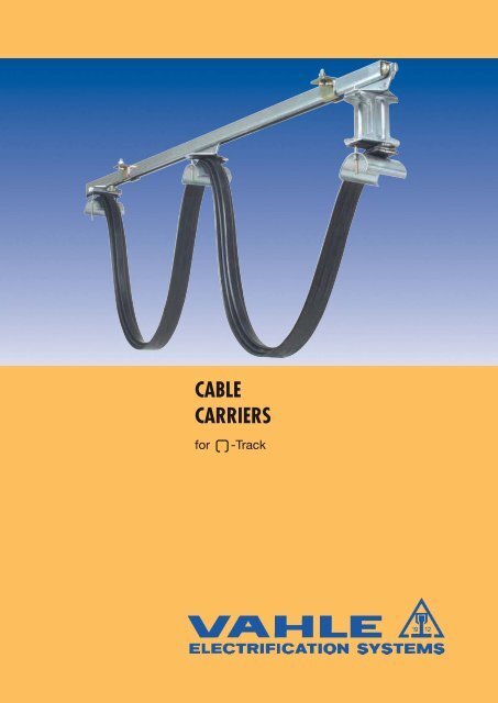
Cable Carriers for 'C'-Tracks - VAHLE, Inc
Cable Carriers for 'C'-Tracks - VAHLE, Inc
Cable Carriers for 'C'-Tracks - VAHLE, Inc

You also want an ePaper? Increase the reach of your titles
YUMPU automatically turns print PDFs into web optimized ePapers that Google loves.
S 1 TRACK AND ACCESSORIESacidproofStainlessTrackHanger underhungType S1 S1A S1-EOrder-No. -in 6 m sections 312 946 312 966 312 956Order-No. -in 4 m sections 312 944 312 964 312 954Order-No. -surcharge <strong>for</strong> curves 310 470 - 312 472<strong>for</strong> Carrier type WS 1, WST 1 WST 1-EThickness 2 mm 1,5 mm 2 mmMaterial steel, galvanized V 4 A, stainless steelSupply lengths6 m and 4 mStandard support spacing As per Page 47, in straight system max. 2 m, in curves max.1m.Moment of inertia Jx 2,42 cm 4 1,9 cm 4 2,42 cm 4Section modulus Wx 1,45 cm 3 1,1 cm 3 1,45 cm 3Weight 1,550 kg/m 1,190 kg/m 1,550 kg/mThe delivery of curves is possible (excluded S1A).Please send us your inquiry.Max. system length: 100 mFixpoint hangerTypeFAS 1Order-No. 310 500Materialsteel, galvanizedWeight0,160 kgFor up to 30 m runs only.1 pair of bolts M 8 x 25, Order-No. 310 510 to be orderedseparately <strong>for</strong> each hanger or provided by customer.Sliding Fixpoint Sliding FixpointType hanger hanger hanger hangerADS 1 (1) FDS 1 ADS 1-E (1) FDS 1-EOrder-No. 310 370 310 430 312 393 312 394Material steel, galvanized V 4 A, stainless steelWeight 0,200 kg 0,210 kg 0,200 kg 0,210 kgSlidingFixpointType hanger hangerABS 1 (1) FBS 1Order-No. 312 863 312 864Materialsteel, galvanizedWeight 0,226 kg 0,234 kgHanger underhung <strong>for</strong> HK supportTypeFixpoint hangerFAKS 1 (clamp)Order-No. 310 590Materialsteel, galvanizedWeight0,260 kgFor up to 30 m runs only.Sliding Fixpoint Sliding FixpointType hanger hanger hanger hangerAKS 1 (1) FKS 1 AKS 1-E (1) FKS 1-EOrder-No. 310 380 310 450 312 457 312 458Material steel, galvanized V 4 A, stainless steelWeight 0,260 kg 0,270 kg 0,260 kg 0,270 kg(1)For systems with control-carriers use fixpoint hangers only.5
S 1 ACCESSORIESacidprooStainlessBumper stopTyp PS 1 PS 1 G PS 1-EOrder-No. 310 300 310 360 312 395Material steel, galvanized steel, galvanized V 4 A, stainless steelWeight 0,080 kg 0,100 kg 0,080 kgBumper stop25Type PS 1-1Order-No. 312 605Materialsteel, galvanizedWeight0,063 kgFlat Nut w/bolt and washerTyp M 8 x 20 M 8 x 20 EOrder-No. 312 600 313 454Material steel, galvanized V 4 A, stainless steelWeight 0,044 kg 0,044 kgClamps <strong>for</strong> round cables and hosesHS 1D (cable Ø)profile S1LK - S1InstallationØ15Ø12Installation position30TypeMaterialWeight Dim. D Orderkgmm No.Ø11Ø770,541HS 1-D 9 stainless 0,010 8 - 10 312 667HS 1-D 16 steel 0,011 15 - 20 312 666LK-S1 PVC 0,010 7 - 15 313 3797
S 1 CABLE CARRIERS AND ACCESSORIES– Polyamid type –Engineering DataTypeWheelsMaterialMax. cable load<strong>for</strong> corrosive sites<strong>Cable</strong> <strong>Carriers</strong> <strong>for</strong> flat<strong>for</strong>m cablesTypewheelsWS 1 F (not suitable <strong>for</strong> curved track)A) Polyamid rollers on bushed bearing; axle galvanizedMaterial: polyamid, Travelling speed: ca. 50 m/min.B) Polyamid rollers on stainless bushed bearingMaterial: polyamid, Travelling speed: ca. 50 m/min.C) Polyamid rollers with ball bearing; inner race hardened, galvanizedouter race Polyamid, Travelling speed: ca. 60 m/min.D) hardened and galvanized steel rollers with precision ball bearing,sealed against dust and splash water.Temperature resistance: lub. grease of wheels: –30 °C to + 125 °CTravelling speed: ca. 80 m/min.Carrier body: PolyamidSupport saddle: PolyamidHardware: galvanizedTemperature resistance: – 30 °C to + 100 °Cmax. 8 kg per Carrier with roller Amax. 10 kg per Carrier with roller B + Cmax. 16 kg per Carrier with roller Duse system S 1-E or K1max. thicknessofindividualcable mmmax.clampingcapacity mmheight x widthA B C D E G HmmWeightkgOrderNo. . (1)withpatentednut Order-No. (2)WS 1 F/ 85 G A 0,120 310 958 312 686WS 1 F/ 85 K B8 17 x 65 85 55 25 50 37 71 900,130 310 180 312 687WS 1 F/ 85 KL C 0,130 310 320 312 688WS 1 F/ 85 D 0,190 310 070 312 689WS 1 F/125-50 G A 0,150 312 759 312 760WS 1 F/125-50 K B8 37 x 65 125 95 40 50 37 71 900,160 312 761 312 762WS 1 F/125-50 KL C 0,160 312 763 312 764WS 1 F/125-50 D 0,220 312 765 312 766WS 1 F/125-80 G A 0,170 312 767 312 768WS 1 F/125-80 K B10 22 x 65 125 95 40 80 37 71 900,180 312 769 312 770WS 1 F/125-80 KL C 0,180 312 771 312 772WS 1 F/125-80 D 0,240 312 773 312 774L M= 63125953675123Ø2525765Lead <strong>Carriers</strong> <strong>for</strong> flat<strong>for</strong>m cableswheelsType <strong>for</strong> Weight Order patentedCarrier type kg No. (1) nut Order-No. (2)withMS 1 F/125-50 G A WS 1 F/ 85 G, WS 1 F/125-50 G 0,140 313 281 313 285MS 1 F/125-50 K B WS 1 F/ 85 (K, G), WS 1 F/125-50 (K, G) 0,144 313 280 313 284MS 1 F/125-50 KL C WS 1 F/ 85 (KL, K, G), WS 1 F/125-50 (KL,K,G) 0,158 313 279 313 283MS 1 F/125-50 D WS 1 F/85 (all types) WS 1 F/125-50 (all types) 0,200 313 278 313 282MS 1 F/125-80 G A WS 1 F/125-80 G 0,156 313 293 313 297MS 1 F/125-80 K B WS 1 F/125-80 (K, G) 0,162 313 292 313 296MS 1 F/125-80 KL C WS 1 F/125-80 (KL, K, G) 0,174 313 291 313 295MS 1 F/125-80 D WS 1 F/125-80 (all types) 0,216 313 290 313 294L E= 100Bumper stopTrack Clamps <strong>for</strong> flat<strong>for</strong>m cablesType <strong>for</strong> Weight OrderCarrier type kg No. (1)ES 1 F/ 85 WS 1 F/ 85 (all types)0,220 313 303 EST 1-2 F/ 85-PM 313 304WS 1 F/125-50 (all types)ES 1 F/125-80 WS 1 F/125-80 (all types) 0,240 313 307 EST 1-2 F/125-PM 313 308Bumper stop PS 1, PS 1-1, PS 1 G to be ordered separately.with patented nutTypeOrder.-No.45Track Clamp with bumper <strong>for</strong> flat<strong>for</strong>m cablesBumper stopType <strong>for</strong> Weight Order-Carrier type kg No. (1)with patented nutTypeOrder-No.EP S1 F/ 85 WS 1 F/ 85 (all types) 0,230 313 305 EPST 1-2 F/85-PM 313 30610(1)hex. nut type(2)with patented quick-set nut use suffix PM, e.g. WS 1 F/85-PM <strong>for</strong> Order-No. 312 689
S 1 CABLE CARRIERS AND ACCESSORIES– Polyamid swivel type –Engineering DataTypeWheelsMaterialMax. cable load<strong>for</strong> corrosive sitesWS 1 R (not suitable <strong>for</strong> curved track)A) Polyamid rollers on bushed bearing; axle galvanizedMaterial: polyamid, Travelling speed: ca. 50 m/min.B) Polyamid rollers on stainless bushed bearingMaterial: polyamid, Travelling speed: ca. 50 m/min.n.C) Polyamid rollers with ball bearing; inner race hardened, galvanizedouter race Polyamid, Travelling speed: ca. 60 m/min.D) hardened and galvanized steel rollers with precision ball bearing,sealed against dust and splash waterTemperature resistance: lub. grease of wheels: –30 °C to + 125 °CTravelling speed: ca. 80 m/min.Carrier body: PolyamidSupport saddle: PolyamidHardware: galvanizedTemperature resistance: – 30 °C to + 100 °Cmax. 8 kg per Carrier with roller Amax. 10 kg per Carrier with roller B + Cmax. 16 kg per Carrier with roller Duse system S 1-E or K1<strong>Cable</strong> <strong>Carriers</strong> <strong>for</strong> round cables and hoses<strong>Cable</strong> ØType <strong>Cable</strong> Wheels A B C D E F G Weight Order-Ø mmkg No.WS 1 R/85 G A 0,260 313 3325 mmWS 1 R/85 K B 0,270 312 486toWS 1 R/85 KL 38 mm C 85 55 25 25 85 36 99 0,280 312 487WS 1 R/85 D 0,320 312 4851259536Ø25257Lead <strong>Carriers</strong> <strong>for</strong> round cables and hoses7512365L MType <strong>for</strong> LM Weight Order-Carrier type kg No.MS 1 R/125 G WS 1 R/85 G 63 0,284 313 289MS 1 R/125 K WS 1 R/85 (K, G) 63 0,288 313 288MS 1 R/125 KL WS 1 R/85 (KL, K, G) 63 0,302 313 287MS 1 R/125 WS 1 R/85 (all types) 63 0,304 313 28645Track Clamp <strong>for</strong> round cables and hosesBumper stopType <strong>for</strong> Weight Order-Carrier type kg No.EPST 1-2 R WS 1 R (all types) 0,346 313 322Support Saddle <strong>for</strong> round cables and hoses<strong>for</strong> additional tiersType <strong>for</strong> Weight Order-Carrier type kg No.LAR WS 1 R (all types) 0,110 312 50011
S 1 CABLE CARRIERS – Steel type –acidproofStainlessSupport saddlewith hex. nutEngineering DataTypeWheelsMaterialMax. cable loadDepth of cable loop<strong>for</strong> corrosive sitesSupport saddlewith patented nutWST 1 Fball bearings sealed against dust and splash waterhardened, galvanizedTemperature resistance Lub. grease of wheels: –30 °C to + 125 °CTravelling speed: ca. 80 m/min.Carrier body: steel, galvanizedSupport saddle: steel, galvanizedD = 140 – aluminiumBumper: NeopreneHardware: galvanizedTemperature resistance: – 30 °C to + 100 °Cmax. 22 kg per carrierin curves max. 0,3 x track radius,consider tension reliefuse system S 1-E or K 1with patented nutSupport saddlePolyamidWST 1 F-Esealed ball bearingsstainless steel, V 4 A–30 °C to + 150 °Cca. 80 m/min.WST 1 F K-EPolyamid rollerson bushed bearingca. 50 m/min.V 4 A, stainless steelV 4 A, stainless steel–––––NeopreneV 4 A, stainless steel– 30 °C to + 80 °Cmax. 12 kg per carrier max. 8 kg per carriernot in curves<strong>Cable</strong> <strong>Carriers</strong> <strong>for</strong> flat<strong>for</strong>m cablesBumper typeTypemax.thickn. ofindividualcable mmmax. clampingcapacity inmmheight x widthA B Ø D G HmmWeightkgOrder-No.withpatentednut Order-No (2 )WST 1 F/ 85 (1) 17 x 65 8543 850,360 312 000 312 789 WST 1 F/ 85 E (1) 312 381 WST 1 F/ 85 K-E (1) 313 218WST 1 F/ 85 P829 x 65 110500,370 312 010 312 790 WST 1 F/ 85P-E 312 387 WST 1 F/ 85 KP-E 313 219WST 1 F/125-50 (1) 37 x 65 125 0,460 312 533 312 791 WST 1 F/125-50-E (1) 312 519 WST 1 F/125-50K-E (1) 313 221WST 1 F/125-50 P 50 x 65 150 0,470 312 534 312 792 WST 1 F/125-50P-E 312 520 WST 1 F/125-50KP-E 313 22280WST 1 F/125 (1) 9722 x 65 125 0,520 312 020 312 793 WST 1 F/125-E (1) 312 384 WST 1 F/125 K-E (1) 313 2231080WST 1 F/125 P 34 x 65 150 0,530 312 030 312 794 WST 1 F/125P-E 312 388 WST 1 F/125 KP-E 313 224WST 1 F/150-50 (1) 850 x 65 150500,480 312 537 312 795 WST 1 F/150-50-E (1) 312 560 WST 1 F/150-50 K-E (1) 313 225WST 1 F/150-50 P 62 x 65 175 0,490 312 538 312 796 WST 1 F/150-50P-E 312 561 WST 1 F/150-50 KP-E 313 226WST 1 F/150-80 (1) 1035 x 65 150105 80 710,540 312 539 312 797 WST 1 F/150-80-E (1) 312 562 WST 1 F/150-80 K-E (1) 313 227WST 1 F/150-80 P 47 x 65 175 0,550 312 540 312 798 WST 1 F/150-80P-E 312 563 WST 1 F/150-80 KP-E 313 228WST 1 F/150 (1) 25 x 65 150 0,580 312 040 WST 1 F/150-E (1) 312 564 WST 1 F/150 K-E 313 229WST 1 F/150 P1237 x 65 175100 850,590 312 050 WST 1 F/150P-E 312 565 WST 1 F/150 KP-E 313 230WST 1 F/200-100 (1) 50 x 65 200 0,680 312 831WST 1 F/200-100 P 62 x 65 2251550,700 312 832WST 1 F/200-140 (1) 30 x 65 200 0,670 312 833WST 1 F/200-140 P1442 x 65 2251400,680 312 834WST 1 F/250-140 (1) 55 x 65 2502050,740 312 835WST 1 F/250-140 P 67 x 65 275 0,750 312 836TypeOrder-No.TypeOrder-No.12(1)without Bumper(2)with patented quick-set nut use suffix PM, e.g. WST 1 F/85 PM <strong>for</strong> Order-No. 312 789
S 1 LEAD CARRIERSAND TRACK CLAMPS – Steel type –acidproofStainlessBumper typeL MLead <strong>Carriers</strong> <strong>for</strong> flat<strong>for</strong>m cablesType<strong>for</strong>Carrier typeLMAmmWeightkgOrder-No.withpatented nutOrder-No. (2)MST 1 F/ 85 (1) WST 1 F/ 85 43 85 0,730 312 080 312 799 MST 1 F/ 85-E (1) 312 382 MST 1 F/ 85 K-E (1) 313 231MST 1 F/ 85 P WST 1 F/ 85 P 55 110 0,740 312 090 312 800 MST 1 F/ 85 P-E 312 389 MST 1 F/ 85 KP-E 313 232MST 1 F/125-50 (1) WST 1 F/125-50 63 125 0,830 312 535 312 801 MST 1 F/125-50-E (1) 312 521 MST 1 F/125-50 K-E (1) 313 233MST 1 F/125-50 P WST 1 F/125-50 P 75 150 0,840 312 536 312 802 MST 1 F/125-50 P-E 312 522 MST 1 F/125-50 KP-E 313 234MST 1 F/125 (1) WST 1 F/125 63 125 0,880 312 100 312 803 MST 1 F/125-E (1) 312 385 MST 1 F/125 K-E (1) 313 235MST 1 F/125 P WST 1 F/125 P 75 150 0,890 312 110 312 804 MST 1 F/125 P-E 312 390 MST 1 F/125 KP-E 313 236MST 1 F/150-50 (1) WST 1 F/150-50 75 150 0,850 312 541 312 805 MST 1 F/150-50-E (1) 312 566 MST 1 F/150-50 K-E (1) 313 237MST 1 F/150-50 P WST 1 F/150-50 P 88 175 0,860 312 542 312 806 MST 1 F/150-50 P-E 312 567 MST 1 F/150-50 KP-E 313 238MST 1 F/150-80 (1) WST 1 F/150-80 75 150 0,900 312 543 312 807 MST 1 F/150-80-E (1) 312 568 MST 1 F/150-80 K-E (1) 313 239MST 1 F/150-80 P WST 1 F/150-80 P 88 175 0,910 312 544 312 808 MST 1 F/150-80 P-E 312 569 MST 1 F/150-80 KP-E 313 240MST 1 F/150 (1) WST 1 F/150 75 150 0,950 312 120 MST 1 F/150-E (1) 312 570 MST 1 F/150 K-E (1) 313 241MST 1 F/150 P WST 1 F/150 P 88 175 0,960 312 130 MST 1 F/150 P-E 312 571 MST 1 F/150 KP-E 313 242MST 1 F/200-100 (1) WST 1 F/200-100 100 200 1,050 312 837MST 1 F/200-100 P WST 1 F/200-100 P 113 225 1,070 312 838MST 1 F/200-140 (1) WST 1 F/200-140 100 200 1,030 312 839MST 1 F/200-140 P WST 1 F/200-140 P 113 225 1,040 312 840MST 1 F/250-140 (1) WST 1 F/250-140 125 250 1,110 312 841MST 1 F/250-140 P WST 1 F/250-140 P 138 275 1,120 312 842TypeOrder-No.TypeOrder-No.Track Clamps <strong>for</strong> flat<strong>for</strong>m cablesTypeEST 1-2 F/ 85EST 1-2 F/125EST 1-2 F/150EST 1-2 F/100-2EST 1-2 F/140-2<strong>for</strong>Carrier typeWST 1 F/ 85 (P)WST 1 F/125-50 (P)WST 1 F/150-50 (P)WST 1 F/125 (P)WST 1 F/150-80 (P)WST 1 F/150 (P)WST 1 F/200-100 (P)WST 1 F/200-140 (P)WST 1 F/250-140 (P)LEmm140165WeightkgOrder-No.withpatented nutOrder-No. (2)TypeOrder-No.0,290 313 315 313 304 EST 1-2 F/ 85-E 312 3830,370 313 316 313 308 EST 1-2 F/125-E 312 3860,410 313 317 EST 1-2 F/150-E 312 5720,410 313 3180,430 313 319L EBumper stopBumper stop PS 1, PS 1-1, PS 1 G or PS 1-E to be ordered separately.<strong>VAHLE</strong> Festoon feedingrobotic production.(1)without Bumper(2) with patented quick-set nut use suffix PM13
LS 1 CABLE CARRIERSAND ACCESSORIES – Steel type –Engineering DataTypeWheelsMaterialfMax. cable loadDepth of cable loop<strong>for</strong> corrosive sitesWST 1 Fball bearings sealed against dust and splash waterhardened, galvanizedTemperature resistance Lub. grease of wheels: –30 °C to + 125 °CTravelling speed: ca. 80 m/min.Carrier body: steel, galvanizedSupport saddle: steel, galvanized; D = 100 & 140 aluminiumBumper: NeopreneHardware: galvanizedTemperature resistance: – 30 °C to + 100 °Cmax. 22 kg per carrierin curves max. 0,3 x track radius,consider tension reliefuse system S 1-E or K 1<strong>Cable</strong> <strong>Carriers</strong> <strong>for</strong> flat<strong>for</strong>m cablesBumper typeTypemax.thickn. ofindividualcable mmmax. clampingcapacity inmmheigth x widthWST 1 F/125-50 B (1) 37 x 100 125 0,630 312 902850WST 1 F/125-50 B P 50 x 100 150 0,640 312 90380 110 134WST 1 F/125-80 B (1) 22 x 100 125 0,720 312 9041080WST 1 F/125-80 B P 34 x 100 150 0,730 312 905WST 1 F/150-100 B 160 (1) 25 x 130 150 0,750 312 845105WST 1 F/150-100 B 160 P 37 x 130 175 0,760 312 846WST 1 F/200-100 B 160 (1)) 1210050 x 130 200 0,840 312 847WST 1 F/200-100 B 160 P 62 x 130 225 0,850 312 848155WST 1 F/200-140 B 160 (1) 136 16030 x 130 200 0,970 312 849WST 1 F/200-140 B 160 P 42 x 130 225 0,980 312 85014140WST 1 F/250-140 B 160 (1) 55 x 130 250 1,040 312 851205WST 1 F/250-140 B 160 P 67 x 130 275 1,050 312 852ABØ DmmGHWeightkgOrder-No.Lead <strong>Carriers</strong> <strong>for</strong> flat<strong>for</strong>m cablesBumper typeType<strong>for</strong>Carrier typeAmmWeightkgOrder-No.MST 1 F/125-50 B (1) WST 1 F/125-50 B 125 1,000 312 906MST 1 F/125-50 B P WST 1 F/125-50 B P 150 1,010 312 907MST 1 F/125-80 B (1) WST 1 F/125-80 B 125 1,080 312 908MST 1 F/125-80 B P WST 1 F/125-80 B P 150 1,090 312 909MST 1 F/150-100 B 160 (1) WST 1 F/150-100 B 160 150 1,100 312 853MST 1 F/150-100 B 160 P WST 1 F/150-100 B 160 P 175 1,110 312 854MST 1 F/200-100 B 160 (1) WST 1 F/200-100 B 160 200 1,190 312 855MST 1 F/200-100 B 160 P WST 1 F/200-100 B 160 P 225 1,200 312 856MST 1 F/200-140 B 160 (1) WST 1 F/200-140 B 160 200 1,330 312 857MST 1 F/200-140 B 160 P WST 1 F/200-140 B 160 P 225 1,340 312 858MST 1 F/250-140 B 160 (1) WST 1 F/250-140 B 160 250 1,390 312 859MST 1 F/250-140 B 160 P WST 1 F/250-140 B 160 P 275 1,400 312 860L ETrack Clamps <strong>for</strong> flat<strong>for</strong>m cablesBumper stopBumper stop PS 1, PS 1-1, PS 1 Gto be ordered separately.Type<strong>for</strong>Carrier typeLEmmWeightkgOrder-No.EST 1-2 F/125-50 B WST 1 F/125-50 B (P) 0,470 313 313140EST 1-2 F/125-80 BWST 1 F/125-80 B (P)0,520 313 314WST 1 F/150-100 B 160 (P) 140EST 1-2 F/100 B 160 WST 1 F/200-100 B 160 (P) 155 0,560 313 311WST 1 F/200-140 B 160 (P) 1550,700EST 1-2 F/140 B 160 WST 1 F/250-140 B 160 (P) 180 0,700313 31214(1) without Bumper
S 1 CABLE CARRIERSAND ACCESSORIES – Steel type –acidproofStainlessEngineering DataBumper typeTypeWheelsMaterialMax. cable loadDepth of cable loop<strong>for</strong> corrosive sitesWST 1 Rball bearings sealed against dust and splashwater hardened, galvanizedTemperature resistance: Lub. grease ofwheels: –30 °C to + 125 °CTravelling speed: ca. 80 m/min.Carrier body: steel, galvanizedSupport saddle: PolyamidBumper: NeopreneHardware: galvanizedTemperature resistance: – 30 °C to + 100 °Cmax. 22 kg per carrierin curves max. 0,3 x track radius;consider tension reliefuse system S 1-E or K 1WST 1 R-Esealed ball bearingstainless steel, V 4 A–30 °C to + 150 °Cca. 80 m/min.V 4 A, stainless steelPolypropyleneNeopreneV 4 A, stainless steel– 10 °C to + 80 °Cmax. 12 kg per carrierWST 1 RK-EPolyamid rollers onbushed bearingca. 50 m/min.max. 8 kg per carriernot in curves<strong>Cable</strong> <strong>Carriers</strong> <strong>for</strong> round cables and hoses<strong>Cable</strong> Ø<strong>Cable</strong>- A B C D E F G Weight Order-Order-Order-TypeTypeTypeØmmkg No.No.No.WST 1 R/ 85 (1) 85 0,430 312 491 WST 1 R/ 85-E (1) 312 523 WST 1 R/ 85 K-E 313 243WST 1 R/ 85 P 5 mm 110 43 24 25 85 36 99 0,460 312 492 WST 1 R/ 85 P-E 312 524 WST 1 R/ 85 KP-E 313 244WST 1 R/125 (1) to38 mm125 0,540 312 493 WST 1 R/125-E (1) 312 525 WST 1 R/125 K-E 313 245WST 1 R/125 P 150 80 24 25 97 36 99 0,570 312 494 WST 1 R/125 P-E 312 526 WST 1 R/125 KP-E 313 246Lead <strong>Carriers</strong> <strong>for</strong> round cables and hosesL M<strong>for</strong>LMTypeA C D H Weight Order-Order-Order-Carrier typeTypeTypemmkg No.No.No.MST 1 R/ 85 (1) WST 1 R/ 85 43 85 0,780 312 495 MST 1 R/ 85-E (1) 312 527 MST 1 R/ 85 K-E 313 247MST 1 R/ 85 P WST 1 R/ 85 P 55 110 0,810 312 496 MST 1 R/ 85 P-E 312 528 MST 1 R/ 85 KP-E 313 24824 25 80MST 1 R/125 (1) WST 1 R/125 63 125 0,890 312 497 MST 1 R/125-E (1) 312 529 MST 1 R/125 K-E 313 249MST 1 R/125 P WST 1 R/125 P 75 150 0,920 312 498 MST 1 R/125 P-E 312 530 MST 1 R/125 KP-E 313 250Track Clamp <strong>for</strong> round cables and hosesL EBumper stopType <strong>for</strong> LE Weight Order- Type Order-Carrier type mm kg No. No.EST 1-2 R WST 1 R (all types) 100 0,340 313 321 EST 1 R-E 312 531Bumper stop PS 1, PS 1-1, PS 1 G, PS 1-E to be ordered separately.Support Saddle <strong>for</strong> round cables and hoses<strong>for</strong> additional tiersType <strong>for</strong> Weight Order- Type Order-Carrier type kg No. No.LAR WST 1 R (alle Typen) 0,110 312 500 LAR-E 312 532(1)without Bumper15
S 1 CABLE CARRIERS AND ACCESSORIES– Steel type –Engineering DataTypeWheelsMaterialMax. cable load<strong>for</strong> corrosive sitesWST 1 R/250, WST 1 R/250 Pball bearings sealed against dust and splash waterhardened, galvanizedTemperature resistance Lub. grease of wheels: –30 °C to + 125 °CTravelling speed: ca. 80 m/min.Carrier body: steel, galvanized<strong>Cable</strong>-loop: PolyamidSupport saddle: PolyamidHardware: galvanizedTemperature resistance: – 30 °C to + 100 °Cmax. 22 kg per carrier WST 1 R/250 (P)use system S 1-E or K 1Bumper type<strong>Cable</strong> <strong>Carriers</strong> <strong>for</strong> round cables and hosesWST 1 R/250 (P)Type max. cable-Ø mm Weight kg Order-No.WST 1 R/250 (1) 0,660 312 0603 x Ø 20WST 1 R/250 P 0,690 312 070Bumper typeLead <strong>Carriers</strong> <strong>for</strong> round cables and hosesSupport saddle same as <strong>for</strong> cable carriersL MMST 1 R/250 (1) WST 1 R/250 125 250 1,000 312 140Type <strong>for</strong> LM A Weight Order-Carrier type mm kg No.MST 1 R/250 P WST 1 R/250 P 125 275 1,030 312 150Track Clamp <strong>for</strong> round cables and hosesSupport saddle same as <strong>for</strong> cable carriersL EBumper stopBumper stop PS 1, PS 1-1, PS 1 Gto be ordered separately.Type <strong>for</strong> LE Weight Order-Carrier type mm kg No.ES 1 R/250WST 1 R/250 165WST 1 R/250 P 1780,298 313 32016 (1) without Bumper
S 1 CABLE CARRIERS AND ACCESSORIES– Steel type –Engineering DataTypeWheelsMaterialMax. cable load<strong>for</strong> corrosive sitesWR 1-Sch, WST 1-Schball bearings sealed against dust and splash waterhardened, galvanizedTemperature resistance Lub. grease of wheels: –30 °C to + 125 °CTravelling speed: ca. 80 m/min.Carrier body: steel, galvanizedS-Hook: steel, galvanized<strong>Cable</strong>-loop: PolyamidHardware: galvanizedTemperature resistance: – 30 °C to + 100 °Cmax. 10 kg per carrier WR 1-Schmax. 20 kg per carrier WST 1-Schuse system S 1-E or K 1<strong>Cable</strong> <strong>Carriers</strong> <strong>for</strong> round cables and hosesWR 1-Sch WST 1-Sch Type Ø D L Weight Ordermmmm kg No.WR 1-Sch/ 80 80 210 0,100 312 900WR 1-Sch/160 160 290 0,110 312 901WST 1-Sch/ 80 80 240 0,270 312 875WST 1-Sch/160 160 320 0,280 312 876Installation in<strong>for</strong>mation:1. prepare ribbon ends as shown.2. pull all ends thru flap.3. <strong>for</strong>m a loop.4. attach flap to S-hook!Lead <strong>Carriers</strong> <strong>for</strong> round cables and hosesL MType <strong>for</strong> LM Weight Order-Carrier type kg No.MST 1-Sch/ 80MST 1-Sch/160WR 1-Sch/ 80WST 1-Sch/ 80WR 1-Sch/160WST 1-Sch/16043 0,680 312 87743 0,690 312 878L ETrack Clamps <strong>for</strong> round cables and hosesBumper stop PS 1, PS 1-1 or PS 1 Gto be ordered separately.Type <strong>for</strong> LE Weight Order-Carrier type kg No.EST 1-2-Sch/ 80EST 1-2-Sch/160WR 1-Sch/ 80WST 1-Sch/ 80WR 1-Sch/160WST 1-Sch/160110 0,140 312 879110 0,150 312 88017
S 1 CONTROL CARRIERAND ACCESSORIESacidproofStainlessControl <strong>Carriers</strong> with multipole plug-inconduit coverM 40x1,5Type (1) plug-in-device Weight Order-DIN 43652 kg No.ST-ST 1/16 M 16pole 2,100 313 371ST-ST 1/24 M 24pole 2,300 313 370Design <strong>for</strong> round cable clamp ST-ST 1 RST-ST 1 R/16 M 16pole 2,200 313 373ST-ST 1 R/24 M 24pole 2,400 313 372Design:Carrier body: steel, galvanized Support bar: aluminiumWheels: steel ball bearings Plug: cast iron<strong>Cable</strong> glands <strong>for</strong> 16-poles <strong>Cable</strong> glands <strong>for</strong> 24-polesA-Seite: M 40 x 1,5 A-Seite: M 40 x 1,5B-Seite: M 32 x 1,5 B-Seite: M 40 x 1,5Max. cable load: 25 kgTemperature resistance: – 30 °C to + 100 °CControl <strong>Carriers</strong> without BrakeType (1) D E F G Weight kg Order-No. Type (1) Order-No.mmST-ST 1/A 1 190 150 38 100 2,900 312 695 ST-ST 1-E 316 332ST-ST 1/A 2 280 200 62 140 4,300 312 694 – –Design <strong>for</strong> round cable clamp ST-ST 1 RST-ST 1 R/A 1 190 150 38 100 3,000 312 817 ST-ST 1 R-E 312 819ST-ST 1 R/A 2 280 200 62 140 4,400 312 818 – –Design:Carrier body: steel, galvanized Support bar: aluminiumWheels: steel ball bearings Plug: PVCMax. load: 25 kgsService temperature: -30 °C upto + 100 °CAttention: The connection box must be earthed with aprotective earth conductor terminal Type EK 2.5 N PA!ST-ST 1/A 1 ST-ST 1/A 2ST-ST 1 R/A 1 ST-ST 1 R/A 2ST-ST 1-E & ST-ST 1 R-Emax. max. - max. max.<strong>Cable</strong> glands number number <strong>Cable</strong> glands number numberA-Side B-Side A-Side B-SideM 20 x 1,5 6 2 M 20 x 1,5 12 6M 25 x 1,5 5 1 M 25 x 1,5 10 6M 32 x 1,5 3 1 M 32 x 1,5 8 4M 40 x 1,5 2 1 M 40 x 1,5 4 1M 50 x 1,5 2 – M 50 x 1,5 3 1M 63 x 1,5 2 – M 63 x 1,5 3 1Max. length of Terminal Block A 1 = 130mmA 2 = 220 mmBrake spring <strong>for</strong> Control Carrier ST-ST 1The braking device can be installed as an option.Type Material Weight kg Order-No.BF 1 stainless steel 0,007 310 86018(1) For systems with control carriers use fixpoint hangers only. Support distance max. 1,5 m.<strong>Cable</strong> glands and terminal clamps <strong>for</strong> A1 & A2 boxes to be ordered separately (see cat. 8L).Control carriers with larger terminal box on request..
S 1 ACCESSORIES FOR CONTROL CARRIERSacidproofStainlessBrake <strong>for</strong> Control CarrierType Weight Order-No.kgBS 1 1,740 312 698Design:Carrier: Steel, galvanizedWheels: Steel ball bearingsBrake <strong>for</strong> Control Carrier with AC magnet (WM)Type Weight Order-No.kgBS 1-WM 2,900 312 699Connected load230 V/50 HZ, 0,3 A100 % EDTow Rope and Grip <strong>for</strong> Brake BS 1TypeStandard lengthmmWeightkgOrder-No.ZSB 5000 0,250 310 850Scope of delivery: hand grip, rope, rope thimble and clamp.19
S 2 TRACK AND ACCESSORIESacidproofSliding- Fixpoint-Type hanger hangerAS 2 (1) FS 2Order-No. 315 030 315 040Materialsteel, galvanizedWeight 0,470 kg 0,480 kgStainlessTrack Type S 2 S 2-EOrder-No.,in 6 m sections 316 636 316 646Order-No., in 4 m sections 316 634 316 644Order-No. surcharge <strong>for</strong> curves 310 480 315 372<strong>for</strong> <strong>Carriers</strong> type WS 2 and WST 2 WST 2-EMaterial steel, galvanized V 4 ASupply lengths 6 m and 4 m in straight system max. 2.5 m,Standard support spacing see page 48,in curves max. 1 m,Moment of inertia Jx 6,7 cm 4 6,7 cm 4Section modulus Wx 3,1 cm 3 3,1 cm 3Weight 2,490 kg/m 2,490 kg/mHorizontal Curves are ready available. Consult factory <strong>for</strong> specials.Hanger underhungSliding- Fixpoint- Sliding- Fixpoint-Type hanger hanger hanger hangerADS 2 (1) FDS 2 ADS 2-E (1) FDS 2-EOrder-No. 315 200 315 210 315 357 315 356Material steel, galvanized V 4 A, stainless steelWeight 0,310 kg 0,320 kg 0,310 kg 0,320 kgSliding- Fixpoint-Typ hanger hangerABS 2 (1) FBS 2Order-No. 315 140 315 150Materialsteel, galvanizedWeight 0,370 kg 0,380 kgHanger underhung <strong>for</strong> HK supportSliding- Fixpoint- Sliding- Fixpoint-Type hanger hanger hanger hangerAKS 2 (1) FKS 2 AKS 2-E (1) FKS 2-EOrder-No. 315 220 315 230 315 379 315 380Material steel, galvanized V 4 A, stainless steelWeight 0,490 kg 0,500 kg 0,490 kg 0,500 kgHanger lateralJoint Clamp upto 100 m system lengthType VS 2 VS 2-EOrder-No. 315 050 315 355Material steel, galvanized V 4 A, stainless steelWeight 0,680 kg 0,680 kg20(1) For systems with control carriers use fixpoint hangers only.
S 2 ACCESSORIESacidproofStainlessJoint Clamp, lock type (Patent pending) from 100 m system lenghtType VS 2-FOrder-No. 316 522Materialsteel, galvanizedWeight0,680 kgEnd CapType K 40Order-No. 316 449MaterialpolyethyleneWeight0,009 kgBumper stop60301560303030M8M8PS 2-1 (E)PS 2-1 GType PS 2-1 PS 2-1 G PS 2-1 EOrder-No. 317 000 317 001 317 002Material steel, galvanized steel, galvanized V 4 A, stainless steelWeight 0,220 kg 0,250 kg 0,220 kgFlat nut w/bolt and washerType M 8 x 20Order-No. 312 600MaterialStahl, verzinktWeight0,044 kg21
S 2 ACCESSORIESacidproofStainlessStandard BracketsChoose dim. A perlocal requirements andmake sure that hoistwheels have enoughclearance.Select next larger sizebracket when your-Beam dim. B ismore than 210 mmand refer to page 23<strong>for</strong> heavy dutybrackets.Type Material Weight A (adjustable) L max Order-No. Type Mat. Order-No.kg mm mm B mmHK 200 0,980 200 400 210 (1) 310 220 HK 200-E 312 510HK 300 1,130 300 500 210 (1) stainl.steel310 230 HK 300-E 312 511steelHK 400 galvanized 1,290 400 600 210 (1) 310 240 HK 400-E V 4 A 312 512HK 500 1,430 500 700 210 (1) 310 250 HK 500-E 312 513Scope of supply: 1 pair of claws and rail short length S1.Hangers AKS 2 and FKS 2 to be ordered separately.Bracket Bars <strong>for</strong> HKType Material Weight L Order-No. Type Mat. Order-No.kgmmS 1-400 0,620 400 310 600 S 1E-400 312 515S 1-500 steelstainl.0,780 500 310 610 S 1E-500 312 516S 1-600 galvanizedsteel0,930 600 310 620 S 1E-600V 4 A312 517S 1-700 1,090 700 310 630 S 1E-700 312 518Claws <strong>for</strong> HKType SP 0-20 SP 0-20-EOrder-No. 310 390 312 514Material steel, galvanized V 4 A, stainless steelWeight 0,200 kg 0,200 kgRange area 0-20 mmFlat nut M 8 E stainlessFlat nut M 8 separately available.separately available.Order-No. 310 955 Order-No. 312 545Support Attachment <strong>for</strong> HKType AH 1Order-No. 310 400MaterialsteelWeight0,460 kgBracket bar sections and hangers to be ordered separately..22(1) In case of a bigger beam width the next bigger HK have to be used.
S 2 ACCESSORIESacidproofStainlessBracket Bars <strong>for</strong> HK heavy dutyThe track sections are provided with drillings to fix the support hangers at the bottom flange of the track profile.Type Material Weight Dim. L Order-No. Type Mat. Order-No.kgmmS 2- 400 0,996 400 315 402 S 2E- 400 316 513S 2- 500 1,245 500 315 403 S 2E- 500 316 514S 2- 600 1,494 600 315 404 S 2E- 600 316 515S 2- 700 1,743 700 315 405 S 2E- 700 stainl. 316 516steelS 2- 800 1,992 800 315 406 S 2E- 800 steel 316 517galvanizeS 2- 900 2,241 900 315 407 S 2E- 900 V 4 A 316 518S 2-1000 2,490 1000 315 408 S 2E-1000 316 519S 2-1100 2,739 1100 315 409 S 2E-1100 316 520S 2-1200 2,988 1200 315 410 S 2E-1200 316 521General Assembly of Heavy Duty Bracket0-25 clamping areashort lenght of trackclaw 0-25clamping area 25-40claw 25-40support<strong>for</strong>HKL A + B + 1302Dimension A is based onthe width of the currentconsumer (e.g. the trolley).Please consider therunning wheel diameter(flange) of the chassis inoverhead monorails.Claws <strong>for</strong> HK heavy dutyType SP 0-25Type SP 25-400-25 range area25-40 range areaS1 trackS2 trackType SP 0-25 SP 0-25-EOrder-No. 312 643 316 690Material steel, galvanized V 4 A, stainless steelWeight 0,286 kg 0,286 kgType SP 25-40 SP 25-40-EOrder-No. 312 644 316 695Material steel, galvanized V 4 A, stainless steelWeight 0,287 kg 0,287 kgSupport Attachment <strong>for</strong> HK heavy dutyType AH 2Order-No. 310 989MaterialsteelWeight0,940 kgType AH 2-2Order-No. 312 648MaterialsteelWeight0,854 kg23
S2 CABLE CARRIERSAND ACCESSORIES – Steel type –Engineering Datahex. nutversionTypeWheelsMaterialMax. cable loadDepth of cable loopWST 2 F (für Flachleitungen)hardened and galvanized steel rollers with precision ball bearing,sealed against dust and splash water – 2 metal sealingsTemperature resistance Lub. Grease of wheels –30 °C to + 125 °CTravelling speed ca. 100 m/min.Carrier body: steel galvanizedSupport saddle galvanized steelBumper: NeopreneHardware galvanizedTemperatur resistance: – 30 °C to + 100 °Cmax. 28 kg per carriernot in curveswith patented nutsupport saddlePolyamidPolyamid rollerson bushed bearingsca. 60 m/min.max. 12 kg per carriernot in curves<strong>for</strong> corrosive sitesuse system S 2-Equich-setnut versionBumper type<strong>Cable</strong> carriers <strong>for</strong> flat<strong>for</strong>m cables (3)Typemax.thickn. ofindividualcable mmmax.clampingcapacityin mm heightx widthA B Ø D G HmmWST 2 F/ 85 (1) 17 x 65 85 0,460 316 493 316 170 WST 2 F/ 85 K (1) 317 008 317 0184385WST 2 F/ 85 P 29 x 65 110 0,470 316 494 316 180 WST 2 F/ 85 KP 317 009 317 019WST 2 F/125-50 (1) 85037 x 65 125 0,560 316 495 315 381 WST 2 F/125-50 K (1) 317 010 317 020WST 2 F/125-50 P 50 x 65 150 0,570 316 496 315 382 WST 2 F/125-50 KP 317 011 317 021WST 2 F/125 (1) 809722 x 65 125 0,630 316 497 316 190 WST 2 F/125 K (1) 317 012 317 0221080WST 2 F/125 P 34 x 65 150 0,640 316 498 316 200 WST 2 F/125 KP 317 013 317 023WST 2 F/150-50 (1) 50 x 65 150 0,590 316 499 315 383 WST 2 F/150-50 K (1) 317 014 317 024850 71WST 2 F/150-50 P 62 x 65 175 0,600 316 500 315 384 WST 2 F/150-50 KP 317 015 317 025WST 2 F/150-80 (1) 35 x 65 150 0,660 316 501 315 385 WST 2 F/150-80 K (1) 317 016 317 0261080WST 2 F/150-80 P 47 x 65 175 0,670 316 502 315 386 WST 2 F/150-80 KP 317 017 317 027WST 2 F/150 (1) 1058525 x 65 150 0,700 316 210 WST 2 F/150 K (1) 317 028WST 2 F/150 P 37 x 65 175 0,710 316 220 WST 2 F/150 KP 317 029WST 2 F/200-100 (1) 1210050 x 65 200 0,800 316 576 WST 2 F/200-100 K (1) 317 030155WST 2 F/200-100 P 62 x 65 225 0,810 316 577 WST 2 F/200-100 KP 317 031Weightkgwithpatentednut Order-No. (2)Order-No.Typewithpatentednut Order-No. (2)Order-No.BumpertyperL MLead <strong>Carriers</strong> <strong>for</strong> flat<strong>for</strong>m cablesType<strong>for</strong>withA WeightOrderwithpatentedOrder-patentedOrder-LMCarrier typeTypemm kg Order-No. (2) No.No. (2) No.MST 2 F/ 85 (1) WST 2 F/ 85 43 85 0,830 316 503 316 230 MST 2 F/ 85 K (1) 317 032 317 042MST 2 F/ 85 P WST 2 F/ 85 P 55 110 0,840 316 504 316 240 MST 2 F/ 85 KP 317 033 317 043MST 2 F/125-50 (1) WST 2 F/125-50 63 125 0,940 316 505 315 389 MST 2 F/125-50 K (1) 317 034 317 044MST 2 F/125-50 P WST 2 F/125-50 P 75 150 0,950 316 506 315 390 MST 2 F/125-50 KP 317 035 317 045MST 2 F/125 (1) WST 2 F/125 63 125 1,010 316 507 316 250 MST 2 F/125 K (1) 317 036 317 046MST 2 F/125 P WST 2 F/125 P 75 150 1,020 316 508 316 260 MST 2 F/125 KP 317 037 317 047MST 2 F/150-50 (1) WST 2 F/150-50 75 150 0,960 316 509 315 391 MST 2 F/150-50 K (1) 317 038 317 048MST 2 F/150-50 P WST 2 F/150-50 P 88 175 0,970 316 510 315 392 MST 2 F/150-50 KP 317 039 317 049MST 2 F/150-80 (1) WST 2 F/150-80 75 150 1,030 316 511 315 393 MST 2 F/150-80 K (1) 317 040 317 050MST 2 F/150-80 P WST 2 F/150-80 P 88 175 1,040 316 512 315 394 MST 2 F/150-80 KP 317 041 317 051MST 2 F/150 (1) WST 2 F/150 75 150 1,070 316 270 MST 2 F/150 K (1) 317 052MST 2 F/150 P WST 2 F/150 P 88 175 1,080 316 280 MST 2 F/150 KP 317 053MST 2 F/200-100 (1) WST 2 F/200-100 100 200 1,170 316 578 MST 2 F/200-100 K (1) 317 054MST 2 F/200-100 P WST 2 F/200-100 P 113 225 1,180 316 579 MST 2 F/200-100 KP 317 055L EBumper stopBumper stop PS 2-1(PS 2-1 G, PS 2-1-E) to beordered separately.Track clamps <strong>for</strong> flat<strong>for</strong>m cablesTypeEST 1-2 F/ 85EST 1-2 F/125EST 1-2 F/150EST 1-2 F/100-2<strong>for</strong>Carrier typeWST 2 F/ 85 (K) (P)WST 2 F/125-50 (K) (P)WST 2 F/150-50 (K) (P)WST 2 F/125 (K) (P)WST 2 F/150-80 (K) (P)WST 2 F/150 (K) (P)WST 2 F/200-100 (K) (P)LEmm150150150190WeightkgwithpatentedOrder-No. (2)Best.-Nr.0,290 313 304 313 3150,370 313 308 313 3160,410 313 3170,410 313 31824(1)w/o Bumper(2)with patented nut use suffix PM e. g. WST 2/F 85-PM.(3)cable carriers cannot be used if straw relief is required
S2 CABLE CARRIERSAND ACCESSORIES – Steel type–Engineering DataTypeWheelsWST 2 Rhardened and galvanized steel rollers with precision ballbearing, sealed against dust and splash water TemperatureKunststofflaufrollenmit Gleitlagerresistance Lub. Grease of wheels –30 °C to + 125 °C,Travelling speed ca. 100 m/min.ca. 60 m/min.MaterialCarrier body: steel galvanizedSupport saddle: PolyamidBumper: NeopreneHardware galvanizedTemperatur resistance: – 30 °C to + 100 °CMax. cable loadDepth of cable loopmax. 22 kg per carriernot in curvesmax. 12 kg je Leitungswagennot in curvesBumper type<strong>for</strong> corrosive sitesuse system S 2-E<strong>Cable</strong> carriers <strong>for</strong> round cable and hoses (2)<strong>Cable</strong> ØLead carriers <strong>for</strong> round cables and hosesBumper typeL MType <strong>Cable</strong>- A B C D E F G Weight Order- Type Order-Ø mmkg No. No.WST 2 R/ 85 (1) 85 43 31 32 85 36 99 0,530 316 416 WST 2 R/ 85 K (1) 317 0565 mmWST 2 R/ 85 P 110 0,550 316 417 WST 2 R/ 85 KP 317 057bisWST 2 R/125 (1) 38 mm 125 80 31 32 97 36 99 0,630 316 418 WST 2 R/125 K (1) 317 058WST 2 R/125 P 150 0,650 316 419 WST 2 R/125 KP 317 059<strong>for</strong>A C D HTypeWeight Order-Order-TypeCarrier typemmkgNo.No.MST 2 R/ 85 (1) WST 2 R/ 85 85 0,890 316 420 MST 2 R/85 K (1) 317 060MST 2 R/ 85 P WST 2 R/ 85 P 110 0,910 316 421 MST 2 R/85 KP (1) 317 061MST 2 R/125 (1) 31 32 80WST 2 R/125 125 0,990 316 422 MST 2 R/125 K (1) 317 062MST 2 R/125 P WST 2 R/125 P 150 1,010 316 423 MST 2 R/125 KP (1) 317 063L ETrack clamp <strong>for</strong> round cables and hosesBumper stopType <strong>for</strong> LE Weight Order-Carrier type mm kg No.EST 1-2 R WST 2 R (all types) 140 0,338 313 321Pufferanschlag PS 2-1 (PS 2-1 G) ist gesondert zu bestellen.Support saddle <strong>for</strong> round cables and hoses<strong>for</strong> additional tier<strong>Cable</strong> ØType <strong>for</strong> Weight Order-Carrier typ kg No.LAR WST 2 R (all types) 0,110 312 500(1)w/o Bumper(2)cable carriers cannot be used if straw relief is required25
S2 CABLE CARRIERSAND ACCESSORIES – Steel type –Engineering DataTypWheelsMaterialMax. cable loadDepth of cable loop<strong>for</strong> corrosive sitesWST 2 FRhardened and galvanized steel rollers with precision ball bearing,sealed against dust and splash water – 2 metal sealingsTemperature resistance Lub. Grease of wheels –30 °C to + 125 °CTravelling speed ca. 100 m/min.To be used with adequate tension relief ropes.Carrier body: steel galvanizedSupport saddle: aluminiumBumper: EPDMHardware galvanizedTemperatur resistance: – 30 °C to + 100 °Cmax. 35 kg per carrierin curves max. 0,3 x track radius,consider tension reliefuse system WST 2 FR-EL(L)3264Ø 32Ø928M8ØDSkBBasic profileExtension rubber profileFlat cable6Extension rubber profileCollecting clamp <strong>for</strong> round cables:Extension rubber profile can be ordered permeter (order no.: 348 845)26
S2 CABLE CARRIERSAND ACCESSORIES – Steel type–<strong>Cable</strong> carrier WST 2 FR:Typemax. clamping capacityin mmheight x widthLmmWST 2 FR/125- 80 B175 P 18 x 130 125 – 175 80 1,09 316 895WST 2 FR/125- 80 B225 P 18 x 180 125 – 225 80 1,22 316 896WST 2 FR/135- 80 B175 22 x 130 – 135 175 80 1,17 316 897WST 2 FR/135- 80 B225 22 x 180 – 135 225 80 1,30 316 898WST 2 FR/160- 80 B175 P 35 x 130 160 – 175 80 1,17 316 899WST 2 FR/160- 80 B225 P 35 x 180 160 – 225 80 1,30 316 900WST 2 FR/160-100 B175 P 25 x 130 160 – 175 100 1,25 316 901WST 2 FR/160-100 B225 P 25 x 180 160 – 225 100 1,42 316 902WST 2 FR/175- 80 B175 42 x 130 – 175 175 80 1,27 316 903WST 2 FR/175- 80 B225 42 x 180 – 175 225 80 1,40 316 904WST 2 FR/175-100 B175 32 x 130 – 175 175 100 1,35 316 905WST 2 FR/175-100 B225 32 x 180 – 175 225 100 1,52 316 906WST 2 FR/200- 80 B175 P 55 x 130 200 – 175 80 1,27 316 907WST 2 FR/200- 80 B225 P 55 x 180 200 – 225 80 1,40 316 908WST 2 FR/200-100 B175 P 45 x 130 200 – 175 100 1,35 316 909WST 2 FR/200-100 B225 P 45 x 180 200 – 225 100 1,52 316 910WST 2 FR/200-140 B175 P 25 x 130 200 – 175 140 1,59 316 911WST 2 FR/200-140 B225 P 25 x 180 200 – 225 140 1,83 316 912WST 2 FR/225-100 B175 58 x 130 – 225 175 100 1,47 316 913WST 2 FR/225-100 B225 58 x 180 – 225 225 100 1,64 316 914WST 2 FR/225-140 B175 38 x 130 – 225 175 140 1,71 316 915WST 2 FR/225-140 B225 38 x 180 – 225 225 140 1,95 316 916WST 2 FR/225-170 B175 22 x 130 – 225 175 170 1,77 316 917WST 2 FR/225-170 B225 22 x 180 – 225 225 170 2,02 316 918WST 2 FR/250-100 B175 P 70 x 130 250 – 175 100 1,47 316 919WST 2 FR/250-100 B225 P 70 x 180 250 – 225 100 1,64 316 920WST 2 FR/250-140 B175 P 50 x 130 250 – 175 140 1,71 316 921WST 2 FR/250-140 B225 P 50 x 180 250 – 225 140 1,95 316 922WST 2 FR/250-170 B175 P 35 x 130 250 – 175 170 1,77 316 923WST 2 FR/250-170 B225 P 35 x 180 250 – 225 170 2,02 316 924WST 2 FR/250-200 B175 P 20 x 130 250 - 175 200 2,30 317 205WST 2 FR/250-200 B225 P 20 x 180 250 - 225 200 2,60 317 206WST 2 FR/265-140 B175 58 x 130 – 265 175 140 1,81 316 925WST 2 FR/265-140 B225 58 x 180 – 265 225 140 2,05 316 926WST 2 FR/265-170 B175 42 x 130 – 265 175 170 1,87 316 927WST 2 FR/265-170 B225 42 x 180 – 265 225 170 2,12 316 928WST 2 FR/265-200 B175 27 x 130 - 265 175 200 2,40 317 207WST 2 FR/265-200 B225 27 x 180 - 265 225 200 2,70 317 208WST 2 FR/290-140 B175 P 70 x 130 290 – 175 140 1,81 316 929WST 2 FR/290-140 B225 P 70 x 180 290 – 225 140 2,05 316 930WST 2 FR/290-170 B175 P 55 x 130 290 – 175 170 1,87 316 931WST 2 FR/290-170 B225 P 55 x 180 290 – 225 170 2,12 316 932WST 2 FR/290-200 B175 P 40 x 130 290 - 175 200 2,40 317 209WST 2 FR/290-200 B225 P 40 x 180 290 - 225 200 2,70 317 210WST 2 FR/300-170 B175 60 x 130 – 300 175 170 1,95 316 933WST 2 FR/300-170 B225 60 x 180 – 300 225 170 2,20 316 934WST 2 FR/300-200 B175 45 x 130 - 300 175 200 2,50 317 211WST 2 FR/300-200 B225 45 x 180 - 300 225 200 2,80 317 212WST 2 FR/300-230 B175 30 x 130 – 300 175 230 2,90 317 074WST 2 FR/300-230 B225 30 x 180 – 300 225 230 3,40 317 075WST 2 FR/325-170 B175 P 72 x 130 325 – 175 170 1,95 316 935WST 2 FR/325-170 B225 P 72 x 180 325 – 225 170 2,20 316 936WST 2 FR/325-200 B175 P 57 x 130 325 - 175 200 2,50 317 213WST 2 FR/325-200 B225 P 57 x 180 325 - 225 200 2,80 317 214WST 2 FR/325-230 B175 P 42 x 130 325 – 175 230 2,90 317 076WST 2 FR/325-230 B225 P 42 x 180 325 – 225 230 3,40 317 077(L)mmBmmDmmWeightkgOrder-No.27
LEAD CARRIERS 2 CABLE CARRIERS – Steel type –Lead carriers MST 2 FR90L M (L M)44ØD77Type<strong>for</strong> <strong>Cable</strong> carrierWeightkgOrder-No.MST 2 FR/175- 80 B175WST 2 FR/135- 80 B175WST 2 FR/175- 80 B175–88 80 1,51 316 952MST 2 FR/175- 80 B225WST 2 FR/135- 80 B225WST 2 FR/175- 80 B225– 88 80 1,65 316 953MST 2 FR/175-100 B175 WST 2 FR/175-100 B175 – 88 100 1,59 316 954MST 2 FR/175-100 B225 WST 2 FR/175-100 B225 – 88 100 1,77 316 955MST 2 FR/200- 80 B175 PMST 2 FR/200- 80 B225 PWST 2 FR/125- 80 B175 PWST 2 FR/160- 80 B175 PWST 2 FR/200- 80 B175 PWST 2 FR/125- 80 B225 PWST 2 FR/160- 80 B225 PWST 2 FR/200- 80 B225 P100100––80801,511,65316 956316 957MST 2 FR/200-100 B175 P WST 2 FR/160-100 B175 P WST 2 FR/200-100 B175 P100 – 100 1.59 316 958LMmm(LM)mmDmmM)7732Ø32MST 2 FR/200-100 B225 P WST 2 FR/160-100 B225 P WST 2 FR/200-100 B225 P100 – 100 1,77 316 959MST 2 FR/200-140 B175 P WST 2 FR/200-140 B175 P 100 – 140 1,83 316 960MST 2 FR/200-140 B225 P WST 2 FR/200-140 B225 P 100 – 140 2,08 316 961MST 2 FR/300-100 B175 WST 2 FR/225-100 B175 – 150 100 1,93 316 962MST 2 FR/300-100 B225 WST 2 FR/225-100 B225 – 150 100 2,11 316 963MST 2 FR/300-140 B175WST 2 FR/225-140 B175WST 2 FR/265-140 B175– 150 140 2,17 316 964MST 2 FR/300-140 B225WST 2 FR/225-140 B225WST 2 FR/265-140 B225– 150 140 2,42 316 965WST 2 FR/225-170 B175MST 2 FR/300-170 B175MST 2 FR/300-170 B225WST 2 FR/265-170 B175WST 2 FR/300-170 B175WST 2 FR/225-170 B225WST 2 FR/265-170 B225WST 2 FR/300-170 B225––1501501701702,232,49316 966316 967MST 2 FR/300-200 B175 WST 2 FR/265-200 B175WST 2 FR/300-120 B175- 150 200 2,73 317 217MST 2 FR/300-200 B225WST 2 FR/265-200 B225WST 2 FR/300-200 B225- 150 200 3,10 317 218MST 2 FR/300-230 B175 WST 2 FR/300-230 B175 – 150 230 3,17 317 078MST 2 FR/300-230 B225 WST 2 FR/300-230 B225 – 150 230 3,70 317 079MST 2 FR/325-100 B175 P WST 2 FR/250-100 B175 P 162 – 100 1,93 316 968MST 2 FR/325-100 B225 P WST 2 FR/250-100 B225 P 162 – 100 2,11 316 969MST 2 FR/325-140 B175 P WST 2 FR/250-140 B175 P WST 2 FR/290-140 B175 P162 – 140 2,17 316 970MST 2 FR/325-140 B225 P WST 2 FR/250-140 B225 PWST 2 FR/290-140 B225 P162 – 140 2,42 316 971WST 2 FR/250-170 B175 PMST 2 FR/325-170 B175 PMST 2 FR/325-170 B225 PWST 2 FR/290-170 B175 PWST 2 FR/325-170 B175 PWST 2 FR/250-170 B225 PWST 2 FR/290-170 B225 PWST 2 FR/325-170 B225 P162162––1701702,232,49316 972316 973MST 2 FR/325-200 B175 P WST 2 FR/290-200 B175 P 162 - 200 2,73 317219WST 2 FR/250-200 B175 PWST 2 FR/325-200 B175 PMST 2 FR/325-200 B225 P WST WST 2 2 FR/250-200 FR/290-200 B225 B225 P P 162 - 200 3,10 317 220WST 2 FR/325-200 B225 PMST 2 FR/325-230 B175 P WST 2 FR/325-230 B175 P 162 – 230 3,17 317 080MST 2 FR/325-230 B225 P WST 2 FR/325-230 B225 P 162 – 230 3,70 317 08128
S 2 TRACK CLAMPS – Steel type –Track clamps EST 2 FRBumper stop PS 2-1; PS 2-1 G to be ordered separatelyType<strong>for</strong> <strong>Cable</strong> carrierLEmmDmmWeightkgOrder-No.WST 2 FR/125- 80 B175 P 165WST 2 FR/135- 80 B175 165EST 2 FR/ 80 B175 WST 2 FR/160- 80 B175 P 165WST 2 FR/175- 80 B175 165WST 2 FR/200- 80 B175P 165WST 2 FR/125- 80 B225 P 165WST 2 FR/135- 80 B225 165EST 2 FR/ 80 B225 WST 2 FR/160- 80 B225 P 165WST 2 FR/175- 80 B225 165WST 2 FR/200- 80 B225 P 165WST 2 FR/160-100 B175 P 165WST 2 FR/175-100 B175 165EST 2 FR/100 B175 WST 2 FR/200-100 B175P 165WST 2 FR/225-100 B175 170WST 2 FR/250-100 B175 P 180WST 2 FR/160-100 B225 P 165WST 2 FR/175-100 B225 165EST 2 FR/100 B225 WST 2 FR/200-100 B225 P 165WST 2 FR/225-100 B225 170WST 2 FR/250-100 B225 P 180WST 2 FR/200-140 B175 P 165WST 2 FR/225-140 B175 170EST 2 FR/140 B175 WST 2 FR/250-140 B175 P 180WST 2 FR/265-140 B175 190WST 2 FR/290-140 B175 P 200WST 2 FR/200-140 B225 P 165WST 2 FR/225-140 B225 170EST 2 FR/140 B225 WST 2 FR/250-140 B225 P 180WST 2 FR/265-140 B225 190WST 2 FR/290-140 B225 P 200WST 2 FR/225-170 B175 170WST 2 FR/250-170 B175 P 180EST 2 FR/170 B175 WST 2 FR/265-170 B175 190WST 2 FR/290-170 B175 P 200WST 2 FR/300-170 B175 205WST 2 FR/325-170 B175 P 220WST 2 FR/225-170 B225 170WST 2 FR/250-170 B225 P 180EST 2 FR/170 B225 WST 2 FR/265-170 B225 190WST 2 FR/290-170 B225 P 200WST 2 FR/300-170 B225 205WST 2 FR/325-170 B225 P 220EST 2 FR/200 B175WST 2 FR/250-200 B175 P 180WST 2 FR/265-200 B175 190WST 2 FR/290-200 B175 P 200WST 2 FR/300-200 B175 205WST 2 FR/325-200 B175 P 220WST 2 FR/250-200 B225 P 180WST 2 FR/265-200 B225 190EST 2 FR/200 B225 WST 2 FR/290-200 B225 P 200WST 2 FR/300-200 B225 205WST 2 FR/325-200 B225 P 220EST 2 FR/230 B175 WST 2 FR/300-230 B175 205WST 2 FR/325-230 B175 P 220EST 2 FR/230 B225 WST 2 FR/300-230 B225 205WST 2 FR/325-230 B225 P 22080 0,78 316 98680 0,92 316 987100 0,86 316 988100 1,04 316 989140 1,10 316 990140 1,35 316 991170 1,16 316 992170 1,42 316 993200 1,70 200 317 215200 2,10 317 216230 2,10 317 082230 2,62 317 083L EØDPufferanschlagBumperStop29
6490S2 CABLE CARRIERS AND ACCESSORIES– Stainless steel type –acidproofStainlessLEngineering DataTypeWST 2 FR EØ9WheelsStainless steel rollers with precision ball bearing sealed against dust and splash water.Temperature resistance Lub. Grease of wheels –30 °C to + 125 °C28Travelling speed ca. 100 m/min.MaterialCarrier body:V4AM8Support saddle: V4ABumper: EPDMHardware: V4ATemperatur resistance: – 30 °C to + 80 °C32Max. cable load max. 20 kg er carrier<strong>Cable</strong> carriers WST 2 FR Emax. clampingTypecapacity in mm L B D Weightheight x width mm mm mm kgOrder-No.(s x k)WST 2 FR/200-140 B175-E P 25 x 135 200 175 140 1,80 316 939WST 2 FR/250-140 B175-E P 50 x 135 250 175 140 1,90 316 945KBWST 2 FR/250-170 B175-E P 35 x 135 250 175 170 2,23 316 947L MLead <strong>Carriers</strong> MST 2 FR ELMTypeD Weight<strong>for</strong> Carrier typemm mm kgOrder-No.44MST 2 FR/200-140 B175-E P WST 2 FR/200-140 B175-E P 100 140 2,03 316 976MST 2 FR/325-140 B175-E P WST 2 FR/250-140 B175-E P 162 140 2,37 316 982MST 2 FR/325-170 B175-E P WST 2 FR/250-170 B175-E P 162 170 2,70 316 98432L ETrack clamps EST 2 FR EBumper stop PS 2-1 E to be ordered separately.LETypeD Weight<strong>for</strong> Carrier typeBumper Puffer-stoanschlagmm mm kgOrder-No.EST 2 FR/ 140 B175-EWST 2 FR/200-140 B175-E P 165WST 2 FR/250-140 B175-E P 180140 1,30 316 996EST 2 FR/ 170 B175-E WST 2 FR/250-170 B175-E P 180 170 1,62 316 998SØDØDØ32ØD77Ø 26Ø3230
S 2 CABLE CARRIERS AND ACCESSORIES– Steel type –Engineering DataTypeWheelsMaterialMax. cable load<strong>for</strong> corrosive sitesWR 2-Sch, WST 2-Schball bearings sealed against dust and splash water – 2 metalsealings hardened, galvanized, Temperature resistance Lub.grease of wheels: – 30 °C to + 125 °C,Travelling speed: ca. 80 m/min.Carrier body: steel, galvanizedS-Hook: steel, galvanized<strong>Cable</strong>-loop: PolyamidHardware: galvanizedTemperature resistance: – 30 °C to + 100 °Cmax. 15 kg per carrier WR 2-Schmax. 30 kg per carrier WST 2-Schuse system S 2-EPolyamid rollers onbushed bearingsca. 60 m/min.max. 6 kg p.c. WR 2-Sch-Kmax. 12 kg p.c. WST 2-Sch-KWR 2-SchWST 2-Sch<strong>Cable</strong> <strong>Carriers</strong> <strong>for</strong> round cables and hosesType Ø D L Weight Order- Type Order.-mm mm kg No. No.WR 2-Sch/ 80 80 210 0,160 316 600 WR 2-Sch/ 80 K 317 064WR 2-Sch/160 160 290 0,170 316 601 WR 2-Sch/160 K 317 065WST 2-Sch/ 80 80 240 0,370 316 550 WST 2-Sch/ 80 K 317 066WST 2-Sch/160 160 320 0,380 316 555 WST 2-Sch/160 K 317 067Installation in<strong>for</strong>mation:1. prepare ribbon ends as shown2. pull all ends thru flap.3. <strong>for</strong>m a loop4. attach flap to S-hookL ML ELead <strong>Carriers</strong> <strong>for</strong> round cables and hosesType <strong>for</strong> Weight Order- Type Order-Carrier type kg No. No.MST 2-Sch/ 80MST 2-Sch/160WR 2-Sch/ 80WST 2-Sch/ 80WR 2-Sch/160WST 2-Sch/1600,780 316 556 MST 2-Sch/ 80 K 317 0680,790 316 557 MST 2-Sch/160 K 317 069Track Clamps <strong>for</strong> round cables and hosesBumper stopPS 2-1 or PS 2-1 Gto be orderedseparately.Type <strong>for</strong> LE Weight Order-Carrier type mm kg No.EST 1-2-Sch/ 80EST 1-2-Sch/160WR 2-Sch/ 80WST 2-Sch/ 80WR 2-Sch/160WST 2-Sch/1601100,140 312 8790,150 312 88031
S 2 CONTROL CARRIERSAND BRAKE SPRINGacidproofStainlessControl <strong>Carriers</strong> with multipole plug-inBlind plugDesign <strong>for</strong> round cable clamp ST-ST 2 RType (1) plug-in-device Weight Order-DIN 43652 kg No.ST-ST 2/16 M 16pole 2,300 317 144ST-ST 2/24 M 24pole 2,500 317 143Design <strong>for</strong> round cable clamp ST-ST 2 RST-ST 2 R/16 M 16pole 2,400 317 146ST-ST 2 R/24 M 24pole 2,600 317 145Design:Carrier body: steel, galvanized Support bar: aluminiumWheels: steel ball bearings Plug: cast iron<strong>Cable</strong> glands <strong>for</strong> 16-poles <strong>for</strong> 24-polesA-Side: Pg 29 A-Side: Pg 29B-Side: Pg 21 B-Side: Pg 29Max. cable load: 25 kgTemperature resistance: – 30 °C to + 100 °CControl <strong>Carriers</strong> without BrakeType (1) D E F G Weight kg Order-No.mmST-ST 2/A 1 190 150 38 100 3,100 316 456ST-ST 2/A 2 280 200 62 140 4,500 316 455Design <strong>for</strong> round cable clamp ST-ST 2 RST-ST 2 R/A 1 190 150 38 100 3,200 316 525ST-ST 2 R/A 2 280 200 62 140 4,600 316 526Design:Carrier body: steel, galvanized Support bar: aluminiumWheels: steel ball bearings Plug: PVCMax. cable load: 25 kgTemperature resistance: – 30 °C to + 100 °CAttention: The connection box must be earthed with aprotective earth conductor terminal Type EK 2.5 N PA!ST-ST 2/A 1 ST-ST 2/A 2ST-ST 2 R/A 1 ST-ST 2 R/A 2max. max. max. max.<strong>Cable</strong> glands number number <strong>Cable</strong> glands number numberA-Side B-Side A-Side B-SideM 20 x 1,5 6 2 M 20 x 1,5 12 6M 25 x 1,5 5 1 M 25 x 1,5 10 6M 32 x 1,5 3 1 M 32 x 1,5 8 4M 40 x 1,5 2 1 M 40 x 1,5 4 1M 50 x 1,5 2 – M 50 x 1,5 3 1M 63 x 1,5 2 – M 63 x 1,5 3 1Max. length of Terminal Block A1 = 130 mmA2 = 220 mmBrake spring <strong>for</strong> Control Carrier ST - ST 2The braking device can be installedas an option.Type Material Weight kg Order-No.BF 2-2 stainless steel 0,010 316 466(1)For systems with control carriers use fixpoint hangers only. Support distance max. 1,5 m.32 32<strong>Cable</strong> glands and terminal clamps <strong>for</strong> A1 & A2 boxes to be ordered separately (see cat. 8L). Control carriers with larger terminal box on request.
S 2 CONTROL CARRIER ACCESSORIESacidproofStainlessBrake <strong>for</strong> Control CarrierType Weight Order-No.kgBS 2 1,840 316 458Carrier body: steel, galvanizedWheels: steel ball bearingsTow Rope and Grip <strong>for</strong> Brake BS 2Type Standard length -mmWeight kg Order-No.ZSB 5000 0,250 310 850Scope of supply: Grab handle, wire, 2 thimble, 2 cable clampsBrake <strong>for</strong> Control Carrier with AC magnet (WM)Connected load230 V/50 HZ, 0,3 A100 % EDType Weight Order-No.kgBS 2-WM 3,000 316 457S 2 motor poweredcontrol carrier33
S 2 CONTROL CARRIERSwith motorized lifting device <strong>for</strong> pushbutton stationTrack S 2Junction boxControl carrier ST-ST 2/A2working heightstorage spacecable length LBrake <strong>for</strong> control carrierto be ordered separatelyBrake <strong>for</strong>to be ordcable lenght L = (H+S) x 1,05 (m)attachment intervals = L (m)nstorage distance S = n x 0,1 m + 0,2 m (m)HA max.B min.SLCn= working height (m)= lowest position of pushbuttonstation (m)= highest position of pushbutton (m)station (m)= storage distance (m)= length of cable without connectingends (m)= attachment intervals of cable loops (m)= number of cable loopsStorage Number Permissible.Type (1) Working A B distance of load Weight OrderheightH max. min. S cable loops cable and push ca. kg No.(m) (m) (m) (m) (n) button stationST 2-H 1,3 1,30 2,55 1,25 0,33 1 52,000 18,000 317 317ST 2-H 2,6 2,60 3,95 1,35 0,43 2 51,500 18,500 317 316ST 2-H 3,9 3,90 5,35 1,45 0,53 3 51,000 19,000 317 315ST 2-H 5,2 5,20 6,75 1,55 0,63 4 50,500 19,500 317 314ST 2-H 6,5 6,50 8,15 1,65 0,73 5 50,000 20,000 317 313ST 2-H 7,8 7,80 9,55 1,75 0,83 6 49,500 20,500 317 312ST 2-H 9,1 9,10 10,95 1,85 0,93 7 49,000 21,000 317 115ST 2-H 10,4 10,40 12,35 1,95 1,03 8 48,500 21,500 317 311ST 2-H 11,7 11,70 13,75 2,05 1,13 9 48,000 22,000 317 310ST 2-H 13,0 13,00 15,15 2,15 1,23 10 47,500 22,500 317 30934(1) Control carriers S 2 tracks use fixpoint hangers only.<strong>Cable</strong> glands and terminal clamps to be ordered separately (see cat. 8L). Control carriers with larger terminal box on request.
S 2 CONTROL CARRIERSInstallation and Electrical Connection1. Install the track per installation in<strong>for</strong>mation, using fixpoint hangersonly. Support distance in accordance to the load by controlcarrier, cable and pushbutton station.2. Install the cable, including min. 3 control conductors (min.1 mm2) to operate the lifting device as shown in the adjacentpicture with the pushbutton station in the upper position. Werecommend to use rubber sheathed round cable with tensionrelief core.3. Mark the cable length L = (H+S) x 1,05 (connecting ends to thepushbutton station and to the junction box non considered) indimension C attachment intervals of cable loops (n).4. Start with the first cable attachment clamp above the pushbuttonstation and continue to install the cable to the further attachmentclamps in spiral loops at dim. C intervals (consider yourcable connection length to the pushbutton).5. Guiding the cable via the upper clamp attached to the controlcarrier you now enter the junction box and connect your cable tothe terminal blocks.6. The junction box must in addition be provided <strong>for</strong> 8 terminalblocks and 1 ground <strong>for</strong> the electrical connection of the liftingdevice.7. The connection between the hoist and the junction box must beachieved via an 8-core plus ground cable of min. 1 mm2 and inaccordance to the adjacent wiring diagram.8. <strong>Inc</strong>oming power 380 V, 50 Hz, to be connected at L1, L2, L3, andground and the control voltage 220 V, 50 Hz to the terminalclamps no. 2 and 3.9. Wires at terminal clamps 1, 4, 5 represent connection to the keysS 1 and S 2 (up/down) in the pushbutton station.10. The function key S 2 (down) can also be installed in an other position,<strong>for</strong> example in the crane cabin. 2 control conductors arethen necessary to be provided via the cable festoon system.Commissioning and Adjustment of Limit Switch11. The pushbutton station will lower automatically when pressingkey S 2 (down).12. The cable will <strong>for</strong>m a spiral around the hoist chain and thepushbutton station will be rotating.13. Once the pushbutton station has reached the lowest position thelimit switch S 4 will switch off the hoist motor.14. The 5% safety length guarantees a tension relief hanging downof the cable while the hoist chain is carrying the load of the pushbuttonstation. If this is not the case the limit switch in the chainbox would have to be readjusted.15. When pressing the function key S 1 (up) the pushbutton stationwill automatically move upward. Limit switch S 3 will switch offthe movement.Wiring diagram <strong>for</strong> motorized lifting devicemain voltage380 V / 50 Hzcontrol voltage220 V / 50 Hzsite wirinhoist terminaFor safety reasons and to completely secure the track jointswe do recommend welding together the track and the jointclamps in the upper portion.Track and hangers at both ends of the system to be horizontallydrilled 9 mm Ø and a hex. bolt M 8 x 60 mm, with nut and washer,pushed through to prevent the track from sliding.hoist motor380 V / 50 Hz0,18 kWbrakerelaysup downmain voltage: 380 V, 50 Hzcontrol voltage: 220 V, 50 Hz– – – – – – – – – – –: site wiringto pushbutton stationS 1 and S 2:key up/down, part ofpushbutton stationS 3 and S 4:limit switch up/downK 1 and K 2:relays up/down35
S 3 TRACK AND ACCESSORIESacidproofStainlessTrackType S 3 S3A-GOrder-No. -in 6 m sections 314 126 314 246Order-No. -surcharge <strong>for</strong> curves<strong>for</strong> carrier type WST 3Material steel, galvanized 1.4571Supply length6 mStandard support spacing as per page 47, in straight systems max. 3 min curves 1,5 mMoment of inertia Jx 16,9 cm 4Section Modulus Wx 6,1 cm 3Weight4,050 kg/mCurves are available on request.Hangers underhungSliding Fixpoint Sliding FixpointType hanger hanger hanger hangerADS 3 FDS 3 ADS 3-A2 FDS 3-A2Order-No. 314 014 314 013 314 283 314 284Material steel, galv. steel, galv. 1.4301. 1.4301Weight 0,920 kg 0,930 kg 0,920 kg 0,930 kgJoint Clamp5151Drilling help<strong>for</strong> theend clampmountingType VS 3 VS 3-A2Order-No. 314 008 314 285Material steel, galvanized 1.4301Weight 1,250 kg 1,250 kgEnd CapType KS 3Order-No. 314 016MaterialpolyethyleneWeight0,020 kg36
S 3 CABLE CARRIERS AND ACCESSORIES– Steel type –<strong>Cable</strong> <strong>Carriers</strong><strong>for</strong> flat<strong>for</strong>m cablesEngineering DataTypeWheelsMaterialMax. cable loadDepth of cable loopWST 3ball bearing sealed against dust and splash water, steelhardened, galvanized or with Polyurethane coverTemperature resistance Lub. grease of wheels: – 30 °C to + 125 °CTravelling speed: ca. 120 m/min.Carrier body: steel, galvanizedSupport saddle: light metalBumper: NeopreneHardware: galvanizedTemperature resistance: – 30 °C to + 100 °Cmax. 55 kg per carrier<strong>for</strong> curves max. 0,3 x track radius;consider tension reliefExtension rubber profileLead <strong>Carriers</strong><strong>for</strong> flat<strong>for</strong>m cablesL M6Assembly clamping of round clamping:The extension profil can be ordered as piece goods(see Page 26. (Order-No.: 348 845)Type (1)max.thickn. ofindividualcable mmmax. clampingcapacityin mmheight x widthA B C DWeightkgOrder-No.Order-No.PolyurethanewheelsWST 3 F/175-100 12 30 x 135 175 110 100 2,130 314 018 314 077WST 3 F/200-100 12 45 x 135 200 110 100 2,240 314 019 314 078WST 3 F/200-140 14 25 x 135 200 110 140 2,420 314 020 314 079WST 3 F/250-140 14 50 x 135 250 185 140 2,750 314 021 314 080WST 3 F/250-170 17 35 x 135 250 185 170 3,480 314 022 314 081WST 3 F/250-200 20 20 x 135 250 185 200 3,600 314 023 314 082WST 3 F/275-140 14 60 x 135 275 185 140 2,840 314 024 314 083WST 3 F/275-170 17 45 x 135 275 185 170 3,570 314 025 314 084WST 3 F/275-200 20 30 x 135 275 185 200 3,680 314 026 314 085WST 3 F/325-170 17 70 x 135 325 260 170 3,870 314 027 314 086WST 3 F/325-200 20 55 x 135 325 260 200 4,020 314 028 314 087WST 3 F/325-230 23 40 x 135 325 260 230 4,240 314 029 314 088WST 3 F/350-200 20 70 x 135 350 260 200 4,110 314 030 314 089WST 3 F/350-230 23 55 x 135 350 260 230 4,330 314 031 314 090Type (1)<strong>for</strong>A LM COrder-No.Weight Order-Polyurethane-Carrier typemmkg No. WheelsMST 3 F/275-100WST 3 F/175-100WST 3 F/200-100244 138 185 2,720 314 032 314 091WST 3 F/200-140MST 3 F/275-140 WST 3 F/250-140 244 138 185 2,930 314 033 314 092WST 3 F/275-140MST 3 F/275-170WST 3 F/250-170WST 3 F/275-170244 138 185 3,660 314 034 314 093MST 3 F/275-200WST 3 F/250-200WST 3 F/275-200244 138 185 3,770 314 035 314 094MST 3 F/325-170 WST 3 F/325-170 319 175 260 4,220 314 036 314 095MST 3 F/350-200WST 3 F/325-200WST 3 F/350-200319 175 260 4,360 314 037 314 096MST 3 F/350-230WST 3 F/325-230WST 3 F/350-230319 175 260 4,580 314 038 314 097mmTrack Clamps<strong>for</strong> flat<strong>for</strong>m cablesType<strong>for</strong>A LE Weight Order-Carrier typemmkgNo.EST 3 F/200-100WST 3 F/175-100WST 3 F/200-100169 100 1,800 314 039EST 3 F/200-140 WST 3 F/200-140 169 100 1,970 314 040EST 3 F/275-140WST 3 F/250-140WST 3 F/275-140244 138 2,390 314 041EST 3 F/275-170WST 3 F/250-170WST 3 F/275-170244 138 3,120 314 042EST 3 F/275-200WST 3 F/250-200WST 3 F/275-200244 138 3,240 314 043EST 3 F/325-170 WST 3 F/325-170 319 175 3,510 314 044EST 3 F/350-200WST 3 F/325-200WST 3 F/350-200319 175 3,660 314 045EST 3 F/350-230WST 3 F/325-230WST 3 F/350-230319 175 3,880 314 046(1) Use suffix-V <strong>for</strong> Polyurethane wheels; e.g. WST 3 F/175-100-V <strong>for</strong> Order-No. 314 077.37
K 1 TRACKacidproofStainlessExtremely corrosive atmospheres (e. g. acid baths, galvanizing plants, sewage treatmentplants, chemical plants etc.) require suitable materials.The K1 track system, designed specifically <strong>for</strong> such applications, meets these specialrequirements.K 1 system in a malt factory3838
K 1 TRACK AND ACCESSORIESacidproofStainless<strong>Tracks</strong>TypeOrder-No. in 4 m sections 311 324<strong>for</strong> <strong>Carriers</strong> type SK 1 and WK 1MaterialStrong-PVCTemperature resistance – 30 °C to + 55 °CMin. bending radius1,5 mSupply length4 mStandard support spacing1 m, 0,5 m max. in curvesmax. load25 kg Support distance 1 mMoment of inertia Jx 13,18 cm 4Sections modulus Wx 5,18 cm 3Weight0,740 kg/mK1Sliding HangerType GK 1Order-No. 311 020MaterialPolyethyleneHardware: stainless steelmax. load25 kgWeight0,110 kgFixpoint HangerTyp3 FK 1Order-No. 311 030MaterialPolyethyleneHardware: stainless steelmax. load25 kgWeight0,110 kgEvery installation requires one fixpoint hanger only in the center of the run. With controlcarriers use one additional each end.Joint ClampType VK 1Order-No. 311 040MaterialPolyethyleneHardware: stainless steelWeight0,160 kgEnd CapTypeK 1 EOrder-No. 312 170MaterialPolyethyleneWeight0,010 kg39
K 1 CABLE CARRIERSAND LEAD CARRIERSacidproofStainless<strong>Cable</strong> carrier – glider type -Engineering Data – glider typeTypeMax. system lengthMaterialTravelling speedMax. loadSK 1 F30 mCarrier body: HP-PolyethyleneSupport saddle: HP-PolyethyleneHardware: stainless steelTemperature resistance: – 30 °C to + 80 °Cmax. 50 m/min.max. 5 kg per glider<strong>Cable</strong> Carrier – glider type – <strong>for</strong> flat<strong>for</strong>m cablemax. max. clampingA B C Dthickn. ofTypecapacityWeightOrderindividualmmkgNo.cable mm height x widthmmSK 1 F/150 12 25 x 65 71 85 52 100 0,210 311 050Lead Carrier – glider type – <strong>for</strong> flat<strong>for</strong>m cable<strong>for</strong>WeightOrder-TypeGlider typekgNo.MSK 1 F/150 SK 1 F/150 0,220 311 060<strong>Cable</strong> Carrier – roller type –Engineering Data – roller typeTypeWheelsTravelling SpeedMaterialMax. loadLoop depthWK 1 FPolyethylene rollers on bushed bearingsmax. 60 m/min.Carrier body: stainless steelWheels: PolyethyleneSupport saddle: stainless steelHardware: stainless steelTemperature resistance: – 30 °C to + 80 °Cmax. 10 kg per carrier<strong>for</strong> curves max. 0,3 x track radius,consider tension relief<strong>Cable</strong> Carrier – roller type – <strong>for</strong> flat<strong>for</strong>m cableTypemax.thickn. ofindividualcable mmmax. clampingcapacitymmheight x widthA B C DWeightkgOrder-No.WK 1 F/100 n 8 25 x 65 100 55 25 50 0,420 311 210WK 1 F/150 n 12 25 x 65 150 95 50 100 0,510 311 180mm40
K 1 LEAD CARRIERSAND ACCESSORIESacidproofStainlessLead <strong>Carriers</strong> – roller type – <strong>for</strong> flat<strong>for</strong>m cablesAL ETrack Clamps <strong>for</strong> flat<strong>for</strong>m cablesLE = 125 mm with strain relief and stopLE = 75 mm without strain reliefDrill ∅ 10 mm during installation into the rail track !Type<strong>for</strong>Glider and Carrier typeESK 1 F/150 SK 1 F/150 70 0,220 311 070EK 1 F/100 n WK 1 F/100 n 55 0,370 311 230EK 1 F/150 n WK 1 F/150 n 95 0,500 311 200AmmWeightkgType <strong>for</strong> AB Weight Order-Carrier type mmkg No.MK 1 F/100 n WK 1 F/100 n 100 45 0,450 311 220MK 1 F/150 n WK 1 F/150 n 150 55 0,540 311 190Order-No.Tow armType GKM GKM/KMaterial steel, galvanized stainless steelWeight 0,620 kg 0,620 kgOrder-No. 260 350 261 560Control Carriermax. max. clamping max.Type (1)thickn. ofcapacityindividualmmcarrying capacityWeightOrderkgNo.cable mm height x widthkgST-K 1 12 25 x 65 20 2,800 311 110<strong>Cable</strong> glands and terminal clamps to be ordered separately (see cat. 8L).max. number max. numbermax. number max. number<strong>Cable</strong> glands<strong>Cable</strong> glandsA-Side B-Side A-Side B-SideM 20 x 1,5 6 2 M 40 x 1,5 2 1M 25 x 1,5 5 2 M 50 x 1,5 2 1M 32 x 1,5 3 1 M 63 x 1,5 - –Bumper stopType PK 1MaterialPVCHardwarestainless steelWeight0,020 kgOrder-No. 311 170(1)Control Carrier tracks use one fixpoint hanger each in the center and at both ends of the run.The rest in sliding hangers.41
K 1 CABLE CARRIERS ANDACCESSORIES – Steel swivel type –acidproofStainlessEngineering DataTypeWheelsTravelling speedMaterialmax. cable loadDepth of cable loopWK 1 RPolyethylene rollers on bushed bearings60 m/min.Carrier body: stainless steelWheels: PolyethyleneSupport saddle: PolypropyleneHardware: stainless steelTemperature resistance: – 10 °C to + 80 °Cmax. 10 kg per carrier<strong>for</strong> curves max. 0,3 x track radius,consider tension relief<strong>Cable</strong> <strong>Carriers</strong> <strong>for</strong> round cables and hosesType <strong>Cable</strong> A B Weight Order-Ø mm kg No.WK 1 R/100 100 55 0,420 311 3085 mm to 38 mmWK 1 R/150 150 95 0,470 311 309Lead <strong>Carriers</strong> <strong>for</strong> round cables and hosesType <strong>for</strong> A B Weight Order-Carrier type mmkg No.MK 1 R/100 WK 1 R/100 100 45 0,450 311 310MK 1 R/150 WK 1 R/150 150 55 0,500 311 311L Edrill adia. 10 mmhole into thetrack profileduringinstallationTrack Clamps <strong>for</strong> round cables and hosesType <strong>for</strong> LE A Weight Order-Carrier type mm kg No.EK 1 R/100 WK 1 R/100 50 55 0,370 311 312EK 1 R/150 WK 1 R/150 75 95 0,420 311 313Support saddle <strong>for</strong> round cables and hoses<strong>for</strong> additional tiers<strong>for</strong>WeightOrder-TypeCarrier typekgNo.LAR-E WK 1 R (all types) 0,110 312 53242
TENSION RELIEFChains <strong>for</strong> WST 1 and WST 2 carriersS-hookS-hookHow to determine length of chainType ZEK-K 20 ZEK-K 20 EOrder-No. 360 027 350 349Material steel V4AWire-Ø mm 1,80 1,80Link size mm 25 25Protection galvanized -Weight kg/m 0,007 0,007Accessories:Each piece of chain requires: 2 S-hooks (1) , Order-No. 360 390, stainless steel 360 391Each track clamp requires: 1 ring screw type RS 1-2, Order-No. 312 827, stainless steel 313 022Steel Tow Ropes <strong>for</strong> WST 3 <strong>Carriers</strong>Standard steel rope with fibreglass rein<strong>for</strong>cingType Z 4 galvanized; Type Z 4 - PVC additionally PVC shroudedcomplete, cut to suit the application, incl. rope clamps, thimbles and shackles.XwSSPnXw = S + SP x 1,05n= Distance c/c carrierswith chain stretched mm= Fahrweg in mm= Travel distance mm= Number of loopsHow to determine length of ropeZ 4 Z 4-PVCLength of Tow d = 6 mm d = 6/8 mmRope mmOrder-No.up to 2000 346 372 346 3832001- 3000 346 373 346 3843001- 4000 346 374 346 3854001- 5000 346 375 346 3865001- 6000 346 376 346 3876001- 7000 346 377 346 3887001- 8000 346 378 346 3898001- 9000 346 379 346 3909001-10000 346 380 346 39110001-11000 346 381 346 39211001-12000 346 382 346 393Please specify with your order:Tow Rope: TypeLength of tow rope X: mmOrder-No.:X =S·(f – 0,1) + Z + 2 YnX = Length of tow rope mmS = Travel distance mmf = <strong>Cable</strong> safety factor (e.g. 1,15)Z = Open space (min. 1 carrier) mmn = Number of loopsY = Projecting bumper mm (see table)Bumper projection:Carrier TypeY in mmWST 3 (1 bumper) 3WST 3 (2 bumper) 15(1)not suited <strong>for</strong> WST 2 F/85, WST 2 F/125, WST 2 F/150, WST 2 F/200-100, WST 2 R/85, WST 2 R/125.43
TYPICAL APPLICATIONS AND HOW TO ORDER– cables & fittings see cat. 8 L –S 1 Track System (flat cable)Application: Electric hoist, outdoors with separate supply system <strong>for</strong> pendant controlCurrent load:11 kWVoltage:380 V, 50 HzRequired control cable: 7 x 1,5 mm 2Travel distance:28 mPerm. depth of loops:1 mTravel speed:35 m/minHow to select the correct cable festoon system:1. Take ampere load from cat. 8 L 22,5 A2. Select suitable cables (cat. 8 L) For main current: Neoprene flat<strong>for</strong>m cable4 x 2,5 mm 2 , dimensions: 8,2 x 24 mmFor control current: Neoprene flat<strong>for</strong>m cable8 x 1,5 mm 2 , dimensions: 6,4 x 32 mm3. Select cable carrier, see page 10 WS 1 F/85-PM4. <strong>Cable</strong> safety length, see page 49 f = 1,15. Determine number of cable loops, diagram page 50 176. Determine storage distance, <strong>for</strong>mula page 49SP = 17 x 85 mm + 85 mm = min. 1530 mm7. DDetermine length of cable, <strong>for</strong>mula page 49L = (28 m + 1,53 m) x 1,1 = 32,48 m + 2 x 1 m hookup ends = 35 m8. Control carrier, see page 18 ST-ST 1/A1Material to order: Typ Order-No.2 x 30 m Track (10 lengths of 6 m) S1 312 9462 x 17 Fixpoint hangers (1) FAS 1 310 5002 x 17 Pair of Bolts M 8 x 25 310 5102 x 4 Joint clamps VS 1 310 0502 x 2 End caps K 30 360 0232 x 16 <strong>Cable</strong> carriers WS 1 F/85-PM 312 6891 Lead carrier MS 1 F/85-PM 312 6922 x 1 Track clamp ES 1 F/85-PM 312 6933 Bumper stops PS 1-1 312 6051 Control carrier ST-ST 1/A1 312 695c/w:7 Terminal clamps SAK 2,5 330 8001 Terminal clamp <strong>for</strong> ground EK 2,5 NPA 331 2831 End plate APPA 2,5 331 2782 End angles EWK 1 331 288A-Seite: 1 flat cable gland <strong>for</strong> 8 x 1,5 mm 2 M 50 x 1,5-1 332 5521 counter nut M 50 x 1,5 332 535B-Seite: 1 round cable gland <strong>for</strong> 8 x 1,5 mm 2 M 25 x 1,5 332 5391 counter nut M 25 x 1,5 332 5331 Brake spring BF 1 310 8602 flat cable glands <strong>for</strong> 4 x 2,5 mm 2 M 32 x 1,5-1 332 5502 counter nut M 32 x 1,5 332 5341 flat cable gland <strong>for</strong> 8 x 1,5 mm 2 M 50 x 1,5-1 332 5521 counter nut M 50 x 1,5 332 53544(1)Consider permissible track area load (see diagram page 48).
TYPICAL APPLICATIONS AND HOW TO ORDER– cables & fittings see cat. 8 L –S 1 Track System (spiral looped round cable)Application: Power supply to welding machine<strong>Cable</strong>: 2 round cables Ø 25 mm1 hose Ø 22 mmTravel distance::42 mPerm. depth of loops::1,7 mTravel speed:max. 30 m/minHow to select the correct cable festoon system:1. Selection of carriers, see page 15 WST 1 R/1252. Additional support saddles, see page 15 LAR3. <strong>Cable</strong> safety length, see page 49 f = 1,24. Determine number of cable loops, diagram page 52 155. Determine storage distance, <strong>for</strong>mula page 49SP = 15 x 125 mm + 125 mm = min. 2000 mm6. Determine length of cable/hose, <strong>for</strong>mula page 49L = (42 m + 2 m) x 1,2 = 52,8 m + 2 x 3 m hookup ends = 59 mMaterial to order: Type Order-No.45 m Track (7 lengths of 6 m, 1 length of 3 m) S 1, 6 m 312 956S 1, 3 m 312 9532 Fixpoint hangers (1) FDS 1 310 43022 Sliding hangers (1) ADS 1 310 3707 Joint clamps VS 1 310 0502 End caps K 30 360 02314 <strong>Cable</strong> carriers WST 1 R/125 312 4931 Lead carrier MST 1 R/125 312 4971 Track clamp EST 1 R 312 49832 Support saddles LAR 312 5001 Bumper stop PS 1 310 300(1)Consider permissible track area load (see diagram page 48).45
TYPICAL APPLICATIONS AND HOW TO ORDER– cables & fittings see cat. 8 L –S 2 Track System (flat cables)Application: Current supply system <strong>for</strong> crane trolley indoors<strong>Cable</strong>s: 2 flat<strong>for</strong>m 4 x 16 mm 24 flat<strong>for</strong>m 12 x 2,5 mm 2Travel distance::35 mPerm. depth of loops:1,8 mTravel speed80 m/minHow to select the correct cable festoon system:1. Select cable carrier, see page 27 WST 2 FR/200-140 B175P2. <strong>Cable</strong> safety length, see page 49 f = 1,153. Determine number of cable loops, diagram page 51 124. Determine storage distance, <strong>for</strong>mula page 49SP = 12 x 200 mm + 200 mm = min. 2600 mm (3)5. Determine length of cable, <strong>for</strong>mula page 49L = (35 m + 2,6 m) x 1,15 = 43,24 m + 2 x 4 m hookup ends = 52 mMaterial to order: Typ Order-No.38 m Track (6 x 6 m, 1 x 2 m) (incl. 2 x 200 m track reserve) S 2, 6 m 312 636S 2, 2 m 312 6322 Fixpoint hangers (1) FDS 2 315 21024 Sliding hangers (1) ADS 2 315 2006 Joint clamps VS 2 315 0502 End caps K 40 316 44911 <strong>Cable</strong> carriers WST 2 FR/200-140 B175P 316 9111 Lead carrier MST 2 FR/200-140 B175P 316 9601 Track clamp EST 2 FR/140 B175 316 9901 Bumper stop PS 2-1 G 317 0012 x 52 m PVC-flat<strong>for</strong>m cable (N) H07 VV H6-F 4 G 16 331 3624 x 52 m PVC-flat<strong>for</strong>m cable (N) H07 VV H6-F 12 G 2,5 331 3584 Flat cable glands <strong>for</strong> 4 x 16 mm 2 M 50 x 1,5-2 332 5534 Counter nuts M 50 x 1,5 332 5358 Flat cable glands <strong>for</strong> 12 x 2,5 mm 2 M 63 x 1,5-1 332 5548 Counter nuts M 63 x 1,5 332 542K1 Track System (flat cables)Application: Current supply system <strong>for</strong> a malt factory (high humidity)<strong>Cable</strong>s: 1 flat<strong>for</strong>m 4 x 10 mm 23 flat<strong>for</strong>m 8 x 1,5 mm 2Travel distance:50 mPerm. depth of loops:1 mTravel speed:20 m/minHow to select the correct cable festoon system:1. Select cable carrier, see page 40 WK 1 F/150 n2. <strong>Cable</strong> safety length, see page 49 f = 1,13. Determine number of cable loops, diagram page 50 294. Determine storage distance, <strong>for</strong>mula page 49SP = 29 x 150 mm + 150 mm = min. 4,5 m5. Determine length of cable, <strong>for</strong>mula page 49L = (50 m + 4,5 m) x 1,1 = 59,95 m + 2 x 2 m connection ends = 64 mMaterial to order: Typ Order-No.55 m Track (13 x 4 m, 1 x 3 m) (incl. 2 x 200 m track reserve) K 1, 4 m 311 324K 1, 3 m 311 32313 Joint clamps VK 1 311 04059 Sliding hangers (2) GK 1 311 0201 Fixpoint hanger (2) FK 1 311 0302 End caps K 1 E 312 17028 <strong>Cable</strong> carriers WK 1 F/150 n 311 1801 Lead carrier MK 1 F/150 n 311 1901 Tow arm GKM/K 311 3011 Track clamp EK 1 F/150 n 311 20064 m PVC-flat<strong>for</strong>m cable (N) H07 VV H2-F 4 G 10 331 3613 x 64 m PVC-flat<strong>for</strong>m cable (N) H07 VV H2-F 8 G 1,5 331 35446(1)Consider permissible track area load (see diagram page 48).(2)Permissible load (25 kg) of hangers to be considered.(3)Track reserve 2 x 200 mm
SYSTEM LAYOUTEngineering Data<strong>Cable</strong> SpecificationTravel distance S = mNumberof cables<strong>Cable</strong> typeDimensionmmWeightkg/mTotal weightkg/mTravel speed V = m/minAcceleration a = m/s 2Loop depth h = mStorage distance SP = mOpen space Z = m<strong>Cable</strong> safety factor f =Number of loops n =<strong>Cable</strong> carrierTypLength of carrier l = mDiameter of support saddle D = mWeight of carrier Gw = kgTrackTypWeight of track Gs = kg/mTotal Weight of all cables per meter GL =Layout of the system1. Number of loops (see diagram or <strong>for</strong>mula) (At Z = 0)f x Sxn ==2 h – f x l + 1,254 D 2 x – x + 1,254 x=determined2. Loop depth (see diagram or <strong>for</strong>mula)( (h = f S 2 n+ l – 0,627 x D =2+ – 0,627 x = m( (3. Storage distance (center track clamp to center lead carrier)SP =n x l + Z = x + = m4. <strong>Cable</strong> length<strong>Cable</strong> length w/o hookup endsenL = (S + SP) x f = ( + ) x = mHookup length – track clamp side LE = mHookup length – lead carrier side LM = mTotal cable length L ges. = m5. <strong>Cable</strong> weight per carrierGLW =Lnx GL = x = kg6. Load on track per meterGM =GLW + GW + GS =l++ = kg/m7. Support spacing <strong>for</strong> tracksee diagram page 48 Support spacing l A = m47
SUPPORT SPACING FOR BOX TRACKSS 1 A – S 1 – S 1 E – S 2 – S 2 E – S 3ExampleProvisionTrack S 2G M= 72 kg/m(see page 47)RequirementSupport distance as p.diagram= 1,82 mlASupport spacing <strong>for</strong> track (m) lAload on track per meter G M(kg/m)max. S1 max. S2 max. S3permissible area load on track (kg)48
HOW TO DETERMINENumber and Depth of Loops, Storage Distance, <strong>Cable</strong> Length, Number of <strong>Carriers</strong>Storage distance SPSupport spacingTravel distance S(max. working travel)Track clamp<strong>Cable</strong> carrierLead carrierBumper stopSliding hangerJoint clampFix point hangerEnd capSupport bracketOutrigger tubeLoop depth hCenter trackLength of equipmentZ = open spaceopen space(approx. one one carrier carrier length) length)<strong>Cable</strong> Safety Length DirectionsTravel Speed cable loop depth safety factorup to 35 m/min more than 0,3 m f = 1,1up to 50 m/min up to 0,8 m f = 1,15up to 50 m/min more than 0,8 m f = 1,1up to 80 m/min up to 0,8 m f = 1,2up to 80 m/min more than 0,8 m f = 1,15<strong>for</strong> spiral looped round cable f = 1,2For higher speed factors please consult factory.Number of loopsn =f x S2 h – f x l + 1,254 D<strong>Cable</strong> loop depthh = f S + l – 0,627 x D2 nStorage distance((S = Travel distance (m)h = <strong>Cable</strong> loop depth (m)SP = Storage distance (m)Z = Open space(min. one carrier length)n = Number of loopsl = Length of carrier (m)D = Diameter ofsupport saddle (m)f = <strong>Cable</strong> length safety factorSP = n x l + Z<strong>Cable</strong> length(c/c track clamp – lead carrier without hookup ends)L = (S + SP) x fNumber of <strong>Carriers</strong>(without lead carrier and track clamp)= n – 149
CABLE LOOPSNumber of LoopsNumber of LoopsTravel distance (m)(max. working travel)The diagram considers a cable length safety factor of f = 1.1<strong>Cable</strong> Loop Depth (m)50
CABLE LOOPSNumber of LoopsNumber of LoopsTravel distance (m)(max. working travel)The diagram considers a cable length safety factor of f = 1.15<strong>Cable</strong> Loop Depth (m)51
CABLE LOOPSNumber of LoopsNumber of LoopsTravel distance (m)(max. working travel)The diagram considers a cable length safety factor of f = 1.2<strong>Cable</strong> Loop Depth (m)52In accordance with our company’s policy of continued improvement, we reserve the right to amend specifications and details at any time.
SYSTEM PICTURES<strong>Cable</strong> carrier system <strong>for</strong> a street car wash<strong>Cable</strong> carrier system <strong>for</strong> the cross travel on a outdoor crane53
54NOTES
NOTES55
Catalog No. 8a/E 2010MANAGEMENTSYSTEMProducts and Service1 Open conductor systemsOpen conductor systems2 Insulated conductor systemsU 10FABA 100U 15 - U 25 - U 35U 20 - U 30 - U 403 Compact conductor systemsVKS 10VKS - VKL4 Enclosed conductor systemsKBSL - KSLKBHMKLD - MKLF - MKLSLSV - LSVG5 Contactless power systemContactless power system (CPS ® )6 Data transmission<strong>VAHLE</strong> Powercom ®Slotted Microwave Guide (SMG)7 Positioning systems<strong>VAHLE</strong> APOS ®8 Festoon systems and cables9 Reels10 OthersCatalog No.1a2a2b2c2d3a3b4a4b4c4d5a6a6b7aFestoon systems <strong>for</strong> - tracks 8aFestoon systems <strong>for</strong> flat cables on - tracks8bFestoon systems <strong>for</strong> round flat cables on - tracks8cFestoon systems <strong>for</strong> - tracks 8d<strong>Cable</strong>s8eSpring operated cable reels9aMotor powered cable reels9bBattery charging systems10aHeavy enclosed conductor systems10bTender10cContact wire10dAssemblies/CommissioningSpare parts/Maintenance service1110 • Printed in Germany • 1100125/00E • DS • 1700 • 11/10certified by DQS according to Din ENISO 9001:2008 OHSAS 18001:2007(Reg. Nr. 003140 QM 08/BSOH)PAUL <strong>VAHLE</strong> GMBH & CO. KG • Westicker Str. 52 • D 59174 KAMEN/GERMANY • TEL. (+49) 23 07/70 40Internet: www.vahle.de • E-Mail: info@vahle.de • FAX (+49) 23 07/70 44 44
Catalog No. 8a/E 2010MANAGEMENTSYSTEMcertified by DQS according to Din ENISO 9001:2008 OHSAS 18001:2007(Reg. Nr. 003140 QM 08/BSOH)Products and Service1 Open conductor systemsOpen conductor systems2 Insulated conductor systemsU 10FABA 100U 15 - U 25 - U 35U 20 - U 30 - U 403 Compact conductor systemsVKS 10VKS - VKL4 Enclosed conductor systemsKBSL - KSLKBHMKLD - MKLF - MKLSLSV - LSVG5 Contactless power systemContactless power system (CPS ® )6 Data transmission<strong>VAHLE</strong> Powercom ®Slotted Microwave Guide (SMG)7 Positioning systems<strong>VAHLE</strong> APOS ®8 Festoon systems and cables9 Reels10 OthersCatalog No.1a2a2b2c2d3a3b4a4b4c4d5a6a6b7aFestoon systems <strong>for</strong> - tracks 8aFestoon systems <strong>for</strong> flat cables on - tracks8bFestoon systems <strong>for</strong> round flat cables on - tracks8cFestoon systems <strong>for</strong> - tracks 8d<strong>Cable</strong>s8eSpring operated cable reels9aMotor powered cable reels9bBattery charging systems10aHeavy enclosed conductor systems10bTender10cContact wire10dAssemblies/CommissioningSpare parts/Maintenance service1110 • Printed in Germany • 1100125/00E • DS • 300 • 11/10POWERAIL LTD.WORKING FOR THE FUTURE WITHPowerail Ltd. High Road, Finchley, London, N12 8PT,Phone 020 8446 0350/1246 • Fax 020 8446 7054E-mail: enquiries@powerailltd.com