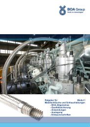
Expansion Joints Guide Module 1 - BOA General ... - BOA Group
Expansion Joints Guide Module 1 - BOA General ... - BOA Group
Expansion Joints Guide Module 1 - BOA General ... - BOA Group

You also want an ePaper? Increase the reach of your titles
YUMPU automatically turns print PDFs into web optimized ePapers that Google loves.
<strong>Expansion</strong> <strong>Joints</strong> <strong>Guide</strong> <strong>Module</strong> 1- <strong>BOA</strong> <strong>General</strong> Information- <strong>Expansion</strong> <strong>Joints</strong> <strong>General</strong>- Quality Assurance- Application Fields- Annex/ Standards
<strong>BOA</strong><strong>Expansion</strong> <strong>Joints</strong> <strong>Guide</strong><strong>Expansion</strong> <strong>Joints</strong> <strong>Guide</strong>Index <strong>Module</strong> 11 <strong>BOA</strong> GENERAL INFORMATION 32 EXPANSION JOINTS GENERAL 42.1 Main elements and their functions52.2 The bellows and its function52.2.1 The one to five-layer bellows, produced by hydraulic complete forming (Hydraulic Formed Bellows HFB)62.2.2 The several to multi-ply bellows (2 to 16 layers), produced by elastomer single convolution shaping (Elastomer7Formed Bellows EFB)2.2.3 Calculating the multi-ply bellows82.2.4 Criteria for problem-oriented choice of bellows82.3 Unrestrained expansion joints92.4 Restrained expansion joints92.5 The inner sleeve (protection tube)92.6 Types of connection102.6.1 <strong>Expansion</strong> joint for welding in102.6.2 <strong>Expansion</strong> joint with welded flange connection102.6.3 <strong>Expansion</strong> joint with loose (movable) flange connection102.7 Determination of movement parameters112.8 Criteria for choosing the type of compensation122.8.1 Natural expansion compensation122.8.2 <strong>Expansion</strong> compensation with unrestrained expansion joints122.8.3 <strong>Expansion</strong> compensation with restrained expansion joints132.8.3.1 <strong>Expansion</strong> compensation with angular expansion joints132.8.3.2 <strong>Expansion</strong> compensation with lateral expansion joints132.8.3.3 <strong>Expansion</strong> compensation with pressure balanced expansion joints132.9 Anchor points, pipe alignment guides, suspended holding devices132.10 Nominal conditions152.11 Materials172.12 Approach in practice182.12.1 Data requirements / Check list183 QUALITY ASSURANCE 203.1 Approvals / Certificates203.2 Tests / Laboratory214 APPLICATION FIELDS 224.1 Diesel and gas engines224.2 Aerospace224.3 Power distribution234.4 HVAC234.5 Hydraulic engineering234.6 Plant construction, general piping construction244.7 Pumps and compressors244.8 Gas turbines245 ANNEX/ STANDARDS 255.1 Symbols used in pipe construction255.2 Table on guide analyses and characteristic strength values265.3 International standards / Comparison table285.4 Conversion tables295.4.1 Pressure295.4.2 Other conversion tables305.5 Corrosion 325.5.1 Technical information325.5.2 Corrosion resistance table33<strong>BOA</strong> Holding GmbHLorenzstrasse 2-6D-76297 StutenseePhone +49 7244 990Fax +49 7244 99227sales@de.boagroup.comwww.boagroup.com13-05/gli2
<strong>BOA</strong><strong>Expansion</strong> <strong>Joints</strong> <strong>Guide</strong>1 <strong>BOA</strong> <strong>General</strong> Information<strong>BOA</strong> <strong>Group</strong> – globally active<strong>BOA</strong> <strong>Group</strong> is one of the world's leading manufacturers for flexible mechanical elements for theautomotive industry and for a wide range of industrial applications: expansion joints made ofsteel, rubber and PTFE, metal bellows and metal hoses. The headquarter is based in Stutenseenear Karlsruhe/ Germany.Until August 2006 <strong>BOA</strong> operated under IWKA Balg- und KompensatorenTechnologie GmbH.About 20 subsidiaries and holding companies in twelve countries form now the <strong>BOA</strong> <strong>Group</strong>.Additionally, the organization runs sales and service offices in the most important industrialcountries.<strong>BOA</strong> <strong>Group</strong> develops, produces and distributes worldwide stainless steel components for motormanagement, exhaust systems and side components for vehicles. In the industrial division,<strong>BOA</strong> delivers pressure-tight and flexible elements for applications in energy technics and technicalconstruction: railway, shipyards, aerospace industry, vacuum technique, measurementand control as well as armatures.<strong>BOA</strong> solutions include both standardized products and customized, individual elements developedtogether with the customer for the most various and individual application fields.<strong>BOA</strong> Balg- und Kompensatoren-Technologie GmbH, Stutensee,Germany<strong>BOA</strong> BKT GmbH, based in Stutensee near Karlsruhe/ Germany, is the headquarters of theglobally active <strong>BOA</strong> <strong>Group</strong>. Here, expansion joints, bellows and metal hoses are produced forthe automotive industry as well as for applications in energy technics and technical construction:railway, shipyards, aerospace industry, petrochemical industry, vacuum technique, measurementand control and many more.<strong>Expansion</strong> joints produced by <strong>BOA</strong> BKT are made with Hydraulic Formed Bellows(HFB). The heart of the expansion joint, the bellows, consists of 1 to 5 layers. It is characterizedby robustness.<strong>BOA</strong> AG, Rothenburg, Switzerland<strong>BOA</strong> AG, based in Rothenburg near Lucerne, was founded in 1906. About 200 employees areresponsible for development, production, marketing and sales of high-quality expansion joints,metal bellows and metal hoses. Main activity sectors are aerospace equipment, power plant installations,gas and diesel engines, vacuum applications or gas pipeline systems.<strong>BOA</strong> is certified according to EN 9100, ISO 9001 and 14001, DIN EN 15085-2 and ISO 3834-2.<strong>Expansion</strong> joints produced by <strong>BOA</strong> AG are made with Elastomer Formed Bellows (EFB).The heart of the expansion joint, the bellows, consists of 2 to16 layers. It may absorb largerexpansions and is very flexible.Product range of <strong>BOA</strong> <strong>Group</strong><strong>Expansion</strong> jointsFor pipe systems in chemical and refinery plants, power plant engineering, district heating anddiesel engine manufacturing.Metal BellowsAs elastic connections and seals in instruments, valves and fittings, plant and chemical engineering,electrical engineering, vacuum technique, solar and heating installations, automotiveengineering, measurement and control equipment.Metal HosesMade of stainless steel, used wherever flexibility and highest reliability are required, e.g. gasdistribution systems in domestic, commercial and industrial buildings, solar and heating engineering,but also in the automotive industry, aerospace and in many other industrial applications.Plastic ComponentsHose lines, high pressure hoses, expansion joints and steel piping, whose parts in direct contactwith the flow are covered by plastics, offer big advantages, as plastics are mostly resistantagainst corrosion. Depending on the application, these covers are made of PTFE, PFA orEPDM (rubber).3
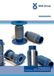
<strong>BOA</strong><strong>Expansion</strong> <strong>Joints</strong> <strong>Guide</strong>2 <strong>Expansion</strong> <strong>Joints</strong> <strong>General</strong>The main function of expansion joints in their various constructions is to compensate for movements in pipe systems, machines and equipment.The movements to be compensated are always relative motions between two parts of a system, caused by temperature differences, misalignmentduring installation, inertial forces or foundation lowering. <strong>Expansion</strong> joints are universally applicable in almost every industrial sector.Particularly in pipeline engineering, they allow space-saving pipe routing for transporting a variety of media such as hot water, steam, fuel, heattransfer fluids, hot gases and various types of chemical products. Another application field is the apparatus and motor engineering, where theexpansion joints decouple vibrations and structure-born noise from diesel engines, turbines, pumps and compressors, preventing their transferto the continuing lines. At the same time, expansion joints allow nearly force-and torque-free connection of pipes to sensitive fittings, appliancesand equipment (e.g. to turbine nozzles). Moreover, expansion joints serve as assembly aids for pipe elements such as valves, where they areused as dismantling pieces or couplings.Overview <strong>Expansion</strong> <strong>Joints</strong> according to EN 14917TypeAxial<strong>Expansion</strong>JointNon-pressurebalancedinternallypressurizedNon-pressureexternallypressurizedDesignPressurethrustrestraintAxialMovementAngularSingle Multiplane planeSingleplaneLateralMultiplaneNo X (X) (X) (X) (X)No X (X) (X) (X) (X)In-linepressurebalancedYesXAngular<strong>Expansion</strong>JointHinge Yes XGimbal Yes X XTwo tie-barssphericalYes X X XLateral<strong>Expansion</strong>JointTwo tie-barspinned(plane)Three or moretie-barsYesYes X XXDouble hinge Yes X XDouble gimbal Yes X X X XUniversal<strong>Expansion</strong>JointUnrestrainedOne or twobellowsPressurebalancedNo X X X X XYesXXWithtwo tiebarsonlyXXNOTE 1 X – ApplicableNOTE 2 (X) – Limited useThe table shows an overview of expansion joints types, laid out according to their main function and construction characteristics with the possiblemovement compensation. Particularly to be remarked: all unrestrained types, while under pressurisation, perform a pressure reaction force(= product of pressure x cross-section of expansion joint) on the piping. Therefore these pipings need to be particularly fixed and guided.4
2.1 Main elements and their functionsAs the above displayed overview table shows, there are expansion joints designs, depending on a variety of different compensation tasks.Usually, expansion joints have the following components:Bellows:They are the flexible element oft the expansion joint and are designed, depending on the requirements, with different numbers of corrugationsand layers.<strong>Guide</strong> sleeves:They protect the bellows against the flowing medium and reduce the flow resistanceProtective tubes, guiding tubes:They protect the bellows against mechanical damage and, depending on the design, prevent the expansion joint from lateral deflection (buckling).Fittings:They make the connection to the continuing piping. Depending on the design, the following fittings are available: weld ends, ends to be soldered,flanges, threaded nipples.Restraint (only for lateral-, hinge or pressure balanced types):The restraint transmits the pressure reaction force over the single or, depending on the design, multi bellows. Simultaneously the restraintdetermines the kinematic flexibility of the expansion joint by incorporating different types of hinge bearings, such as ball joints, single axis bearingswith bolts, U-joint or gimbal bearings.By combining the above shown main elements, depending on the compensation task, the various types and designs can be generated, whichare displayed in the following standard programs of the <strong>BOA</strong> <strong>Group</strong>, by types, sizes, pressure ratings and expansion compensation.2.2 The bellows and its functionaxial movement angular movement lateral movementThe core element of every expansion joint is the metal bellows (*), which by its corrugation geometry and thin-walled design has a large flexibilityin axial, lateral or angular direction, as well as a high pressure resistance. As a condition to be used as an expansion element, the bellowsmust meet the following basic requirements:(*) Exceptions are the rubber expansion joints with their particular operating conditions5
The bellows mustwithstand the operating and test conditions (pressure, temperature) of the pipe system,be corrosion resistant against internal and external influences,be able to compensate for flexible expansions or possible oscillations, and achieve a specified life time or number of load cycles andhave sufficient stability against bucklingUsing corrugations in form of a lyre (see fig.1) is a good compromise between the contradictory requirements for high flexibility combined withhigh compressive resistance. They are the preferred corrugation shape for standard bellows. By changing the radii, the profile height, the numberof layers and the wall thickness, their geometry may be adapted to the requirements on pressure and expansion capability.fig. 1 fig. 2 fig. 3In contrast, a toroidal corrugation profile (see fig. 2), has a high compressive resistance with reduced flexibility, whereas a membrane-shapedcorrugation profile (fig. 3) has the highest flexibility, but a low compressive resistance.Within <strong>BOA</strong> <strong>Group</strong>, all profile shapes are produced and may be supplied on request.2.2.1 The one to five-layer bellows, produced by hydraulic complete forming (Hydraulic Formed Bellows HFB)Traditionally, <strong>BOA</strong> BKT produces one-layer bellows, but at higher pressure and movement requirements up to five layers can be manufacturedby nesting in sleeves one into the other.fig. 4The bellows cylinders are made of strip material following the procedure steps shown in fig. 5: cutting, rounding and longitudinal welding..cutting, rounding longitudinal schweissen weldingone layer22 –– to 55 lagig 5 lagig layersje depending nach Lagen-ozahl required ineinander number ofthegesteckte Hülsenlayers, sleeves arenested one into theotherfig. 56
The bellows is manufactured as shown in fig. 6, out of one or several thin-walled cylinders, nested one into the other, using the hydraulic completeforming procedure.pinternalpressureone layerBellows manufacture2 to 5 layers with relief borefig. 6To ensure that the inner bellows layer is welded tightly to the weld end, the outer support layers of bellows consisting of more than one layerare provided with a relief bore. In this way it is possible to check the tightness of the inner layer by means of a leak test.2.2.2 The several to multi-ply bellows (2 to 16 layers), produced by elastomer single convolution shaping (Elastomer Formed BellowsEFB)<strong>BOA</strong> AG as the inventor of the several or multi-ply bellows, continues to evolve this procedure, manufacturing bellows made of austenitic andother high-quality materials. The number of layers of the standard products can vary from a minimum of 2 to a maximum of 16 layers.Using thin strip material, two leak tight inner tubes and one outside tube are manufacturedby longitudinal welding. Between them, depending on pressure and temperature, startingfrom a certain number of layers, strip material is spirally wound up and put together to acompact cylindrical pack (see picture at left). The single cylinders may consist of differentmaterials, e.g. to obtain cost-effective solutions for increased corrosion resistance.By pressing out annular corrugations through elastomer cold forming, the multi-ply bellow ismanufactured with the particularly favourable technical properties:• high flexibility• short construction length• small displacement forces• large movement capacities• small corrugation height• vibration absorbingThese virtues bring cost-effective solutions, such as small number of expansion joints, smalldimensions of shaft structures or low cost solutions for anchor points. The multi-ply bellowshas also a positive effect on the safety of the expansion joint.If ever the layer in contact with the medium should start leaking, e.g. by overstress or fatigue,the medium will try to find its way slowly through the labyrinth of the multi-layers. Oncearrived out-side, it will automatically display the leak at the control bore.This principle has the following safety benefits:Control bore• early detection of leaking• possibility of permanent leaking control while using dangerous media (by means ofthe relief bore)• despite weak leakage, pressure resistance and functionality of the expansion jointare maintained for a certain time (weeks, months)• no need of immediate replacement• spontaneous bursting is impossible.Multi-ply bellows also show their advantages used in vibration absorbers. Thanks to the compact layer structure, friction effects arise inside thebellows pack, and as the bellows is moving, the force-deflexion-graph develops hysteresis.• Thus, the principle of the multi-layer bellows is an excellent solid-borne sound absorber. Similar results are reached as with rubberelements, plus the advantage of higher resistance against temperature, pressure and ageing..7
Properties of single-ply compared to multi-ply expansion joints• high plane and column stability with the same wall thickness• high corrosion resistance due to thicker wall thickness• reduced vulnerability to external damage• own repair welding may be possible at leakage2.2.3 Calculating the multi-ply bellowsThe positive effect of the very flexible multi-ply bellows compared with the single-ply expansionjoints is easy to demonstrate with a simple bending bar. It is evident, that at the same bendingrate and the same dimensions, with half of the bar’s thickness a, the bending stress F2 is alsohalved, and the displacement force of the two-layer bending bar is only one quarter of the originalvalue.Usually, the bellows are exposed to extreme static or dynamic forces generated by internalpressure, temperature, vibrations etc. Compared to a fix pipe system, the calculation of the effectsof the varying forces on a multi-ply bellow becomes very complex.To meet the high safety requirements, engineering must be supported by a reliable and testedcalculation method. <strong>BOA</strong> makes use of the results and knowledge of the group of Americanexpansion joints manufacturers (EJMA), published since 1958. This calculation method hasbeen proven for multi-ply expansion joints and is recognized by all international certification authorities.2.2.4 Criteria for problem-oriented choice of bellowsThe following standard programs of <strong>BOA</strong> enable the user to choose the type of bellows and expansion joint particularly suitable for the targetedapplication. For better understanding, the different options available in bellows technology (HFB / EFB) will be explained with an example.Let’s first consider a single-layer bellows with 4 convolutions and a wall thickness of s = 1mm.With a profile height of H = 28mm, the bellows is suitable for an operating pressure of p adm = 10 bar, and has an expansion capability of Δ ax = ±12mm at an axial spring rate of c ax .If we want to realize the same performance for pressure resistance and expansion capability with a multi-layer bellows, we already need 4layers (each one with a wall thickness of s = 0.5 mm) to achieve the same pressure resistance. However, the individual layer thickness beingonly half, the expansion capability per convolution doubles, so that for a movement capacity of Δ ax = ±12mm only 2 convolutions would berequired, or keeping the same number of convolutions (4), we reach now the double expansion capability Δ ax = ±24mm at about half the springrate (0.5 c ax ).In the next step we further reduce the layers’ wall thickness to 0.3 mm. Again, to achieve the same pressure resistance, 9 bellow layers arenow required, which, at the same number of convolutions (4), triple the expansion capability to Δ ax = ±36mm and lower the spring rate to a third.The dependencies are summarized in the table below:admissible working pressure p adm = 10 bar, profile height H=28 mmlayer thickness s (mm) number of layers n number of convolutionsWexpansion capability Δ ax(mm)spring rate1 1 4 ± 12 c ax0,5 4 4 ± 24 0,5 c ax0,5 4 2 ± 12 c ax0,3 9 4 ± 36 0,33 c ax8
If the primary compensation task is to absorb a specific thermal expansion, regardless of the length and the displacement forces of theexpansion joint, as in the case e.g. of axially compensated district heating pipelines, a bellows of one or few layers will sufficiently solve thecompensation task.If space conditions for installing the expansion joint are restricted, a multi-ply bellows will significantly reduce the overall length.However, if the connection forces or moments on a sensitive turbine or equipment nozzle are the main argument, then these can be reducedto one third by choosing a multi-layer bellows, compared to the single-ply solution with equal length.If the compensation task is to isolate or damp oscillations of small amplitude, the use of few or multi-ply bellows has a dampening effecton the upcoming forced vibration, due to the layers friction.2.3 Unrestrained expansion joints<strong>Expansion</strong> joints without tie rods (axial and universal), while under pressurization, act a reactionforce FP (= product of overpressure p x cross section area [AB]) upon the pipe system andthe anchor points.The bellow’s cross-section [AB] may be taken from the dimension tables of the expansion jointstypes. At high pressure rates and large nominal sizes, the reaction force increases considerably,e.g. at a pressure of 40 bar and 400 mm nominal size, the reaction force is approx. 600 kN.Therefore the anchor points have to be massive..2.4 Restrained expansion jointsThe reaction force, explained before, is taken up by a tie bar system, i.e. articulation elementsor tie rods. Depending on the pipe routing and the occurring movements, the appropriate typeof restrained expansion joint is chosen. Despite the restraining element, the overall length ofthe expansion joint remains short, thus being also advantageous for system solutions.If high pressures or pressure impacts occur, and to avoid massive and expensive anchor pointconstructions, the experienced engineer will choose restrained expansion joints.Along with taking up the reaction force and its correct transmitting into the connecting parts, thetie rods support the articulation elements, thus ensuring the motional function. Besides, very oftenthere are additional loads and moments to transmit. It is evident, that the dimensioning ofthe restraining elements has to be supported by a reliable and tested calculation method. <strong>BOA</strong>engineers are using FEM, calculating with the non linear limit analysis. Their results mainlymeet the values received during many practical experiments and burst pressure tests.2.5 The inner sleeve (protection tube)Inner sleeves protect the bellows and prevent it from being activated into vibrations, caused bythe medium’s high speed. The installation of an inner sleeve is recommended,• if abrasive media are used• if large temperature variations are expected• to prevent the deposition of solid parts in the corrugations• if the flow rate is higher than approx. 8 m/sec for gaseous media• if the flow rate is higher than approx. 3 m/sec for liquidsFor further instruction see "Installation and Operating Instructions"9
2.6 Types of connectionDepending on the application, replaceability, safety or pressure rate, usually three methods for connecting the expansion joint to the pipe systemor to the unit are distinguished.<strong>Expansion</strong> joint for welding in<strong>Expansion</strong> joint with weldedflange connection<strong>Expansion</strong> joint with loose (movable)flange connection2.6.1 <strong>Expansion</strong> joint for welding inThe advantages of this connection type are:1. The outside dimensions of the connection are compact to the continuing piping2. The leak tight weld seams (which may be examined by non destructive test methods) forthe application under elevated pressure conditions or with dangerous fluids.Welding the multi-ply bellows made of austenitic steel to the ferritic weld end (or flange) is aprocess which requires particular measures, skills and experience. It is one of the decisivepoints for the quality of the expansion joint. With the necessary checks, <strong>BOA</strong> guarantees thecapture of bellows’ layers into the welding, a massive and continuous weld structure and a minimalheating zone. With our tested and optimized welding process, weld flaws, heat cracks, inclusions,pores and blowholes are excluded..2.6.2 <strong>Expansion</strong> joint with welded flange connectionThe advantages of this connection are rapid replaceability and the expansion joint’s short overalllength. Regarding the connection weld between flange and multi-ply bellows, the same highstandards apply as for weld ends.2.6.3 <strong>Expansion</strong> joint with loose (movable) flange connectionThe advantages of this connection are, as with welded flanges, easy replaceability, fast assemblyand the short overall length.Furthermore, the austenitic bellows, forming a collar on both sides, allow flange rotating. Incase of non-aligned hole patterns and aggressive media inside, the bellows’ collar protects theflanges, so that no specific flange material is required. However, this type of flange connectionis not available for all pressure levels.10
2.7 Determination of movement parameters<strong>Expansion</strong> joints compensate for various movements, caused by different sources, such asinstallation misalignmentvibrationsinstallation gapextension caused by pressure forcesoil subsidenceelongationElongation usually causes the highest movement value.Installation misalignmentMisalignment occurs very often during pipe installation. These imprecisions may be compensated by expansion joints, if they were alreadyconsidered in the system design. In this case, the expansion joint’s life time is hardly affected, because it is a one-time movement. On the otherhand a complete or partial blocking of the corrugations may be caused, if short axial expansion joints are installed. The indicated movementcompensation would be hindered, leading thus to early failure of the expansion joint.VibrationsVibrations of different frequency and amplitude are caused by rotating or shifting masses in installations such as pumps, piston machines,compressors etc. These vibrations not only make annoying noise, but stimulate connecting pipes to the extent of fatigue causing early failure.Thus the operating stability and economic efficiency of the installation is at risk.Installation gapDuring the installation of pipe systems, particularly when subsequent removal and replacement of individual components is necessary, an axialinstallation gap is essential for easy replacement of the modular elements. The so-called disassembly joint may bear a larger movement up toblock position of the convolutions, as the frequency of replacement is usually low.Extension caused by pressure forceExtensions occur in vessels and piping put under pressure force. Their values only have to be considered at larger diameters.Soil subsidence<strong>Expansion</strong> joints may take up larger subsidence movements, because it is a singular occurrence (no stress cycles). The expansion joint mayeven endure an excessive deformation of the bellows without leakage.ElongationThermal expansion of different metalsChanges in the length of a piping are mainly caused bytemperature variations. These changes in length have aninsignificant effect in radial direction due to the pipe geometryand can be neglected, since pipe diameter is muchsmaller than pipe length. However, lengthwise variations ofvolume deserve close attention, since it can become quitesignificant when temperature and pipe length increase.Each material has its own expansion coefficient which forthe different types of iron and steel varies in rather narrowrange. The differences become more significant for steelalloys such as heat resistant steel, stainless steel or highheat resistant metals and their alloys such as nickel, Monel,titanium, Inconel, Nimonic etc. Copper and aluminiumand their alloys have even bigger expansion coefficients.Using the specific <strong>BOA</strong> slide rule, the elongation may bedetermined quickly and almost exactly.For thermoplastic lines the length elongation is more thantwice as large as for steel pipes.11
2.8 Criteria for choosing the type of compensationBasically there are three types of compensation to consider:• elastic bending of existent pipe legs (natural expansion compensation)• expansion compensation with unrestrained expansion joints• expansion compensation with restrained expansion jointsWhich of the three types is to be chosen also depends on the following criteria:• extension and type of the movement to compensate for• pipe design• installation and assembly conditions• dimensioning of anchor points and connections with regard to forces and moments• total cost of the compensation (compared to costs of the anchor points)MovementsAxial and lateral expansion jointsWith axial and lateral expansion joints the occurring expansion corresponds to the real compensation movement.Angular and gimbal expansion jointsWith angular and gimbal expansion joints the occurring expansion must be converted into an angular movement. This conversion is describedin detail in <strong>Module</strong> 3a, angular expansion joints.2.8.1 Natural expansion compensationIf local conditions allow the alignment of the pipe system between two anchor points in such a way that heat expansions of the pipe are compensatedby the elastic reaction of the pipe elbows and legs (bending, twisting), these effects have to be exploited. However, installing extrapipe legs is not an economic solution. Natural compensation is only useful, if the pipes are able to compensate, additional to the stressescaused by internal pressure, the stresses resulting from the movement cycles, and that without early ageing.Using your own software and tables, we can advise customers whether a natural expansion compensation is possible or if expansion joints areto be provided.<strong>Expansion</strong> compensation of right-angled pipe legs2.8.2 <strong>Expansion</strong> compensation with unrestrained expansion jointsThe reaction force and spring rate of unrestrained expansion joints shall be taken up by the anchor points at both ends of the pipe section. In alonger pipe system, where several expansion joints are installed in series, pipe sections should be created by means of intermediate anchorpoints. An axial expansion joint shall be placed in each section. The anchor points at both ends of the straight pipe section shall withstand thefull reaction force. The intermediate anchor points have primarily to take up frictional and displacement forces.Axial expansion joints compensate for axial pipe elongations. Therefore, the piping shall be coaxial with the expansion joint. Small lateralmovements of a few millimetres are acceptable, however, they reduce the life expectancy of the axial expansion joint, if the allowable axialmovement is simultaneously fully used.Advantages:• simple way of compensation• no change in flow direction• minimal space requirementsDisadvantages:• strong anchor points and good axial pipe guiding required• several axial expansion joints are needed for large elongations• many anchor points and pipe guides are needed for long pipe sectionsBetween two anchor points only one unrestrainedexpansion joint shall be installed.12
2.8.3 <strong>Expansion</strong> compensation with restrained expansion jointsCompared with unrestrained expansion joints, those equipped with tie rods only need light anchor points (sufficiently firm supports). The reactionforce coming from the bellows is taken up by the restraints and acts as an anchor point load. Only the spring rate of the bellows and thefriction forces of the restraint act effectively on the anchor points. The anchor points shall be calculated to resist to the friction forces at the pipeguide supports and to the displacement forces of the expansion joints. Restrained expansion joints may be of the angular and lateral type. Asanother possibility, the use of pressure balanced expansion joints is given.2.8.3.1 <strong>Expansion</strong> compensation with angular expansion jointsAngular (or hinged) expansion joints are used for large pipe elongations. A system of expansion joints is built of standard elements. This requirestwo or three expansion joints. The installation of angular expansion joints always requires a change in the direction of the piping. Therefore,they are preferably placed where a 90° bend has originally been foreseen. The elongation absorption of hinged expansion joint systems ispractically unlimited. It is determined by the piping size, allowable movement‘s angle of the hinged expansion joints and the length of the pipesection between two angular expansion joints.Advantages:• almost unlimited expansion compensation• small load on anchor points• modular concept application• use of normal guidesDisadvantages:• change in pipe direction is always required• more space required compared to axial expansion joints• two or three expansion joints required for a system2.8.3.2 <strong>Expansion</strong> compensation with lateral expansion jointsLateral (or swing) expansion joints, equipped with ball joints, can move in all directions within one circularplane. They are used for simultaneous or staggered movements from two directions. At sufficient length,these expansion joints can take up considerable amounts of movements. More frequent is the use of shortlateral expansion joints with ball points for small elongations when the pipe layout is complex, or for stresslessconnections directly before sensitive equipment, such as pumps, compressors and machines.If two ball joint expansion joints are arranged at right angles, such a system takes up elongations in allthree directions (lateral expansion joints possible only with 2 tie rods, observe the installation position ofthe tie rods). The installation of lateral expansion joints always requires a change in direction of the piping.Advantages:• movement compensation in all directions in one plane• expansion compensation in all three directions possible, if a lateral and an angular expansion joint areused (construction detail of lateral expansion joint: only with two tie rods, observe the installation positionof the tie rods)• small load on anchor pointsDisadvantages:• change in pipe direction is necessary• more space required compared with axial expansion jointsProvide a double ball joint for vacuumapplications!2.8.3.3 <strong>Expansion</strong> compensation with pressure balanced expansion jointsThere are many types of special constructions such as pressure balanced axial expansion joints, pressure balanced angular expansion joints, acombination of axial and lateral expansion joints. There are standards covering such systems, but the expansion joints themselves are notstandardized. It is recommended to consult the manufacturer in these cases, because special constructions are sometimes technically efficient,but nevertheless the most expensive solution.Advantages:• small anchor point loads• minimal space required• technically efficient solutionDisadvantages:• custom-built, therefore higher costs2.9 Anchor points, pipe alignment guides, suspended holding devicesRegardless of the type of expansion joint being applied, anchors shall always be provided at each end of a pipe. When axial expansion jointsare used, each bend, right angle turn or considerable pipe direction change must be anchored. Pipelines whose elongation is compensated byseveral expansion joints, must be divided by anchor points into as many parts as expansion joints are necessary. The location of anchors isdetermined on the one hand by the direction of the piping, on the other hand by local conditions. However, their capacity of providing goodanchorage is essential.13
The corrugated bellow of the expansion joint tends to stretch out when subjected to internal pressure, and to contract under inner vacuum. Thispressure or tensile force, the reaction force of the bellows, is transferred to the piping and has to be neutralized by the anchorage of the piping.The strength of the anchor point, and therefore basically its design, is determined by the reaction force. In this case, not the reaction force ofthe operating pressure, but of the test pressure is relevant, because the anchorage must absorb the reaction force of the test run, when thepiping is put under pressure. However, the test pressure should not exceed 1,5 times of the operating pressure. The spring rate of the bellowmust be added to the reaction force, however it usually amounts to only a small percentage of the latter. If a sufficient number of anchor pointscannot be provided, restrained expansion joints such as angular, lateral or pressure balanced axial expansion joints should be used.Anchor points within straight pipe sections may be of lighter structure, because they only have to take up the spring rate of the bellows and thefriction forces of the guides. Whereas they must not take up the reaction force, acting only on points of change in pipeline direction, on its crosssection variation or on its shutoff devices (valves, slides). If the pipe diameter is changed, the difference in reaction force between the largerand the smaller pipe cross section must be added to, or subtracted from the other forces. The design of an anchor point can be quite simple.Below some possible and often used anchor designs are displayed. Local conditions determine the choice of the most suitable type.Examples of anchor points:Examples of pipe guides:Examples of pipe guides and anchor points:14
2.10 Nominal conditionsThe expansion joints listed in the technical data sheets are classified by type, nominal size (DN), nominal pressure (PN) and movement capacity.Several factors must be considered for proper selection of an expansion joint.Nominal size DNThe nominal size of the expansion joint to be selected is based on the existing flange or pipe dimensions.The outside diameter of the expansion joint‘s weld ends corresponds to the ISO range. The exact connection dimensions, in particular the wallthickness, are listed in the technical data sheets.The connection dimensions of expansion joints with flange connection are listed according to EN 1092.Nominal pressure PNFor standard expansion joints, the nominal pressure (PN) is a ratio that indicates the admissible working pressure PS at nominal temperature(20 °C).If the expansion joint is used at a temperature above the nominal temperature, its pressure load capacity is reduced by the derating factor K P .For convenience, the derating factors K P , depending on the temperature, are directly given in the technical data sheets.The admissible working pressure PS of an expansion joint at working temperature TS is calculated as follows:PS (TS) = PN * K P (TS) [bar]If an expansion joint must be chosen for working pressure PS and working temperature TS, then first the fictive pressure value P e must bedetermined (converted to nominal temperature), which must be less than or equal to the required nominal pressure PN.P e = PS / K P (TS) ≤ PN [bar]Nominal movement capacityThe nominal movement capacity given in the technical data sheets indicate the displacement, the expansion joint can take up at nominal temperatureout of its neutral position. For an axial expansion joint, e.g., ± ax indicates that the expansion joint is able to take up 1000 full loadcycles at nominal pressure and a total expansion of 2 · ax within the neutral position, compressed or stretched by ax . It is irrelevant whetherthe load cycle starts in the compressed, neutral or stretched position.To make usable the total expansion of 2 · ax for compensation, it is necessary to pre-restrain the expansion joint by 50 % of the total displacement,i.e. by ax . The same applies to the lateral or angular movement compensation (± lat or ± α).Particularly easy to fit are the axial expansion joints of our standard program, which are able to take up their total expansion on compressionwithout needing on-site pre-restraining.For these expansion joints, the nominal axial expansion compensation ax corresponds to the total expansion on compression.If an expansion joint is used at a temperature above the nominal temperature for expansion compensation, the movement capacity is reducedby the derating factor K .The derating factors K (TS) are indicated on the technical data sheets as a function of temperature.The admissible movement capacity ± adm (TS) or ± α adm (TS) of an expansion joint at working temperature TS is calculated as follows:± adm (TS) = ± * K (TS)If a certain working condition needs a movement capacity of ±TS at working temperature TS, then the necessary nominal movement capacityof the expansion joint to be chosen is to be determined as follows:± ≥ ±TS / K (TS)15
Inherent resistance of the Bellows ± 30% (spring rate)The inherent resistance (spring rate) of the bellows is a force (moment), the bellows withstand a movement.The bellows‘ specific spring rate per ± 1 mm (1°) is indicated in the technical data sheets as spring rate. For production reasons, a tolerance of± 30% is applicable for the values listed.Life timeThe life time (life expectancy) of an expansion joints is defined by the minimum number of full-load cycles that can be taken up until a leakcaused by fatigue will appear. The maximum permissible expansion capacity is indicated on the expansion joint. It refers to 1000 full-loadcycles (expansion joints conforming to EC standards: 500 full load cycles with safety factor 2).The nominal expansion capacity given in the technical data sheets refer to a minimum life time of 1000 full-load cycles at nominal conditions.A load cycle means the movement cycle, the bellows is running through between the two extreme positions during the application and removalof the total expansion capacity.For example: a pipeline is brought from ambient temperature to full operating temperature, and then cooled down again. For an expansion joint,built into the pipeline, this procedure means a full load cycle.In normal cases, a design for 1000 full-load cycles is absolutely sufficient.If higher load cycles are required, such as e.g. for industrial plants with several operating intervals per day, the expansion capacity must bereduced by the load cycle factor K L (see table).Load cycle factor K LLoad cyclesN adm1'0002'0003'0005'00010'00030'00050'000100'000200'0001'000'00025'000'000Load cycle factorK L1.000.820.730.630.510.370.320.260.220.140.05K L = (1000 /N adm ) 0,29Life-reducing additional effects such as corrosion, impact stress caused by explosions, water hammer or thermal shocks, resonances due toflow-induced or mechanical influences can not be calculated and are therefore inadmissible.If during operation, in addition to the static inner pressure, dynamic pressure variations occur, they will reduce life time. If the pressure variationsare on a low level within the nominal pressure range, the influence on the life time is small and in most cases negligible. If in individualcases there is uncertainty regarding the rating of the impact, please inquire.Load spectrumIf an expansion joint shall be designed for different load cases, the degree of fatigue (D i ) of each load spectrum must be linearly accumulatedD = D i = (n i /N i ) ≤ 1where n i means the necessary and N i the allowable number of cycles of each load case.Example:Load case 1 with n 1 = 500 load cycles at 100 % nominal expansion capacity with N 1adm = 1000.Load case 2 with n 2 = 10 000 load cycles at 30 % nominal expansion capacity (K L = 0.3) withN 2adm = 1000 / (K L 3,45 ) = 63670resulting in an overall fatigue degree ofD = n 1 / N 1adm + n 2 / N 2adm = 0,66
2.11 MaterialsThe materials used for metal bellows, whether single-ply or multi-ply must meet various conditions.These are:WeldabilityIt must be fundamentally ensured. The longitudinal weld seams must meet the same conditions as the base material.DuctilityIt is a prerequisite for the production of cold-formed bellows, however sufficient residual elongation at rupture must be ensured.Mechanical strength propertiesHigh mechanical strength is a prerequisite for pressure resistance. Simultaneously the elastic range is extended.Technological propertiesThese include the strength properties under alternating flexural stress for expansion joints. They are not only determined by the alloyingcomponents, but also by surface conditions, by the grain size and by the metallurgic microstructure.Corrosion resistanceThere is no corrosion allowance for expansion joint bellows. It would have a negative influence on the bellows’ expansion properties.Therefore, only materials being corrosion resistant against the concerned medium are possible.Temperature propertiesThis means the materials’ resistance to heat or cold and their long-term behavior. Almost all of austenitic chrome-nickel steels are toughdown to -200°C and usually meet all requirements up to 550°C.For applications working at temperatures above approx. 550°C, special heat resistant materials are used.Mainly stainless steels fulfil the above mentioned criteria. The general term for these materials is "stainless steel". They generally contain morethan 12% chromium (Cr) and are resistant to oxidizing agents attack.Higher chromium contents and other alloying elements such as nickel (Ni), molybdenum (Mo) and nitrogen (N) improve the corrosion resistance.Also the mechanical and technological properties are strongly influenced by these or other additives. Containing at least 8% nickel, the "stainlesssteel" becomes austenitic. These steels are therefore often referred to as, e.g., 18/8, 18/10, or as austenitic chrome-nickel steels.With the formation of a passive layer and the presence of oxygen, "stainless steel" gets its anti-corrosive property.Standard materials for bellows areMaterial n° Short formDIN 17006AISI(USA)1.4541 X6 Cr Ni Ti 18 10 3211.4571 X6 Cr Ni Mo Ti 17 12 2 316 TiThese are austenitic, titanium-stabilized steels with a wide range of application areas.For more aggressive corrosion conditions higher alloyed steels or nickel-based materials shall be used.Pitting resistance equivalent number diagram (PREN)Pitting corrosion potential mV HpH value 7.5Temperature 80°CThe diagram allows estimating the increasing corrosion resistancein aqueous media. The pitting corrosion potential in thiscase represents a measure for the resistance of the materialagainst pitting as a function of the alloy components’ PREN, withthe elements chromium, molybdenum and nitrogen having a significanteffect (see pitting factors).The material 1.4439, for example, due to its content of molybdenumand nitrogen (4-5% Mo, 0.1-0.2% N) has an about twiceas high PREN relative to the material 1.4541, and is thereforemuch more resistant to pitting..PREN %Cr= factor 1 %Mo= factor 3.3 %N= factor 30Pitting potential of austenitic steel as a function of PREN17
2.12 Approach in practiceFor a given routing, see the example to the right, initially anchor points must be setwhere a movement of the line is undesirable, namely at the branch points. In thenext step those line segments are to be considered, where the natural legs are ableto absorb parts of the pipeline expansion. These line segments must be limited byanchor points. For the other line parts, expansion joints must be provided to take upexpansion.Two questions are crucial for the decision, whether axial or hinged expansion joints are to be chosen:The line’s routing and the possibility of taking up axial forces.If it is a pipe system with short, straight sections and stretching movements to about 80 mm, i.e. a system with many changes of direction andjunctions, an axial expansion joint is recommended. In long straight lines with stretching movements higher than 80 mm, hinged expansionjoints are rather used. If the on-site conditions allow strong anchor points and placing enough guides, then the choice of axial expansionjoints is correct. Otherwise, especially in pipes of large cross-section and at high pressure ratios, the hinged expansion joint is also a goodsolution, where small stretching movements occur. Artificially arranged pipe legs are not economical for space and cost reasons. It is quitepossible to compensate for expansion within a piping system using various methods. To each expansion joint, however, a defined task must beassigned, i.e. the section of line to be compensated by it must be limited by two anchor points.The economically most advantageous solution will be found, taking steps in this order when solving problems of compensation in pipelines.Early collaboration with the manufacturer however will always pay off.2.12.1 Data requirements / Check listPlease ask for our technical advice if planning CE-marked expansion joints. You may prepare the necessary information for the expansion jointdesign with the help of this check list. Please add, if possible, an installation sketch and/or an isometric drawing of the pipe system. Make acopy of the following list or download it from our website www.boagroup.com.<strong>BOA</strong> Check list: <strong>Expansion</strong> jointsCompany:Address:______________________________________________________________________________________________________________________________Inquiry n°: ___________________ Person in charge:____________________________Quantity ___________ units DN ______________ mm<strong>Expansion</strong> joint type:axial lateral universal angularlow pressure vibration absorber otherBellows material:exterior ply: 1.4541 1.4404 1.4571 ___________intermediate ply: 1.4541 1.4404 1.4571 ___________interior ply: 1.4541 1.4404 1.4571 ___________Inner sleeve: yes nomaterial: 1.4541 1.4404 1.4571 ___________Fittings: 1 st side 2 nd sidelose flange:welded flange:weld ends:materials 1 st side: 1.4541 1.4301 1.4571 carbon steel ________materials 2 nd side: 1.4541 1.4301 1.4571 carbon steel ________Movement: axial ±_________ mmlateral± _________ mmangular ± _________ °vibrations± _________ mmCycles : 1000500 (standard products and PED 97/23/EC with CE-marking)_______18
Operating conditions:PED 97/23/ECPipingContainerPiping:Type of fluid:_______________________________________group 1: dangerous gaseous / dangerous liquidgroup 2: innocuous gaseous / innocuous liquidContainer: required customer’s indications:container, category: ___________________________________________________fluid type:___________________________________________________fluid group:___________________________________________________Inspection authority: ___________________________________________________Max. operating pressure PS:Min. operating pressure PS:________bar________bar (if also used in vacuum)Max. operating temperature TS:Min. operating temperature TS:________°C________°C (if also used below 0°C)Tests: standard PED 97/23/ECspecial testInspection certificates:EN 10204-2.2 EN 10204-3.1 EN 10204-3.2Conformity declaration according to Pressure Equipment Directive 97/23/ECConformity certificate issued by the inspection authorityMarking: standard EN 10380 customer’s indicationaccording to PED 97/23/ECPacking: standard special customer’s indicationVarious:exterior protecting tube transportation fixing ______________________Issued by:Place / date:Signature:______________________________________________________________________________________________________Schema / sketch:19
<strong>BOA</strong><strong>Expansion</strong> <strong>Joints</strong> <strong>Guide</strong>3 Quality Assurance3.1 Approvals / Certificates<strong>BOA</strong> expansion joints are designed, calculated, manufactured and tested following lates professional and state of the art standards. Regularinspections by accredited authorities for enterprise certification confirm the efficient and professional continuity of <strong>BOA</strong> process management.Company approvalsEN 9100ISO 9001ISO 14001Euro-QualiflexISO 3834-2DIN EN 15085-2Quality Management for Aerospace applicationsQuality ManagementEnvironment ManagementQuality Management SystemCertification as welding companyWelding of Railway vehicles and componentsPED ConformityPressure Equipment Directive PED 97/23/EC (and SR 819.121)authorized for CE markingSwiss Associationfor Technical InspectionsRegulation 501 and704Germanischer LloydEuro-QualiflexProduct approvalsTo cover the particular market orientations, we are in possession of the necessary product type approvals, issued by accredited certificationauthorities.BureauVeritasDet NorskeVeritasRina NKIP Lloyd's Register20
3.2 Tests / Laboratory<strong>BOA</strong> expansion joints may be subject to various quality tests and inspections. The scope of the testing program follows the requirements andwishes of the customer or the design and production standards, as well as the inspection authority’s conditions.Product quality however is a matter of production standards and not of the subsequent tests. Those tests only confirm the rated required qualitylevel. Therefore our production methods are generally based on a high quality level. Additional tests should be required only where the applicationimperatively demands it. If in a particular case design evidence is requested, the requirements must be clearly specified for a review of thepermissible operating data in our factory.Non-destructive test methods TP - water pressure test LT - leak-tightness test with air or nitrogen under water LT - leak-tightness test with air andfoaming agents at the welds (soap bubble test) Differential pressure test with air RT – X-ray test MP - magnetic particle crack test PT - dye penetration test LT – helium leakage test (
<strong>BOA</strong><strong>Expansion</strong> <strong>Joints</strong> <strong>Guide</strong>4 Application FieldsIn almost every technical-oriented industrial area expansion joints are used to ensure the operating stability of the installations. Using flexible,metallic expansion joints in today’s installation and plant construction is not only technically necessary, but also important to meet the industry’sgeneral demands for:• improved profitability• reduced plant size• easy installation• system compatibility• smooth operating• safety in case of incidents<strong>BOA</strong> expansion joints meet all these requirements. Below some of the application fields are listed, where <strong>BOA</strong> expansion joints mainly areused. Nevertheless, our experienced team will be happy to develop, together with your engineers, new applications in all areas where flexiblepipe elements or connections are needed. Please submit your problem – and we will suggest our solution as we have been doing for more thanhundred years.4.1 Diesel and gas engines<strong>BOA</strong> has been supplying to leading diesel engine manufacturers expansion joints in exhaust lines between outlet valve and turbocharger.Through continuous development of our products in this area, we are now able to design and supply complete exhaust systems. <strong>BOA</strong> exhaustsystems are now in use worldwide and have the following customer benefits:one contact person, and therefore less supplierscompact constructionconsiderable cost savings thanks to quick mounting and 50% less weightoptimal and interactive design thanks to state of the art engineering tools with 3D-CAD and ANSIS-FE calculation program100% system tightness because of less intersectionsefficient benchmarking at <strong>BOA</strong>Exhaust line modular assembly system 12/18/20In addition to the complete exhaust systems, we also construct special expansion joints for diesel and gas engine manufacturers, designedaccording to customer’s requirements:<strong>Expansion</strong> joint with V-clamp flanges <strong>Expansion</strong> joint with special flanges <strong>Expansion</strong> joint with bent tubes4.2 AerospaceAll experiences made over decades and in different areas needing sophisticated flexible elements were successfully implemented into aerospaceapplications by <strong>BOA</strong>. The multi-ply expansion joint in this highly demanding application field has the following advantages:low weight thanks to short construction length, small displacement rates and special welding connections<strong>BOA</strong>’s high level welding competence allows using the most different materials, particularly required in this exigent sectoreffective vibration absorptionThanks to the high quality standards, our own test laboratory and the latest calculationsmodules, <strong>BOA</strong> is today able to approach successfully the solution of your problem. <strong>BOA</strong>is certified according to EN 9100.Vibration decoupling unit for helicopters22
4.3 Power distributionThrough many years of collaboration with the leading manufacturers of high voltage SF6 installations, <strong>BOA</strong> has developed different types andprocedures for this special market. Customers take profit from this long experience as follows:worldwide certification according to GIS/GIL standardscost reduction thanks to the connection of the austenitic bellows with aluminium flangesno subsequent cleaning due to manufacturing according to SF6 cleanness directivesAxial expansion joint with aluminium flangesPressure balanced axial expansion joint for high voltage SF6 installations4.4 HVACThe compensation of dilatations in central heating pipe systems is not only a problem for industrial plants and large public buildings, but also inthe private construction sector. The rather long pipelines generate dilatations that can not quite simply be compensated by deviating the piping.In shorter main pipe lines axial expansion joints are used. In long linear main pipe lines hinged and angular expansion joints are needed. The<strong>BOA</strong> standard expansion joints program meets usually the requirements of the heating and ventilation sector.Axial expansion joint Type WSmall (sanitary) expansion joint Type ZaAngular expansion joint Type AWVibration absorber Type Alpha-C4.5 Hydraulic engineeringIn this sector mostly <strong>BOA</strong> disassembly joints are used. Compared with standard demounting joints, <strong>BOA</strong> units have the following advantages: 50% installation time reduction quick availability of the plant by exploiting the spring rate of the bellows 100% tightness because no rubber elements are used (no ageing) economic execution using parts in contact with the medium made of non-corrosive austenitic material compensation of installation misalignment without tightness problemsThe successful use of <strong>BOA</strong> disassembly joints during many years proves the advantagesmentioned above.Water supply, City of Zurich,SwitzerlandFresh water piping, chemical plant,Germany23
4.6 Plant construction, general piping constructionThere is hardly another application field needing more expansion joints than plant constructionor general piping construction. <strong>BOA</strong> expansion joints are successfully installed e.g. in chemicalplants, thermal power plants, petrochemical plants and district heating power plants.The requirements of plant construction are mostly fulfilled by the <strong>BOA</strong> standard expansionjoints program. As a special service for the pipe system engineer, <strong>BOA</strong> may offer stress analysisdata generated by the "Caesar II" program. This helps optimizing construction costs andtrouble-free operating is ensured.Lateral and angularexpansion joints4.7 Pumps and compressorsOscillations/vibrations caused by pumps, compressors, burners, piping equipment etc. and subsequently transmitted to the pipe system, notonly make annoying noise, they also stress enormously the materials exposed to the vibrations. Therefore in this application field mostly <strong>BOA</strong>vibration absorbers (made of metal or rubber) are used. Our vast standard program of metal and rubber vibration absorbers covers almost allapplication fields of pumps and compressors.Rubber and metal vibration absorbersPump station with vibration absorbers4.8 Gas turbinesFor use in gas turbines, particularly pressure balanced expansion joints are used for not exceeding theallowable stresses in the transition piece between the pipeline and the aggregate. Also restrained (lateral/angular) expansion joints are used between turbine and condenser.Pressure balanced expansion joints24
<strong>BOA</strong><strong>Expansion</strong> <strong>Joints</strong> <strong>Guide</strong>5 Annex/ Standards5.1 Symbols used in pipe constructionAxial expansion jointApparatus (without rotatingparts)Angular expansion jointApparatus (with rotatingparts)Universal expansion jointSocket connectionLateral expansion jointFlange jointGimbal expansion jointScrewed connectionPressure balancedexpansion jointCouplingAnchorNon-insulated pipelineVertical holding device(support)Insulated pipelineSuspended holding device(suspension)Flexible pipeSpring suspensionPipe with flow directionindicatorSpring supportPipe crossing withoutconnectionSlidewayPipe crossing withconnectionSuspended pipe slidewayPipe branch withconnectionRoller guide25
<strong>BOA</strong>5.2 Table on guide analyses and characteristic strength valuesMaterialgroupMaterial n°acc. toDIN EN10027Short form accordingto DIN EN 10027Short form accordingto DIN 17006 (old)* Strength values at room temperatureDocumentationUppertemp.limitApparentyieldingpoint min.*Tensilestrength*Breakingelogngationmin.*Impact valuemin.ReH/RP0.2 Rm A5 A80 AV (KV)- - - - - °C N/mm 2 N/mm 2 % % JUnalloyedsteel1.02541.0427P235T1C22G1St 37.0C 22.3DIN EN 10217DIN EN 10216300350235240350-480410-5402320 31<strong>General</strong>structuralsteel1.00381.00501.0570S235JRG2E295S355J2G3St 37-2St 50-2St 52-3DIN EN 10025 300 235295355340-470470-610490-63021-2616-2017-222727/ -20°CTemperatureresistantunalloyedsteel1.0460 C22G2 C 22.8 VdTÜV-W 350 480 240 410-540 20 31Temperatureresistantsteel1.03051.03451.04251.04811.54151.73351.7380P235G1THP235GHP265GHP295GH16Mo313CrMo4-510CrMo9-10St 35.8H IH II17 Mn415 Mo 313 CrMo 4 410 CrMo 9 10DIN 17175DIN EN 10028T1/T2480480480500530570600235235265295275300310360-480360-480410-530460-580440-590440-590480-630232523222420183427 / 0°C27 / 0°C27 / 0°C313131Stainlessausteniticsteel1.43011.43061.45411.45711.44041.44351.44651.45391.4529X5CrNi18-10X2CrNi19-11X6CrNiTi18-10X6CrNiMoTi17-12-2X2CrNiMo17-12-2X2CrNiMo18-14-3X1CrNiMoN25-25-2X1NiCrMoCu25-20-5X1NiCrMoCuN25-20-7X 5 CrNi 18 10X 2 CrNi 19 11X 6 CrNiTi 18 10X 6 CrNiMoTi 17 12 2X 2 CrNiMo 17 12 2X 2 CrNiMo 18 14 3X 2 CrNiMoN 25 25 2X 2 NiCrMoCu 25 20 5X 2 NiCrMoCu 25 20 6DIN EN 10088SEW 400VdTÜV-W 421VdTÜV-W 502550550550550550550550400400230200220240240240255220300540-750520-670520-720540-690530-680550-700540-740520-720600-80045454040404030404045454040404040Hightemperatureresistantausteniticsteel1.49481.49191.4958X6CrNi18-11X6CrNiMo17-13X5NiCrAlTi31-20X 6 CrNi 18 11X 6 CrNiMo 17 13X 5 NiCrAlTi 31 20DIN 17459 600 185205170500-700490-690500-750403535383333606080Heat resistantsteel1.48281.4876(1.4876H)X15CrNiSi20-12(AISI 309)X10NiCrAlTi32-21Incoloy 800X10NiCrAlTi32-20Incoloy 800HX 15 CrNiSi 20 12UNS N 08800ASTM B409/408/407UNS N 08810ASTM B409/408/407DIN EN 10095DIN EN 10095VdTÜV-W 412VdTÜV-W 4341000600950230210170500-750500-750450-70022303026
MaterialgroupMaterialn° acc. toDIN EN10027Short form according toDIN EN 10027Short form accordingto DIN 17006 (old)* Strength values at room temperature (continued from Tab. 5.2)DocumentationUppertemp.limitApparentyieldingpoint min.*Tensilestrength*Breakingelogngationmin.*Impact valuemin.ReH/RP0.2 Rm A5 A80 AV (KV)- - - - - °C N/mm 2 N/mm 2 % % JNickel- basedalloys2.43602.46022.46052.46102.48162.48192.48562.4858NiCu 30 FeAlloy 400/ MonelNiCr 21 Mo 14 WAlloy C-22NiCr 23 Mo 16 AlAlloy 59NiMo 16 Cr 16 TiAlloy C-4NiCr 15 FeAlloy 600NiMo 16 Cr 15 WAlloy C-276NiCr 22 Mo 9 NbAlloy 625NiCr 21 MoAlloy 825UNS N 04400ASTM B127/164/165UNS N 06022ASTM B575/622/574UNS N 06059ASTM B575/574/622UNS N 06455ASTM B575/574/622UNS N 06600ASTM B168/166/167UNS N 10276ASTM B575/574/622UNS N 06625ASTM B443/446/444UNS N 08825ASTM B424/425/423DIN 17750VdTÜV-W263-VdTÜV-W479-VdTÜV-W505DIN 17750VdTÜV-W424DIN EN 10095VdTÜV-W305DIN 17750VdTÜV-W400DIN EN 10095VdTÜV-W499DIN EN 17750VdTÜV-W432425600450400450800600450195310340305200310410225≤ 485≥ 690≥ 690≥ 700550-750≥ 750≥ 800550-750354540353030303080 / 20°C150 / 20°C225 / 20°C96 / 20°C150 / 20°C100 / 20°C80 / 20°CPure nickel 2.4068 LC-Ni 99.2 UNS N 02201ASTM B162/160/161DIN EN 17750VdTÜV-W345600 80 340-450 40Copper 2.0090 SF-Cu DIN 17670 250 45 ≥200 42Copper tinalloys2.10202.1030CuSn6 (Bronze)CuSn8UNS ~ C 51900UNS C 52100DIN 17670DIN 17670250250300≤300350-410370-4505560Copper zincalloys2.02502.0321CuZn20CuZn37 (Messing)UNS C 24000UNS C 27200DIN 17670DIN 17670≤150≤180270-320300-3704848Copperberylliumalloys2.1247 CuBe2 DIN 17670 ≤250390-520 35Aluminium 3.0255 Al 99.5 DIN 1712 ≤5565-95 40Aluminiumforging alloys3.35353.2315AlMg 3AlMgSi 1DIN 1725DIN 1725150 80≤85190-230≤1502018Titanium 3.7025 Ti DIN 17850VdTÜV-W230250 180 290-410 30 62Tantalum - Ta VdTÜV-W382 250 150 > 225 3527
<strong>BOA</strong>5.3 International standards / Comparison tableGermany USA Great Britain France RussiaMaterial n° Short form UNS / ASTM standard Grade Designation Designation Designation1.02541.0427P235T1C22G1~ A106 /A53-A ~ S360 (S;ERW)-----1.00381.00501.0570S235JRG2E295S355J2G3A252 /A500 /A570~ A7143 En 40 BE 295En 50 DS235JRG2A50-2S355J2G3~ St 3 ps~ St 5 ps~ 17GS / 17 G1S1.0460 C22G2 - - - -1.03051.03451.04251.04811.54151.73351.7380P235G1THP235GHP265GHP295GH16Mo313CrMo4-510CrMo9-10A106/A178/A179/A53K 02202/A285/A414K 02402/A283/A285A106/A414/A555/A662A204A182/A234/A387A182/A217/A541/A873AA, B, CCC, F, E, BA, B, CFF22~ 320/ ~ 360141 - 360151 - 400224 – 460 B16 Mo 3 / ~ 24313 CrMo 4 -5/ ~ 62010 CrMo 9 – 10/ ~ 622-A 37 CPA 42 CPA 48 CP15 D 313 CrMo 4-510 CrMo 9-10-~ 16K / ~ 20K14G2~ 12ChM / ~ 15 ChM12Ch8--1.43011.43061.44041.44351.44651.45291.45391.45411.4571X5CrNi18-10X2CrNi19-11X2CrNiMo17-12-2X2CrNiMo18-14-3X1CrNiMoN25-25-2X1NiCrMoCuN25-20-7X1NiCrMoCu25-20-5X6CrNiTi18-10X6CrNiMoTi17-12-2AISI 304AISI 304 LAISI 316 LAISI 316 LN 08310A 351N 08904AISI 321AISI 316 Ti304 S 15304 S 11316 S 11316 S 13904 S 13321 S 13320 S 31--Z6 CN 18-09Z2 CN 18-10Z2 CND 17-12Z3 CND 17-12-03--Z2 NCDU 25-20Z6 CNT 18-10Z6 CNDT 17-1208Ch18N1003Ch18N11---03Ch17N14M302Ch25N22AM2-PT08Ch18N10T08Ch16N11M3T1.49481.49191.4958X6CrNi18-11X6CrNiMo17-13X5NiCrAlTi31-20AISI 304H / S30480AISI 316 H304 S 51316 S 50 – 53NA 15 H--Z8 NC 33-21---1.48281.4876(1.4876H)X15CrNiSi20-12X10NiCrAlTi32-21X10NiCrAlTi32-20AISI 309N 08800/B409/408/407N 08810/B409/408/4072.43602.46022.46102.48162.48192.48562.4858NiCu 30 FeNiCr 21 Mo 14 WNiMo 16 Cr 16 TiNiCr 15 FeNiMo 16 Cr 15 WNiCr 22 Mo 9 NbNiCr 21 MoN 04400/B127/B164/B165N 06022/B575/B622/B574N 06455/B575/B574/B622N 06600/B168/B166/B167N 10276/B575/B574/B622N 06625/B443/B444/B446N 08825/B424/B425/B42328
<strong>BOA</strong>5.4 Conversion tables5.4.1 PressurembarPressure units used in vacuum engineeringPa(Nm -2 )dyn cm -2(μb)Torr(mm Hg)micron (μ)mbar 1 100 1000 0.75 750Pa (Nm -2 ) 1 · 10 -2 1 10 7.5 · 10 -3 7.5dyn cm -2 (μb) 1 · 10 -3 0.1 1 7.5 · 10 -4 0.75Torr (mm Hg) 1.33 1.33 · 10 2 1.33 · 10 3 1 1000micron (μ) 1.33 · 10 -3 1.33 · 10 -1 1.33 1 · 10 -3 1bar 1 · 10 3 1 · 10 5 1 · 10 6 750 7.5 · 10 5atm 1013 1.01 · 10 5 1.06 · 10 6 760 7.6 · 10 5at (kp cm -2 ) 981 9.81 · 10 4 9.81 · 10 5 735.6 7.36 · 10 5mm WS (kp m -2 ) 9.81 · 10 -2 9.81 98.1 7.36 · 10 -2 73.6psi 68.9 6.89 · 10 3 6.89 · 10 4 51.71 5.17 · 10 4<strong>General</strong> pressure unitsbar atm at(kp cm -2 )mm WS (kpm -2 )mbar 1 · 10 -3 9.87 · 10 -4 1.02 · 10 -3 10.2 1.45 · 10 -2Pa (Nm -2 ) 1 · 10 -5 9.87 · 10 -6 1.02 · 10 -5 0.102 1.45 · 10 -4dyn cm -2 (μb) 1 · 10 -6 9.87 · 10 -7 1.02 · 10 -6 1.02 · 10 -2 1.45 · 10 -5Torr (mm Hg) 1.33 · 10 -3 1.32 · 10 -3 1.36 · 10 -3 13.6 1.93 · 10 -2micron (μ) 1.33 · 10 -6 1.32 · 10 -6 1.36 · 10 -6 1.36 · 10 -2 1.93 · 10 -5bar 1 0.987 1.02 1.02 · 10 4 14.5atm 1.013 1 1.03 1.03 · 10 4 14.7at (kp cm -2 ) 0.981 0.968 1 1 · 10 4 14.22mm WS (kp m -2 ) 9.81 · 10 -5 9.68 · 10 -5 1 · 10 -4 1 1.42 · 10 -3psi 6.89 · 10 -2 6.8 · 10 -2 7.02 · 10 -2 702 1psi1 kp 9.81 N 0.1 N /mm 2 14.5038 lb /inch 21 at 0.981 bar 1 kp / cm 2 14.2233 lb /inch 21 kpm 9.81 Nm 1 Pascal 14.5038 · 10 -5 lb /inch 21 kp /mm 2 9.81 N /mm 2 1 kPascal 14.5038 · 10 -2 lb /inch 21 Mpa 1 · 10 6 Pa = 10 bar 1 Millipascal 14.5038 · 10 -8 lb /inch 21 bar 1 · 10 5 Pa = 100 kPA 1 bar 14.5038 lb /inch 229
5.4.2 Other conversion tablesFlow rateConversion of flow rate unitsmbar l s -1 Pa m 3 s -1 Torr l s -1 atm cm 3 s -1 lusecmbar l s -1 1 1 · 10 -1 7.5 · 10 -1 9.87 · 10 -1 7.5 · 10 2Pa m 3 s -1 10 1 7.5 9.87 7.5 · 10 3Torr l s -1 1.33 1.33 · 10 -1 1 1.32 1 · 10 3atm cm 3 s -1 1.01 1.01 · 10 -1 7.6 · 10 -1 1 7.6 · 10 2lusec 1.33 · 10 -3 1.33 · 10 -4 1 · 10 -3 1.32 · 10 -3 1Temperature° C ° F ° K° C 15 / 9 (°F-32) K-273.15° F9 / 5 °C+32 19 / 5 K-459.67° K °C+273.155 / 9 (°F+459.67) 1Lengthmm m inch feetmm 1 0.001 0.03937 0.00328m 1000 1 39.3701 3.2808inch 25.4 0.0254 1 0.0833feet 304.8 0.3048 12 1Surfacemm 2 m 2 inch 2 feet 2mm 2 1 1 · 10 -6 0.00155 1.0764 · 10 -5m 2 1 · 10 6 1 1550 10.7639inch 2 645.16 6.452 · 10 -4 1 6.944 · 10 -3feet 2 92903 0.092903 144 1Volumemm 3 cm 3 m 3 inch 3 feet 3mm 3 1 0.001 1 · 10 -9 6.1 · 10 -5 3.531 · 10 -8cm 3 1000 1 1 · 10 -6 0.061 3.531 · 10 -5m 3 1 · 10 9 1 · 10 6 1 61023.7 35.3147inch 3 16389 16.387 1.6387 · 10 -5 1 5.787· 10 -4feet 3 2.832 · 10 7 2.832 · 10 4 0.0283169 1728 130
Weightkgpoundkg 1 2.20462pound 0.453592 1Forcekp N Dyn lbfkp 1 9.80665 980665 2.20462N 0.101972 1 1 · 10 5 0.224809Dyn 1.01972 · 10 -6 1 · 10 -5 1 2.24809 · 10 -6lbf 0.453592 4.44822 444822 1Densityg/m 3 kg/m 3 lb/inch 3 lb/ft 3g/m 3 1 0.001 3.61273 · 10 -8 6.2428 · 10 -5kg/m 3 1000 1 3.61273 · 10 -5 0.062428lb/inch 3 2.76799 · 10 7 27679.9 1 1728lb/ft 3 16018.5 16.0185 578.704 · 10 -6 1MomentsNm kp · m lbf · ft lbf · inchNm 1 0.101972 0.737561 8.85073kp · m 9.80665 1 7.233 86.796lbf · ft 1.35582 0.138255 1 12lbf · inch 0.112985 0.0115213 0.08333 1Spring characteristicsN/mm kg/mm lb/inchN/mm 1 0.101972 5.7101kg/mm 10.1972 1 55.991lb/inch 0.1751 0.01786 1Accelerationm/s 2 ft/s 2 inch/s 2m/s 2 1 3.28084 39.3701ft/s 2 0.3048 1 12inch/s 2 0.0254 0.083333 131
<strong>BOA</strong>5.5 Corrosion5.5.1 Technical informationAll information, data and tables are based on information and documentation provided by the raw materials manufacturer or our many years ofexperience in the field. They do not claim to be exhaustive and are expressly recommendations for which no liability can be accepted. Theusers of our products are recommended to perform their own tests in case of uncertainties for the intended use.Among other things, it should be noted that all data concerning chemicals are based on analytically pure substances and never on mixtures ofmedia. All relevant conditions must be observed.Often the chemical behaviour of the metal hose or metal bellows material depends on the upstream tube material. All surfaces exposed to themedium must be taken into account, e.g. if there is corrosion tendency, but the surface likely to corrode is very small, then the corrosion attackcan very quickly go into depth.Layers, deposits, ferritic filings, etc., can both inhibit corrosion (e.g. thick layers) as well as stimulate corrosion (e.g. deposits enriched withchlorides). Ferritic filings can even act as a real corrosion trigger.Any legal claim based on the information in this document may be derived, either express or implied.Information on the following corrosion tableThe corrosion rate is expressed as a weight loss per unit of surface and time, e.g. g/mm 2 h or as a reduction in thickness per unit of time, e.g.mm/year. The corrosion rate is used for laboratory tests, whereas the thickness reduction is more useful for practical assessments.In the tables on the following pages, the corrosion rate or corrosion behaviour of the various materials is classified into resistance levels from 0to 3, based on an even corrosive attack. The meaning of the levels is given in the table below:Resistance levelThickness reduction Resistancemm/year0 < 0.11 Completely resistant under normal operating conditions.1 >0.11 ... 1.1 ... 11 Not resistant.Use by no means possible.Meaning of the abbreviations used in the tablesL = risk of pitting corrosionS = risk of stress crack corrosionSchm = molten, meltsKonz = concentrated substanceSP = boiling (boiling point)tr = dry (anhydrous)fe = moistwh = contains waterwL = aqueous solutionges = saturatedkg = cold saturatedhg = hat saturated> 50 = higher than 50< 50 = smaller than or equal to 50< 0.1 = smaller than or equal to 0.1( ) = divergent literature information or uncertain values32
Information on types of corrosionPitting corrosionPitting is a special type of corrosion in electrolytes containing halogen. The risk of pitting depends on several factors.The pitting tendency increases with- increasing concentration of chloride ions- increasing temperature- increasing electro-chemical potential of the steel in the electrolytes concernedThe pitting tendency is reduced by- adding molybdenum (increasing contents of molybdenum in the steel reduces the risk of pitting, which means Mo contents between 2% andabout 5%)- higher chromium contents. The higher the chromium content (>20%), the more effective even a small quantity of Mo can be.Pitting may be prevented by- reduction of the electro-chemical potential in the electrolyte concerned, e.g. by cathodic protection.Stress corrosion crackingStress corrosion cracking is one of the corrosion type needing several factors simultaneously to be triggered:- a specific corrosion agent, e.g. chlorides or alkaline media- critical system parameters (temperature, concentration, limit stress)- a material susceptible to stress corrosion cracking- static and/or dynamic mechanical tensile loadStress corrosion cracking is one of the most unpleasant forms of corrosion, because it usually leads abruptly and very quickly to crack damagein components of any kind. Depending on alloy structure and corrosive attack, as a typical phenomenon cracks appear in intercrystalline ortranscrystalline form, amorphous and usually ramified. Often there is a forced rupture of the component at the end of the crack. Stress corrosioncracking may be triggered by pitting corrosion, always starting from a locally active weak spot. Stress corrosion cracking can identicallyproceed in non-ferrous metals as in austenitic materials.5.5.2 Corrosion resistance tableMediumConcentration %Temperature (°C)unlalloyed steels18/8-Steel18/8+Mo-SteelNickelMonel 400 2.4360Inconel 600 2.4816Incoloy 825 2.4858Hastelloy C 2.4819CopperTombakBronceTitaniuimAluminiumAcetanilide (Antifebrin)
MediumConcentration %Temperature (°C)unlalloyed steels18/8-Steel18/8+Mo-SteelNickelMonel 400 2.4360Inconel 600 2.4816Incoloy 825 2.4858Hastelloy C 2.4819CopperTombakBronceTitaniuimAluminiumAdipic acid all 100 0 0200 0 0Aethan 20 0 0 0Aktivine 0.5 20 3 1L 0L 0 10.5 SP 3 1L 0L 0 3Alanine 20 0 0 0Allylalkohol 100 25 0 0 0 0 1100 SP 1Allylchloride 100 25 0 0 0 0Alum 100 20 2 0 0 2 0 0 2 3 3 1wL 10 20 2 0 0 1 1wL 10
MediumConcentration %Temperature (°C)unlalloyed steels18/8-Steel18/8+Mo-SteelNickelMonel 400 2.4360Inconel 600 2.4816Incoloy 825 2.4858Hastelloy C 2.4819CopperTombakBronceTitaniuimAluminiumAmmonia carbonate wL 20 20 0 0 0 0 0 0 0 0 2 2 2wL 20 SP 0 0 1 0 0 0 1 3 3 3wL 50 20 0 0 0 0 0 0 0wL 50 SP 0 0 1 0 0 0 1Ammonia chloride wL 25 20 3 1LS 0LS 0 0 0 0 3 3 3 0 2wL 25 SP 3 2LS 1LS 1 1 1 0 3wL 50 20 3 1LS 0LS 1 0 1 0 0 0wL 50 SP 3 2LS 1LS 1 1 1 0Ammonia fluoride wL 20 80 3 2LS 2LS 0 3 3 3Ammonia formate wL 10 20 0wL 10 70 0Ammonia hydroxyde 100 20 0 0 0 3 0 0 0 3 3 3 1Ammonia nitrate wL 100 20 3 0 0 3 0 3 3 3 0100 SP 3 0 0 3 0 3 3 3 010 25 3 0 0 3 0 3 3 3Ammonia oxalate 10 20 1 0 0 010 SP 3 1 0 0Ammonia perchlorade wL 10 20 0LS 0LS 1wL 10 SP 0LS 0LS 1wL all
MediumConcentration %Temperature (°C)unlalloyed steels18/8-Steel18/8+Mo-SteelNickelMonel 400 2.4360Inconel 600 2.4816Incoloy 825 2.4858Hastelloy C 2.4819CopperTombakBronceTitaniuimAluminiumBarium carbonate 20 3 0 0 1 0 0 0 1Barium chloride Schm 100 1000 3L 3L 1wL 10 SP 1L 0L 1 1 1 1 0 2 3 3wL 25 SP 1L 0L 1 0 0Barium hydroxyde solid 100 20 0 0 0 0 1 1 0 0 1 1 1 3wL all 20 0 0 1 1 1 0 0 1 1 1 3wL all SP 0 0 1100 815 1 1 0wL kg 20 0 0 0 0 1 1 0wL hg SP 0 0 0 0 1 350 100 0 1 1 0Barium nitrate wL all 40 0 0 1 0 2 0 0wL all SP 0 0 1 0 2 0 0Schm 600 0 0 0wL 20 0 0 0 1 1 2 0 0wL >100 3 0 0 1 0 2 0 0Barium sulphate 25 1 0 0 1 1 0 0 0 0 0 0Barium sulphite 25 2 0 0 2 3 3 3Beer 100 20 0 0 0 0 0 0 0 0 1 0 0 0100 SP 0 0 0 0 0 0 0 0Beer condiment 20 SP 3 1 3 1Beet sugar syrup 20 (1) 0 0 0 0Benzene acid wL all 20 0 0 0 0 0wL 10 20 1 0 0 0 0 0 0 0 1 1 1 0 0wL 10 SP 3 0 0 0 0 0 2 0 3wL ges 20 0 0 0 0 0Benzene chloride tr 100 20 0fe 100 20 3Benzene, non-sulfureos 100 20 0 0 0 0 0 0 1 0 0100 SP 0 0 1 1 1 1 1 1 1 1Benzene sulphonal acid 91,3 140 3 3 3 1 392 200 3 3 3 0 3Blood (pure) 36 0S 0Bonder solubilzing 98 0 0Borax wL 1 20 0 0 0 0 0 0wL ges 20 1 0 0 0 0 0 0 0 0 0 0wL ges SP 3 0 0 0 0 0 0 1Schm 3 3 0Boric acid wL 1 20 3 0 0 1 1 1 0 0 0 0wL 4 20 3 0 0 1 1 1 0 0 0 0wL 5 20 3 0 0 1 1 1 0 0 0 0wL 5 100 3 0 0 2 1 2 0 0 1 2 1 0 0wL ges 20 3 0 0 0 1 1 0 0 0wL all 20 3 0 0 0 0wL all
MediumConcentration %Temperature (°C)unlalloyed steels18/8-Steel18/8+Mo-SteelNickelMonel 400 2.4360Inconel 600 2.4816Incoloy 825 2.4858Hastelloy C 2.4819CopperTombakBronceTitaniuimAluminiumSP 1Cadmium Schm 100 350 1 2 2Schm 100 400 2 2Calcium Schm 100 800 3 3 3Calciumbisulphite wL ges 20 3 0 0 0 3 1 0ges SP 3 2 0 020 20 0 0 020 SP 1 0 0Calcium carbonate 20 0 0 0 0 0 0 0Calium chlorate 100 20 0 0LS 0LS 1 1 1 0 1 1wL 10 20 0LS 0LS 1 1 1 0 1 1wL 10 100 2LS 1LS 1 1 1 0 1 1wL 100 100 2LS 1LS 1 1 1 0 1 1Calcium Chloride wL 10 20 3 0S 0S 0 0 0 0 0 1 3 1 0 3wL 25 20 3 0L 0L 0 0 0 0 1 3 2 0 3wL 25 SP 3 0LS 0LS 0 0 0 3 0 3ges 20 3 0L 0L 1 1 0 0 0 3 0 3ges SP 3 1L 0L 2 0 0 0 3 1L 3Calcium hydroxyde
MediumConcentration %Temperature (°C)unlalloyed steels18/8-Steel18/8+Mo-SteelNickelMonel 400 2.4360Inconel 600 2.4816Incoloy 825 2.4858Hastelloy C 2.4819CopperTombakBronceTitaniuimAluminiumwL 1 65 3 3 3 2 3 3Chlorine sulphinated acid tr 100 20 1LS 0LS 0 0 0 0 0 0 3 0fe 99 20 3 2LS 0LS 3 1 1 3 3wL 10 20 3 3 3 3 0 0 3 3Chlorine vinegar acid Mono- 50 20 3 3 3 1 1 2 3 3 3Konz 20 3 3 3 1 110 20 3 0L 0L 0 0SP 3 3 1Chlorine water ges 20 3 1LS 1LS 0 0 3ges 90 3 2LS 2LS 1 3Chloroform fe 99 20 3 0LS 0LS 0 0 0 0 0 0 0 3fe 99 SP 3 0LS 0LS 0 0 0 0 0 1 1 3Chocolate 20 0 0 0 0 0 0 0 0 (0) (0) (0) 0 0120 0 0 0 0 0 0 0 0 (0) (0) (0) 0 0Chromic alum wL ges 20 3 1 0 1 0 0 3 3wL ges SP 3 3 3 2 3 3wL 10 20 3 0 0 0 3 1Chromium acid wL 5 20 3 0 0 3 3 3 1 0 3 3 3 0 15 90 3 3 3 3 3 1 3 3 3 010 20 3 0 0 2 2 2 1 0 3 3 3 0 110 SP 3 3 3 3 3 3 1 0 3 3 3 0 350 20 3 3 3 2 2 2 1 3 3 3 0 250 SP 3 3 3 3 3 3 1 3 3 3 0 3Chromium sulphate ges 20 2 0 0 0 0 0 0 090 3 3 2 0 0 1 0 0Cider 20 0 0 1Cinammon acid 100 20 3Cocoa SP 2 0 0 0 0 0 0 0 0 0 0 0 0Coffee wL 20 0 0 0 0 0 0 0 0 0 0 0 0 0SP 2 0 0 0 0 0 0 0 0 0 0 0 0Copper acetate wL 20 (3) 0 0 (1) (1) (1) 3 3SP (3) 0 0 3 3Copper-II-chloride wL 1 20 3 1LS 0LS 0 1 0wL 1 SP 3 3LS 3LS 0wL 5 20 3 2LS 1LS 3 1 2 3 2 0 3wL 40 20 3 3 3 3 1wL 40 SP 3 3 3 3 3 3 0wL ges 20 3 3 3 3Copper-II-cyanide wL 10 20 2 0 0 0wL 10 SP 3 0 0 1wL hg SP 3 0 0 3 3 3 1 3 3Copper-II-nitrate wL 50 20 0 0 3 3 3 0 1 (2) (3) (2) 0 3wL 50 SP 0 0 3 3 1 0wL ges 20 0 0 3 3 3 0 1 3 0 3Copper-II-sulphate all 20 3 0 0 2 2 2 0 (1) (3) (1) 0 3(copper vitriol) all
MediumConcentration %Temperature (°C)unlalloyed steels18/8-Steel18/8+Mo-SteelNickelMonel 400 2.4360Inconel 600 2.4816Incoloy 825 2.4858Hastelloy C 2.4819CopperTombakBronceTitaniuimAluminiumDye liquoralkaline or neutral 20 0 0 0 0SP 0 0 0 0organic sour 20 0 0 0 1SP 0 0 0 1heavily sulphuric 20 3 1 0 0 0SP 3 3 1 0slightly sulphuric 20 0 0 0 0SP 3 0 0Ether 100 20 0 0 0 1 0 0 0100 SP 0 0 0 0 0all SP 0 0 0 0 0Etherial oilCitrus oil 20 0 0 0 0 0 0 0Eucalyptus oil SP 0 0 0 0 0 0 0Caraway seed oil 20 0 0 0 0 0 0 0Ethyl acetate 20 1 0 0 2 1 1 0 0 0 1all
MediumConcentration %Temperature (°C)unlalloyed steels18/8-Steel18/8+Mo-SteelNickelMonel 400 2.4360Inconel 600 2.4816Incoloy 825 2.4858Hastelloy C 2.4819CopperTombakBronceTitaniuimAluminium40 20 3 0 0 0 0 0 0 0 140 SP 3 0 0 1 0Freon 100 -40 0 0 0 0 0 0 0 0 0 0 0100 0 0 0 0 0 0 0 0 0 0 0Fruit acid 20 (1) 0 0 0 0 0 0 0 (0) 0SP (2) 0 0 (0) (0) 1 3 1Fruit juce 20 1 0 0 0 1 3 1 0SP 1 0 0 0Fuel, benzene tr 20 0 0 0 0 0 0 0 0 0 0 0 0 0tr SP 0 0 0 0 0 0 0 0 0 0 0 0 0wh 20 0 0 0 0 0 0 0 0 0 0 0 0 3wh SP 0 0 0 0 0 0 0 0 0 0 0 0 3Fural 100 25 2 0 0 2 0100 SP 3 2Furaldehyde 20 2 0 0 1 3 1 0SP 3 0 0 3Gallic acid wL 1 20 0 0wL
MediumConcentration %Temperature (°C)unlalloyed steels18/8-Steel18/8+Mo-SteelNickelMonel 400 2.4360Inconel 600 2.4816Incoloy 825 2.4858Hastelloy C 2.4819CopperTombakBronceTitaniuimAluminiumIod, alcohol 7% 20 3 1L 0L 3 3 3 3Iod hydrogene acid wL 20 3 3 3 3Iodoform, steam tr 60 0 0 0 0fe 20 3 0L 0L 0Iod tincture 20 2L 0L 3Iron-II-chloride tr 100 20 0 3 3 3 2 0 0wL 10 20 3 3 3 3 3 1 1 3 1 0 3Iron-III-chloride tr 100 20 0 0L 0L 2 2 2 1 0 3 3 3 0 3wL 10 Sp 3 3L 3L 2 0wL 50 20 3 3L 3L 2 1 0wL 50
MediumConcentration %Temperature (°C)unlalloyed steels18/8-Steel18/8+Mo-SteelNickelMonel 400 2.4360Inconel 600 2.4816Incoloy 825 2.4858Hastelloy C 2.4819CopperTombakBronceTitaniuimAluminium10 SP 3 0 0 1 0 025 SP 3 0 0 1 150 SP 3 0 0 1 0 0Malonate acid 20 1 1 1 1 1 1 1 1 150 1 1 1 1 1 1100 3 3 3 3 3 3Manganese dichloride 5 100 3 0LS 0LS 1 1 1 0 3 0 010 SP 3 0LS 0LS 1 1 1 0 3 050 20 3 0LS 0LS 0 3 050 SP 3 0LS 0LS 0 3 0Meat 20 0 0Methyl acetate 60 SP (0) 0Methyl alcohol
MediumConcentration %Temperature (°C)unlalloyed steels18/8-Steel18/8+Mo-SteelNickelMonel 400 2.4360Inconel 600 2.4816Incoloy 825 2.4858Hastelloy C 2.4819CopperTombakBronceTitaniuimAluminiumNitrogen 100 20 0 0 0 0 0 0 0 0 0 0 0 0100 200 0 0 0 0 0 0 0100 500 0 1 1 3100 900 1 3Nitrogen oxide NOx tr 100 20 0 0 3 3 3 0 0 0 0 0fe 100 20 3Nitrohydrochlorid acid 20 3 3 3L 3L 3 3 3 3 3 3 3 2 3Novocaine 20 0 0Oil 20 0 0 0 0 0 0SP (0) 0 0 (0) (0) (1)Oil acid, tech. 20 (1) 0 0 0 0 0 0 1 (0) 0150 (2) 0 0 0 0 (0) (2) 1 1 0180 3 1 0 1 0 (0) 3 (1) 3235 3 2 0 (0) (0) 3 3Oxalic acid wL 2 20 3 0 0 2 1 1 1 0 0 2 1 0 02 80 3 0 0 1 1 1 0 3 15 20 3 0 0 2 1 1 1 0 0 15 80 3 1 0 0 3 210 20 3 1 0 2 1 1 1 0 (0) 2 1 2 310 SP 3 3 2 2 1 1 0 0 1 3 (3)30 20 3 3 3 2 1 1 1 030 SP 3 3 3 1 1 1 1 350 20 3 3 3 2 1 1 1 050 SP 3 3 3 2 1 1 1 1 3Oxygen 100 -185 (0) 0 0 0 0 0 0100 20 0 0 0 0 0 0 0100 500 (1) 0 0 0 3 3Palmitic acid 100 20 0 0 0 0 0 0 0 1 2 1 0 0Paraffin Schm 120 (0) 0 0 0 0 0 0 0 0 0 0 0 0Perchloroethylene wL 100 20 0 0L 0L 0 0 0 0 0 0 1 1 0 3100 SP (3) 0L 0L 0 0 0 0 0 (0) (0) (0) 0 3Petrol tr 20 0 0 0 0 0 0 0 0 0 0 0 0 0tr SP 0 0 0 0 0 0 0 0 0 0 0 0 0Petroleum (kerosine) 20 0 0 0 0 0 0 0 0 0 1 0 0 0100 0 0 0 (2) 0 0 0 0 (0) (1) (0) 0Petroleum ether 100 20 0 0100 SP 0 0Petrolium / fuel 100 20 0 0 0 0 0 0 0100 SP 0 0 0Phenic acid pure 100 SP 3 1 0 0 0 1 1 0 3(Phenol) wL 90 SP 3 1 0 0 (0) 1 0 3raw 90 20 (1) 0 0 0 0 0 1 1 1 090 SP 3 1 0 (0) 1 350 20 (1) (1) 0 0 0 050 70 3 1 (1) 0 1 1Phenolsulphonic acid 30 20 (0) 0 0 0 030 120 0 0Phosphor tr 20 0 0 0 0phosphor penta chloride tr 100 20 (0) (0) 1100 60 (0) (0) 1Phosphorous acid wL 1 20 3 0 0 0 1 0 0 0 2 3 3 0 3chem. pure 5 20 3 0 0 0 1 1 0 0 2 3 3 0 310 20 3 0 0 2 1 1 0 0 2 3 3 0 310 80 3 0 0 0 130 20 3 0 0 0 1 0 1 1 1 030 SP 3 1 1 (2) (1) 1 2 2 (1) 350 20 3 0 0 0 0 0 0 (0) 150 SP 3 2 1 (2) 3 3 2 1 (0) 380 SP 3 3 3 3 (0) 1 2 1 3 1Phosphorous acid
MediumConcentration %Temperature (°C)unlalloyed steels18/8-Steel18/8+Mo-SteelNickelMonel 400 2.4360Inconel 600 2.4816Incoloy 825 2.4858Hastelloy C 2.4819CopperTombakBronceTitaniuimAluminiumwL 20 (1) 0 0 0 0 0 1 1Potassium bi-chromate wL 25 40 3 0 0 1 1 1 1 1 3 3 3 025 SP 3 0 0 1 3 3 3 (0)Potassium bi-fluoride wL ges 20 0L 0LPotassium bi-tartrate wL kg 3 0 0 0 0(Cream of tartar) wL hg 3 3 1 1 1Potassium bromide wL 5 20 3 0L 0L 0 0 0 0 0 15 30 3 0L 0L 0 0 1 1 0 0 0 0 2Potassium carbonate Schm 100 1000 3 3LS 3LS 0 3wL 50 20 2 0 0 0 0 0 0 0 1 3 1 0 3wL 50 SP 3 3 3 0 0 0 1 3Potassium chlorate wL 5 20 (2) 0L 0 1 1 1 0 (1) (1) (1) 0 0ges SP 3 0L 0 3 3 3 0 0 1 0 1Potassium chloride wL 5 85 (2) 0L 0L 1 1 2 0 1 1 2 1 0 330 20 (1) 0L 0L 0 0 0 0 1 1 2 1 0 330 SP 2 1L 0L 0 0 0 1 (2) (2) (1) 0 3Potassium chromate wL 10 20 0 0 0 0 1 0 0 0 0 0 010 SP (1) 0 0 0 0
MediumConcentration %Temperature (°C)unlalloyed steels18/8-Steel18/8+Mo-SteelNickelMonel 400 2.4360Inconel 600 2.4816Incoloy 825 2.4858Hastelloy C 2.4819CopperTombakBronceTitaniuimAluminiumSchm 100 250 2 0 0Sodium 100 20 0 0 0 0100 200 0 0 0 (1)100 600 (3) 0 0Sodium acetate wL 10 20 0 0 0 0 0 0 0 0 0 0ges SP (2) 0 0 (1) 0Sodium aluminate wL 20 0 0 0Sodium bi-carbonate wL 10 20 0 0 0 1 1 1 0 0 1 2 1 0 010 SP (1) 0 0 120 SP 1Sodium bi-sulphite 10 20 3 0 0 0 1 3 1 (0)10 SP 3 2 0 350 20 3 0 0 0 0 1 3 1 (0)50 SP 3 0 0 (0)Sodium bromide wL all 20 3 3LS 2LS 0 3all SP 3 3LS 2LS 1 3Sodium carbonate wL 1 20 0 0 01 75 1L 0 0 0 0 0 1 2 1 0kg 20 0 0 3kg SP 3 0 0 3Schm 900 3 3 3 (0)Sodium chlorate 30 20 2 0LS 0LS 030 SP 3 0LS 0LS (0)Sodium chloride wL 3 20 (1) 0LS 0LS 1 0 1 0 (0) 33 SP (2) 0LS 0LS 1 0 1 1 (0)10 20 (2) 0LS 0LS 1 0 1 0 1 2 1 0 110 SP (3) 0LS 0LS 1 0 1 1 1kg 20 (2) 0LS 0LS 1 0 1 0 0 2kg SP (2) 2LS 0LS 1 0 1 1 (0) 2Soap wL 1 20 0 0 0 0 1 0 0wL 1 75 0 0 0 1 0wL 10 20 0 0wL 100 0 0 0 0 3Sodium citrate wL 3.5 20 0 0 1 1 0 0 0 0 3Sodium cyanide Schm 100 600 (1) 3 3 3 3 3wL ges 20 3 0 0 3 3 3 3 0 3Sodium dichromate wL ges 20 0 0 3 3 3 0Sodium fluoride 10 20 (0) 0LS 0LS 0 0 0 0 (3)10 SP (0) 0LS 0LS 0 0kg 20 0LS 0LS 0 0Sodium hydroxide fest 100 320 (3) 3 3 0 1 0 0 3wL 5 20 0 0 0 0 0 0 0 0 0 1 (0) 0 35 SP 0 0 0 0 0 1 2 1 0 325 20 0 0S 0S 0 0 0 0 0 0 325 SP 2 1S 1S 0 0 0 1 1 0 350 20 0 1S 1S 0 0 0 0 0 0 350 SP 2 2S 2S 0 0 0 1 1 0 3Sodium hyposulfite all 20 2 0 0 1 1 1 0 0 2 0all SP 2 0 0 1 1 1 0 1 2 0Sodium nitrate Schm 100 320 3 0 0 1 3 0wL 5 20 (2) 0 0 1 1 0 0 0 0wL 10 20 1 0 0 1 1 0 0 1 1 2 1 0 0wL 30 20 1 0 0 1 1 0 0 1 0wL 30 SP (1) 0 0 1 1 0 0Sodium nitrite wL 100 20 0 0 2 2 2 1 0 0 0Sodium perborate wL ges 20 (1) 0 0 1 1Sodium perchlorate wL 10 20 (2) 0LS 0LS 010 SP (3) 0LS 0LS 0Sodium peroxide wL 10 20 3 0 0 0 0 1 1 1 3 3 3wL 10 SP 3 0 0 1 0 1 1 1 3 3 3Sodium phosphate wL 10 20 0 0 0 0 1 2 1 0 (0)10 50 0 0 (0) (0)10 SP 0 0 3 (1)Sodium pochloride 10 25 (1) 1LS 0LS (0) (0) (0) 2 3 (1) 0 3(javel water) 10 50 (3) 1LS 0LS (0) 1 1 0 3Sodium salicylate (Aspirin) wL ges 20 0 0Sodium silicate ges 20 0 0 0 0 0 0 0 0 1 0 0 (2)Sodium sulfate wL 10 20 3 0 0 0 0 0 0 0 0 0 0 0 010 SP 3 0 0 130 20 3 0 0 1 030 SP 3 0 0 1kg 3 0 0 1 1 0 0 045
MediumConcentration %Temperature (°C)unlalloyed steels18/8-Steel18/8+Mo-SteelNickelMonel 400 2.4360Inconel 600 2.4816Incoloy 825 2.4858Hastelloy C 2.4819CopperTombakBronceTitaniuimAluminiumhg 3 0 0 0 0 0 0 0 1Sodium sulfide wL 20 20 3 0 0 1 3 0 0 2 1 2 0 320 SP 3 0 0 (0) 1 0 350 SP 3 0 0 3 (0) 1 0wL kg 20 3 (0) (0) 1 1 3 0hg 3 3 1 0 3Sodium sulfite wL 10 20 (3) 0 0 0 (1) (3) (1) 050 20 (3) 0 0 050 SP 0 0Sodium thiosulfate wL 1 20 1 0 0 0 0 025 20 3 0 0 0 0 025 SP 3 0L 0L 0 1100 20 3 0 0 1 1 1 2Sodium triphosphate wL 10 20 110 SP 125 50 1Soft soap 20 0 0Spinning bath
MediumConcentration %Temperature (°C)unlalloyed steels18/8-Steel18/8+Mo-SteelNickelMonel 400 2.4360Inconel 600 2.4816Incoloy 825 2.4858Hastelloy C 2.4819CopperTombakBronceTitaniuimAluminium5 SP 3 0 010 20 2 0 0 1 1 1 0 0 0 1 0 0 010 SP 3 0 050 20 3 0 0 0 0 0 1 050 SP 3 0 0Tar 20 0 0 0 0 0 0 0 1 0 0 1SP 2 0 0 0 1 0 0 1Tin Schm 100 300 2 0 0 3 3 3 0 3Schm 100 400 3 1 1Schm 100 500 3 3 3Schm 100 600 3 3 1Tin chloride 20 3 1LS 1LS 3 3 0 3SP 3 3LS 3LS 1 3Titaniuim sulphate 10 20 110 SP 1Toluene 100 20 0 0 0 0 0 0 0 0100 SP 0 0 0 0 0 0 0 0Tri-chloro acetic acid >10 20 3 3 050 20 3 3 0 0 050 100 3 3 1Trilene tr 100 20 0 0L 0L 0 0 0 0 0 0tr 100 70 0L 0L 0 3tr 100 SP 0L 0L 0 0 1 1 1 3fe 20 2 0L 0L 0 0 1 2 1 3fe SP 3 1L 0L 0 0 1 2 1 3Trinitrophenol 20 (0) 0 0 0 0 0 0 0 (0) (0) (0) 0 0200 3 0 0 0 0 0Trinitrophenol Schm 100 150 3 3wL 3 20 3 0 0 125 20 3 0 0 3 (1) 3 3 3ges 20 3 0 0 3 3 3 2 0 3 3 3Turpentine oil 100 20 0 0 0 0 1 0 0 0100 SP 1 0 0 0 1 0 0 0Tyoglykolacid 20 1SP 1Urea 100 20 0 0 0 0 0 0 0 0100 150 3 1 0 1 3 1 0 3Uric acid wL konz 20 0 0 0 1 0 0 0 0 3wL konz 100 0 0 0 1 0 0 0 0 3Urine 20 0L 0L 0 0 140 0L 0L 0Vaseline 100 SP 0 0 0 0Vegetable soup SP 0 0Vinegar 20 0 0 1 3 1 0SP 0 0 3 3 3 3Vinegar acid 10 20 3 0 0 2 1 1 0 0 1 3 1 0 010 SP 3 2 0 1 1 0 0 0 220 20 3 0 0 2 1 1 0 0 0 020 SP 3 0 0 1 1 0 0 0 250 20 3 0 0 2 1 1 0 0 0 1 050 SP 3 3 0 2 1 1 0 0 3 0 280 20 3 0L 0L 1 1 0 0 1 080 SP 3 3L 0L 1 2 1 0 0 299 20 3 0L 0L 2 1 2 0 0 0 099 SP 3 1L 1L 2 1 1 0 0 0Vinyl chloride 20 0 0 0 0 0400 1 1 1WaterH 2 0 dest. 20 0 0 0 0 0 0 0dest. SP 1 0 0 0 0 0 0 0 0 0 1River water 20 0 0 0 0 0 0 0River water SP 0 0 0 1Tap water hard SP 1 0 0 0 1Tap water soft SP 0 0 0 0 1 0 1Tap water alkaline SP 2 0 0 0 3Pit water sour 20 1 0 0 1 1 2 2Pit water sour 20 1 0 0 2 2 3 3Mineral water 20 1 0 0 3Rainwater flowing 20 2 0 0 0 0 1Rainwater still 20 3Sweat 20 1 0 0 347
MediumConcentration %Temperature (°C)unlalloyed steels18/8-Steel18/8+Mo-SteelNickelMonel 400 2.4360Inconel 600 2.4816Incoloy 825 2.4858Hastelloy C 2.4819CopperTombakBronceTitaniuimAluminiumSea water 20 1 0LS 0LS 0 0 0 0 0 0 0 0 0 1SP 2 2LS 1LS 0 0 0 0 0 1 1 0 0 3Water condensate, pure