

V248 Series 3-Way Pressure-Actuated Water-Regulating Valves for ...
V248 Series 3-Way Pressure-Actuated Water-Regulating Valves for ...
V248 Series 3-Way Pressure-Actuated Water-Regulating Valves for ...

Create successful ePaper yourself
Turn your PDF publications into a flip-book with our unique Google optimized e-Paper software.
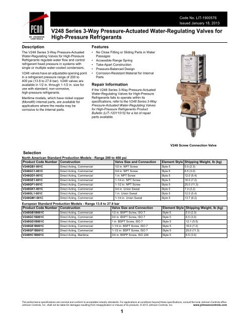
Code No. LIT-1900576Issued January 18, 2013<strong>V248</strong> <strong>Series</strong> 3-<strong>Way</strong> <strong>Pressure</strong>-<strong>Actuated</strong> <strong>Water</strong>-<strong>Regulating</strong> <strong>Valves</strong> <strong>for</strong>High-<strong>Pressure</strong> RefrigerantsDescriptionThe <strong>V248</strong> <strong>Series</strong> 3-<strong>Way</strong> <strong>Pressure</strong>-<strong>Actuated</strong><strong>Water</strong>-<strong>Regulating</strong> <strong>Valves</strong> <strong>for</strong> High-<strong>Pressure</strong>Refrigerants regulate water flow and controlrefrigerant head pressure in systems withsingle or multiple water-cooled condensers.<strong>V248</strong> valves have an adjustable opening pointin a refrigerant pressure range of 200 to400 psi (13.8 to 27.6 bar). <strong>V248</strong> valves areavailable in 1/2 in. through 1-1/2 in. size <strong>for</strong>use with standard, non-corrosive,high-pressure refrigerants.Maritime models, which have nickel copper(Monel®) internal parts, are available <strong>for</strong>applications where the media may becorrosive to the internal parts.Features• No Close Fitting or Sliding Parts in <strong>Water</strong>Passages• Accessible Range Spring• Take-Apart Construction• <strong>Pressure</strong>-Balanced Design• Corrosion-Resistant Material <strong>for</strong> InternalPartsRepair In<strong>for</strong>mationIf the <strong>V248</strong> <strong>Series</strong> 3-<strong>Way</strong> <strong>Pressure</strong>-<strong>Actuated</strong><strong>Water</strong>-<strong>Regulating</strong> <strong>Valves</strong> <strong>for</strong> High-<strong>Pressure</strong>Refrigerants fails to operate within itsspecifications, refer to the <strong>V248</strong> <strong>Series</strong> 3-<strong>Way</strong><strong>Pressure</strong>-<strong>Actuated</strong> <strong>Water</strong>-<strong>Regulating</strong> <strong>Valves</strong><strong>for</strong> High-<strong>Pressure</strong> Refrigerants ProductBulletin (LIT-12011515) <strong>for</strong> a list of repairparts available.<strong>V248</strong> Screw Connection ValveSelectionNorth American Standard Production Models - Range 200 to 400 psiProduct Code Number Construction Valve Size and Connection Element Style Shipping Weight, lb (kg)<strong>V248</strong>GB1-001C Direct Acting, Commercial 1/2 in. NPT Screw Style 5 5.0 (2.3)<strong>V248</strong>GC1-001C Direct Acting, Commercial 3/4 in. NPT Screw Style 5 6.5 (3.0)<strong>V248</strong>GD1-001C Direct Acting, Commercial 1 in. NPT Screw Style 5 12.0 (5.4)<strong>V248</strong>GE1-001C Direct Acting, Commercial 1-1/4 in. NPT Screw Style 5 16.0 (7.2)<strong>V248</strong>GF1-001C Direct Acting, Commercial 1-1/2 in. NPT Screw Style 5 25.0 (11.3)<strong>V248</strong>GK1-001C Direct Acting, Commercial 3/4 in. Union Sweat Style 5 7.0 (3.2)<strong>V248</strong>GL1-001C Direct Acting, Commercial 1 in. Union Sweat Style 5 12.0 (5.4)<strong>V248</strong>GM1-001C Direct Acting, Commercial 1-1/4 in. Union Sweat Style 5 13.7 (6.2)European Standard Production Models - Range 13.8 to 27.8 barProduct Code Number Construction Valve Size and Connection Element Style Shipping Weight, lb (kg)<strong>V248</strong>GB1B001C Direct Acting, Commercial 1/2 in. BSPT Screw, ISO 7 Style 5 5.0 (2.3)<strong>V248</strong>GC1B001C Direct Acting, Commercial 3/4 in. BSPT Screw, ISO 7 Style 5 6.5 (3.0)<strong>V248</strong>GD1B001C Direct Acting, Commercial 1 in. BSPT Screw, ISO 7 Style 5 12.1 (5.5)<strong>V248</strong>GE1B001C Direct Acting, Commercial 1-1/4 in. BSPT Screw, ISO 7 Style 5 16.0 (7.2)<strong>V248</strong>GF1B001C Direct Acting, Commercial 1-1/2 in. BSPT Screw, ISO 7 Style 5 25.0 (11.3)<strong>V248</strong>HC1B001C Direct Acting, Maritime 3/4 in. BSPP Screw, ISO 228 Style 5 6.5 (3.0)The per<strong>for</strong>mance specifications are nominal and con<strong>for</strong>m to acceptable industry standards. For applications at conditions beyond these specifications, consult the local Johnson Controls office.Johnson Controls, Inc. shall not be liable <strong>for</strong> damages resulting from misapplication or misuse of its products. © 2013 Johnson Controls, Inc.www.johnsoncontrols.com1
<strong>V248</strong> <strong>Series</strong> 3-<strong>Way</strong> <strong>Pressure</strong>-<strong>Actuated</strong> <strong>Water</strong>-<strong>Regulating</strong> <strong>Valves</strong> <strong>for</strong> High-<strong>Pressure</strong> Refrigerants (Continued)ApplicationsEach application is unique and requires specific engineering data toproperly size and design a system to fulfill the appropriaterequirements. Typically, a valve is replaced with another valve of thesame size in a properly sized and engineered system. In NorthAmerica, contact Johnson Controls/PENN® Refrigeration ApplicationEngineering at 1-800-275-5676 to obtain specific engineering data. Inother areas, contact the local Johnson Controls® sales office to obtainspecific engineering data.To make a rough field estimate of the size of valve <strong>for</strong> an application,find the valve size needed by locating a point on a flow chart thatsatisfies these requirements:• water flow required by the condenser (Flow)• refrigerant head pressure rise (P RISE )• available water pressure (P AVAIL )Follow these steps, and use the in<strong>for</strong>mation obtained to locate a pointon one of the flowcharts that satisfies all three steps.1. Take the water flow required by the condenser (Flow) fromin<strong>for</strong>mation provided by the manufacturer of the condensing unit. Ifthe manufacturer’s in<strong>for</strong>mation is unavailable, use the followingin<strong>for</strong>mation to make a rough approximation of water flow in gallonsper minute (gpm) [cubic meters per hour (m 3 /hr)]:• System Capacity (Tons of Refrigeration)• Outlet <strong>Water</strong> Temperature (Temp. Outlet )• Inlet <strong>Water</strong> Temperature (Temp. Inlet )Calculate the flow using the following <strong>for</strong>mula:Flow =Tons of Refrigeration x 30(Temp. Outlet - Temp. Inlet)Flow RequiredNote: If the outlet temperature is unknown, assume it to be 10F°(6C°) above the inlet temperature.2. Determine refrigerant head pressure rise above the valve openingpoint (P RISE ) using the following steps:a. The Valve Closing <strong>Pressure</strong> (P CLOSE ) is equal to therefrigerant pressure at the highest ambient temperature therefrigeration equipment experiences in the Off cycle. Use a<strong>Pressure</strong>-Temperature Chart <strong>for</strong> the refrigerant selected to findthis pressure.b. To approximate the Valve Opening <strong>Pressure</strong> (P OPEN ), addabout 10 psi (0.7 bar) to the Valve Closing <strong>Pressure</strong>.P OPEN = P CLOSE +10 psi (0.7 bar)FIG:flw_eqnFIG:eqn_opn_prssrP = P - PRISE COND OPENRefrigerant Head <strong>Pressure</strong> Rise3. Determine the available water pressure to the valve (P AVAIL ) usingthe following steps. This the actual water pressure available to <strong>for</strong>cewater through the valve.a. Determine the minimum inlet pressure (P IN ). This is the waterpressure from city water mains, pumps, or other sources.b. <strong>Pressure</strong> drop through condenser (ΔP COND ) is the difference inwater pressure between the condenser inlet and the condenseroutlet. Obtain this in<strong>for</strong>mation from the condenser manufacturer.c. Estimate or calculate the pressure drop through all associatedpiping (P LOSS ).d. Subtract the ΔP COND and P LOSS from P IN . The result is P AVAIL .PLoss 2P 2P = P -COND 1P 2Cooling TowerCondenserBalancing ValvePAvailable <strong>Water</strong> <strong>Pressure</strong>Pump4. Select the proper valve size from the flowcharts by locating a pointon a chart that satisfies the flow, the head pressure rise aboveopening point, and the pressure drop across the valve.Metric ConversionsUse these equations to convert between U.S. and S.I. units.• 1 dm 3 /s = 3.6 m 3 /h = 15.9 U.S. gal. /min. = 13.2 U.K. gal. /min.• 1 bar = 100 kPa = 0.1 MPa = 1.02 kg/cm 2 = 0.987 atm = 14.5 psiP 13-<strong>Way</strong>ValveFIG:eqn_hd_prssr_rsP Loss 1Bypass LineP P Loss 1 Loss 2FIG:3wy_prss_drpP IN= + + ...LOSSPAVAIL= PIN - ( PCOND+ PLOSS)Valve Opening <strong>Pressure</strong>c. From the <strong>Pressure</strong>-Temperature Chart <strong>for</strong> the refrigerantselected, read the Refrigerant Condensing <strong>Pressure</strong> (P COND )(operating head pressure) corresponding to the selectedcondensing temperature.d. Subtract the Valve Opening <strong>Pressure</strong> from the RefrigerantCondensing <strong>Pressure</strong>. This gives the head pressure rise.The per<strong>for</strong>mance specifications are nominal and con<strong>for</strong>m to acceptable industry standards. For applications at conditions beyond these specifications, consult the local Johnson Controls office.Johnson Controls, Inc. shall not be liable <strong>for</strong> damages resulting from misapplication or misuse of its products. © 2013 Johnson Controls, Inc.www.johnsoncontrols.com2
<strong>V248</strong> <strong>Series</strong> 3-<strong>Way</strong> <strong>Pressure</strong>-<strong>Actuated</strong> <strong>Water</strong>-<strong>Regulating</strong> <strong>Valves</strong> <strong>for</strong> High-<strong>Pressure</strong> Refrigerants (Continued)<strong>V248</strong> FlowchartsThe maximum recommended differential water pressure across a valve is 20 psi (1.4 bar).Flow(gpm)181512Refrigerant Head <strong>Pressure</strong> Above Opening P Rise (bar)0.7 1.4 2.1 2.8 3.5 4.1 4.8 5.5 6.2 6.9<strong>Pressure</strong> Drop20 (1.4)Through Valve,psig (bar) 14.5 (1.0)10 (0.7)4.13.42.7Flow(m³/hr)9635 (0.3)2 (0.1)2.01.40.700.010 20 30 40 50 60 70 80 90 100 110Refrigerant Head <strong>Pressure</strong> Above Opening P Rise ( psig )FIG:<strong>V248</strong>_0.5 in. graph1/2 in. Direct Acting Valve FlowchartRefrigerant Head <strong>Pressure</strong> Above Opening P Rise (bar)0.7 1.4 2.1 2.8 3.5 4.1 4.8 5.5 6.2 6.9Flow25(gpm)20 (1.4)<strong>Pressure</strong> Drop20 Through Valve,14.5 (1.0)psig (bar)10 (0.7)155.74.53.4Flow(M³/hr)1055 (0.3)2 (0.1)2.31.100.010 20 30 40 50 60 70 80 90 100 110Refrigerant Head <strong>Pressure</strong> Above Opening P Rise ( psig )FIG:<strong>V248</strong>_0.75 in. graph3/4 in. Direct Acting Valve FlowchartThe per<strong>for</strong>mance specifications are nominal and con<strong>for</strong>m to acceptable industry standards. For applications at conditions beyond these specifications, consult the local Johnson Controls office.Johnson Controls, Inc. shall not be liable <strong>for</strong> damages resulting from misapplication or misuse of its products. © 2013 Johnson Controls, Inc.www.johnsoncontrols.com3
<strong>V248</strong> <strong>Series</strong> 3-<strong>Way</strong> <strong>Pressure</strong>-<strong>Actuated</strong> <strong>Water</strong>-<strong>Regulating</strong> <strong>Valves</strong> <strong>for</strong> High-<strong>Pressure</strong> Refrigerants (Continued)Refrigerant Head <strong>Pressure</strong> Above Opening P Rise (bar)Flow(gpm)0.7 1.4 2.1 2.8 3.5 4.1 4.8 5.5 6.2 6.950<strong>Pressure</strong> Drop20 (1.4)40 Through Valve,psig (bar)14.5 (1.0)3010 (0.7)11.49.16.8Flow(m³/hr)20105 (0.3)2 (0.1)4.52.300.010 20 30 40 50 60 70 80 90 100 110Refrigerant Head <strong>Pressure</strong> Above Opening P Rise ( psig )1 in. Direct Acting Valve FlowchartFIG:<strong>V248</strong>_1.0 in. graphRefrigerant Head <strong>Pressure</strong> Above Opening P Rise (bar)0.7 1.4 2.1 2.8 3.5 4.1 4.8 5.5 6.2 6.9Flow70(gpm)<strong>Pressure</strong> Drop20 (1.4)60 Through Valve,psig (bar)14.5 (1.0)5010 (0.7)405 (0.3)30202 (0.1)15.913.611.49.16.84.5Flow(m³/hr)102.300.010 20 30 40 50 60 70 80 90 100 110Refrigerant Head <strong>Pressure</strong> Above Opening P Rise ( psig )1-1/4 in. Direct Acting Valve FlowchartFIG:<strong>V248</strong>_1.25 in. graphFlow(gpm)Refrigerant Head <strong>Pressure</strong> Above Opening P Rise (bar)0.7 1.4 2.1 2.8 3.5 4.1 4.8 5.5 6.2 6.980<strong>Pressure</strong> Drop70 Through Valve,20 (1.4)psig (bar)6014.5 (1.0)5040302010010 20 30 40 50 60 70 80 90 100 110Refrigerant Head <strong>Pressure</strong> Above Opening P Rise ( psig )10 (0.7)5 (0.3)2 (0.1)18.215.913.611.49.16.84.52.30.0Flow(m³/hr)FIG:<strong>V248</strong>_1.5 in. graph1-1/2 in. Direct Acting Valve FlowchartThe per<strong>for</strong>mance specifications are nominal and con<strong>for</strong>m to acceptable industry standards. For applications at conditions beyond these specifications, consult the local Johnson Controls office.Johnson Controls, Inc. shall not be liable <strong>for</strong> damages resulting from misapplication or misuse of its products. © 2013 Johnson Controls, Inc.www.johnsoncontrols.com4
<strong>V248</strong> <strong>Series</strong> 3-<strong>Way</strong> <strong>Pressure</strong>-<strong>Actuated</strong> <strong>Water</strong>-<strong>Regulating</strong> <strong>Valves</strong> <strong>for</strong> High-<strong>Pressure</strong> Refrigerants (Continued)ABABPort 1 Port 2CDPort 1Port 2CDEEPort 3PluggedFPort 3PluggedF<strong>V248</strong> 1/2 in. Through 1-1/4 in. Screw Connection <strong>Valves</strong>DimensionsFIG:<strong>V248</strong>_thdd<strong>V248</strong> Union Sweat Connection <strong>Valves</strong> DimensionsFIG:<strong>V248</strong>_unbdyEPORT 3PORT 1PORT 2FIG:<strong>V248</strong>_3 way valve<strong>V248</strong> 1-1/2 in. Screw Connection <strong>Valves</strong> DimensionsThe per<strong>for</strong>mance specifications are nominal and con<strong>for</strong>m to acceptable industry standards. For applications at conditions beyond these specifications, consult the local Johnson Controls office.Johnson Controls, Inc. shall not be liable <strong>for</strong> damages resulting from misapplication or misuse of its products. © 2013 Johnson Controls, Inc.www.johnsoncontrols.com5
<strong>V248</strong> <strong>Series</strong> 3-<strong>Way</strong> <strong>Pressure</strong>-<strong>Actuated</strong> <strong>Water</strong>-<strong>Regulating</strong> <strong>Valves</strong> <strong>for</strong> High-<strong>Pressure</strong> Refrigerants (Continued)<strong>V248</strong> 1/2 in. Through 1-1/4 in. Screw Connection <strong>Valves</strong> DimensionsValve SizeDimensions in Inches (Millimeters)A B C D E F1/2 in. 3-1/16 (78) 2 (51) 8-11/16 (220) 3-13/16 (96) 1-1/2 (38) 3-3/8 (86)3/4 in. 3-3/8 (86) 2-3/16 (55) 9-3/4 (248) 4-3/16 (106) 1-3/4 (44) 3-13/16 (98)1 in. 4-3/4 (121) 2-13/16 (71) 12-1/2 (318) 5-15/16 (151) 2-1/16 (52) 4-1/2 (114)1-1/4 in. 4-3/4 (121) 2-13/16 (71) 13-1/4 (336) 6-1/8 (156) 2-3/8 (60) 4-3/4 (121)<strong>V248</strong> Union Sweat Connection <strong>Valves</strong> DimensionsValve SizeDimensions in Inches (Millimeters)A B C D E F3/4 in. 3-3/8 (86) 2-3/16 (55) 9-3/4 (248) 4-3/16 (106) 1-3/4 (44) 3-13/16 (98)1 in. 4-3/4 (121) 2-13/16 (71) 12-1/2 (318) 5-15/16 (151) 2-1/16 (52) 4-1/2 (114)1-1/4 in. 4-3/4 (121) 2-13/16 (71) 13-1/4 (336) 6-1/8 (156) 2-3/8 (60) 4-3/4 (121)<strong>V248</strong> 1-1/2 in. Screw Connection <strong>Valves</strong> DimensionsValve SizeDimensions in Inches (Millimeters)A B C D E F1-1/2 in. 6 (152) 3-1/2 (89) 15-1/4 (382) 8 (203) 9-5/16 (237) 6-7/8 (175)The per<strong>for</strong>mance specifications are nominal and con<strong>for</strong>m to acceptable industry standards. For applications at conditions beyond these specifications, consult the local Johnson Controls office.Johnson Controls, Inc. shall not be liable <strong>for</strong> damages resulting from misapplication or misuse of its products. © 2013 Johnson Controls, Inc.www.johnsoncontrols.com6
Materials<strong>V248</strong> <strong>Series</strong> 3-<strong>Way</strong> <strong>Pressure</strong>-<strong>Actuated</strong> <strong>Water</strong>-<strong>Regulating</strong> <strong>Valves</strong> <strong>for</strong> High-<strong>Pressure</strong> Refrigerants (Continued)North American <strong>V248</strong> MaterialsNominal Valve Size:3/8 in. to 3/4 in.1 in. to 1-1/2 in.Maritime (All Sizes)MaterialBody(Commercial)Cast Brass(Commercial)Cast Iron/Rust Resisting Finish Cast BronzeSeat Aluminum Bronze Aluminum Bronze MonelDisc BUNA-N BUNA-N BUNA-NDisc Cup Brass Brass MonelDisc Stud Brass Brass MonelStem/Extension Sleeve Brass Brass MonelDiaphragms Nylon Rein<strong>for</strong>ced BUNA-N Nylon Rein<strong>for</strong>ced BUNA-N Nylon Rein<strong>for</strong>ced BUNA-NRefrigerant Contact<strong>Pressure</strong> Cup 300 <strong>Series</strong> Stainless Steel 300 <strong>Series</strong> Stainless Steel 300 <strong>Series</strong> Stainless SteelElementBellows 300 <strong>Series</strong> Stainless Steel 300 <strong>Series</strong> Stainless Steel 300 <strong>Series</strong> Stainless SteelBellows Ring Steel/Nickel Plated Steel/Nickel Plated Steel/Nickel PlatedEuropean <strong>V248</strong> MaterialsNominal Valve Size:3/8 in. to 3/4 in.1 in. to 1-1/2 in.Maritime (All Sizes)MaterialBody(Commercial)Hot Forged Brass(Commercial)Cast Iron/Rust Resisting Finish Cast BronzeSeat Aluminum Bronze Aluminum Bronze MonelDisc BUNA-N BUNA-N BUNA-NDisc Cup Brass Brass MonelDisc Stud Brass Brass MonelStem/Extension Sleeve Brass Brass MonelDiaphragms Nylon Rein<strong>for</strong>ced BUNA-N Nylon Rein<strong>for</strong>ced BUNA-N Nylon Rein<strong>for</strong>ced BUNA-NRefrigerant Contact<strong>Pressure</strong> Cup 300 <strong>Series</strong> Stainless Steel 300 <strong>Series</strong> Stainless Steel 300 <strong>Series</strong> Stainless SteelElementBellows 300 <strong>Series</strong> Stainless Steel 300 <strong>Series</strong> Stainless Steel 300 <strong>Series</strong> Stainless SteelBellows Ring Steel/Nickel Plated Steel/Nickel Plated Steel/Nickel PlatedTechnical SpecificationsProduct<strong>V248</strong> <strong>Series</strong> <strong>Pressure</strong>-<strong>Actuated</strong> <strong>Water</strong>-<strong>Regulating</strong> <strong>Valves</strong> <strong>for</strong> High-<strong>Pressure</strong> RefrigerantsMaximum Working <strong>Pressure</strong> 630 psi (43.4 bar)Factory-Set Opening Point (Port 1 to 275 psi (19.0 bar)Port 2)Opening Point Adjustment Range 200 to 400 psi (13.8 to 27.6 bar)(Port 1 to Port 2)Throttling Range120 psi (8.3 bar) <strong>for</strong> 1/2 in. size100 psi (6.9 bar) <strong>for</strong> 3/4 in., 1 in., and 1-1/4 in. sizes140 psi (9.6 bar) <strong>for</strong> 1-1/2 in. sizeMedia150 psi (10.3 bar) Maximum,-4°F to 170°F (-20°C to 77°C) glycol/water or liquids with low freezing points that are compatible with valve materialsThe per<strong>for</strong>mance specifications are nominal and con<strong>for</strong>m to acceptable industry standards. For applications at conditions beyond these specifications, consult the local Johnson Controls office.Johnson Controls, Inc. shall not be liable <strong>for</strong> damages resulting from misapplication or misuse of its products. © 2013 Johnson Controls, Inc.www.johnsoncontrols.com7


